EP1098102A2 - Connecting device for control cable - Google Patents
Connecting device for control cable Download PDFInfo
- Publication number
- EP1098102A2 EP1098102A2 EP00309690A EP00309690A EP1098102A2 EP 1098102 A2 EP1098102 A2 EP 1098102A2 EP 00309690 A EP00309690 A EP 00309690A EP 00309690 A EP00309690 A EP 00309690A EP 1098102 A2 EP1098102 A2 EP 1098102A2
- Authority
- EP
- European Patent Office
- Prior art keywords
- lever
- control cable
- end fitting
- strut
- cable
- Prior art date
- Legal status (The legal status is an assumption and is not a legal conclusion. Google has not performed a legal analysis and makes no representation as to the accuracy of the status listed.)
- Withdrawn
Links
Images



Classifications
-
- F—MECHANICAL ENGINEERING; LIGHTING; HEATING; WEAPONS; BLASTING
- F16—ENGINEERING ELEMENTS AND UNITS; GENERAL MEASURES FOR PRODUCING AND MAINTAINING EFFECTIVE FUNCTIONING OF MACHINES OR INSTALLATIONS; THERMAL INSULATION IN GENERAL
- F16C—SHAFTS; FLEXIBLE SHAFTS; ELEMENTS OR CRANKSHAFT MECHANISMS; ROTARY BODIES OTHER THAN GEARING ELEMENTS; BEARINGS
- F16C1/00—Flexible shafts; Mechanical means for transmitting movement in a flexible sheathing
- F16C1/10—Means for transmitting linear movement in a flexible sheathing, e.g. "Bowden-mechanisms"
- F16C1/12—Arrangements for transmitting movement to or from the flexible member
- F16C1/14—Construction of the end-piece of the flexible member; Attachment thereof to the flexible member
-
- F—MECHANICAL ENGINEERING; LIGHTING; HEATING; WEAPONS; BLASTING
- F16—ENGINEERING ELEMENTS AND UNITS; GENERAL MEASURES FOR PRODUCING AND MAINTAINING EFFECTIVE FUNCTIONING OF MACHINES OR INSTALLATIONS; THERMAL INSULATION IN GENERAL
- F16C—SHAFTS; FLEXIBLE SHAFTS; ELEMENTS OR CRANKSHAFT MECHANISMS; ROTARY BODIES OTHER THAN GEARING ELEMENTS; BEARINGS
- F16C1/00—Flexible shafts; Mechanical means for transmitting movement in a flexible sheathing
- F16C1/10—Means for transmitting linear movement in a flexible sheathing, e.g. "Bowden-mechanisms"
- F16C1/12—Arrangements for transmitting movement to or from the flexible member
-
- F—MECHANICAL ENGINEERING; LIGHTING; HEATING; WEAPONS; BLASTING
- F16—ENGINEERING ELEMENTS AND UNITS; GENERAL MEASURES FOR PRODUCING AND MAINTAINING EFFECTIVE FUNCTIONING OF MACHINES OR INSTALLATIONS; THERMAL INSULATION IN GENERAL
- F16D—COUPLINGS FOR TRANSMITTING ROTATION; CLUTCHES; BRAKES
- F16D65/00—Parts or details
- F16D65/14—Actuating mechanisms for brakes; Means for initiating operation at a predetermined position
- F16D65/16—Actuating mechanisms for brakes; Means for initiating operation at a predetermined position arranged in or on the brake
- F16D65/22—Actuating mechanisms for brakes; Means for initiating operation at a predetermined position arranged in or on the brake adapted for pressing members apart, e.g. for drum brakes
-
- F—MECHANICAL ENGINEERING; LIGHTING; HEATING; WEAPONS; BLASTING
- F16—ENGINEERING ELEMENTS AND UNITS; GENERAL MEASURES FOR PRODUCING AND MAINTAINING EFFECTIVE FUNCTIONING OF MACHINES OR INSTALLATIONS; THERMAL INSULATION IN GENERAL
- F16C—SHAFTS; FLEXIBLE SHAFTS; ELEMENTS OR CRANKSHAFT MECHANISMS; ROTARY BODIES OTHER THAN GEARING ELEMENTS; BEARINGS
- F16C2361/00—Apparatus or articles in engineering in general
- F16C2361/45—Brakes
-
- F—MECHANICAL ENGINEERING; LIGHTING; HEATING; WEAPONS; BLASTING
- F16—ENGINEERING ELEMENTS AND UNITS; GENERAL MEASURES FOR PRODUCING AND MAINTAINING EFFECTIVE FUNCTIONING OF MACHINES OR INSTALLATIONS; THERMAL INSULATION IN GENERAL
- F16D—COUPLINGS FOR TRANSMITTING ROTATION; CLUTCHES; BRAKES
- F16D2125/00—Components of actuators
- F16D2125/18—Mechanical mechanisms
- F16D2125/58—Mechanical mechanisms transmitting linear movement
- F16D2125/60—Cables or chains, e.g. Bowden cables
-
- F—MECHANICAL ENGINEERING; LIGHTING; HEATING; WEAPONS; BLASTING
- F16—ENGINEERING ELEMENTS AND UNITS; GENERAL MEASURES FOR PRODUCING AND MAINTAINING EFFECTIVE FUNCTIONING OF MACHINES OR INSTALLATIONS; THERMAL INSULATION IN GENERAL
- F16D—COUPLINGS FOR TRANSMITTING ROTATION; CLUTCHES; BRAKES
- F16D2125/00—Components of actuators
- F16D2125/18—Mechanical mechanisms
- F16D2125/58—Mechanical mechanisms transmitting linear movement
- F16D2125/60—Cables or chains, e.g. Bowden cables
- F16D2125/62—Fixing arrangements therefor, e.g. cable end attachments
-
- F—MECHANICAL ENGINEERING; LIGHTING; HEATING; WEAPONS; BLASTING
- F16—ENGINEERING ELEMENTS AND UNITS; GENERAL MEASURES FOR PRODUCING AND MAINTAINING EFFECTIVE FUNCTIONING OF MACHINES OR INSTALLATIONS; THERMAL INSULATION IN GENERAL
- F16D—COUPLINGS FOR TRANSMITTING ROTATION; CLUTCHES; BRAKES
- F16D2125/00—Components of actuators
- F16D2125/18—Mechanical mechanisms
- F16D2125/58—Mechanical mechanisms transmitting linear movement
- F16D2125/68—Lever-link mechanisms, e.g. toggles with change of force ratio
-
- Y—GENERAL TAGGING OF NEW TECHNOLOGICAL DEVELOPMENTS; GENERAL TAGGING OF CROSS-SECTIONAL TECHNOLOGIES SPANNING OVER SEVERAL SECTIONS OF THE IPC; TECHNICAL SUBJECTS COVERED BY FORMER USPC CROSS-REFERENCE ART COLLECTIONS [XRACs] AND DIGESTS
- Y10—TECHNICAL SUBJECTS COVERED BY FORMER USPC
- Y10T—TECHNICAL SUBJECTS COVERED BY FORMER US CLASSIFICATION
- Y10T74/00—Machine element or mechanism
- Y10T74/20—Control lever and linkage systems
- Y10T74/20396—Hand operated
- Y10T74/20402—Flexible transmitter [e.g., Bowden cable]
- Y10T74/2045—Flexible transmitter [e.g., Bowden cable] and sheath support, connector, or anchor
-
- Y—GENERAL TAGGING OF NEW TECHNOLOGICAL DEVELOPMENTS; GENERAL TAGGING OF CROSS-SECTIONAL TECHNOLOGIES SPANNING OVER SEVERAL SECTIONS OF THE IPC; TECHNICAL SUBJECTS COVERED BY FORMER USPC CROSS-REFERENCE ART COLLECTIONS [XRACs] AND DIGESTS
- Y10—TECHNICAL SUBJECTS COVERED BY FORMER USPC
- Y10T—TECHNICAL SUBJECTS COVERED BY FORMER US CLASSIFICATION
- Y10T74/00—Machine element or mechanism
- Y10T74/20—Control lever and linkage systems
- Y10T74/20396—Hand operated
- Y10T74/20402—Flexible transmitter [e.g., Bowden cable]
- Y10T74/20462—Specific cable connector or guide
Definitions
- the present invention relates to a device for operating a pair of members to be operated, such as brake shoes in a drum brake, so as to mechanically move these members away from each other through the manipulation of a lever, and in more detail, a device for detachably connecting a control cable to the lever.
- a control cable connecting device for the above-mentioned operating device there has conventionally been known, for example, a device as shown in Figs. 10a and 10b for detachably connecting a brake cable with a lever for operating a drum brake, which is disclosed in U. S. Patent specification No. 5,311,793.
- a pair of brake shoes 1, 2 as members to be operated, a bracket 3, a lever 4, and a brake cable 5 as a control cable, which interact with one another as explained as follows, so as to constitute an operating device 6 for a drum brake.
- the bracket 3 is formed at its one end with a cut-out 3a to which one of the brake shoes 1 is engaged, and the bracket 3 is provided at the other end with the lever 4 pivotally journalled at its proximal end by means of a pivot pin 7, while the lever 4 is formed at the proximal end with cut-outs 4a to which the other brake shoe 2 is engaged.
- the lever 4 is further formed at its free end with cut-outs 4b to which an end fitting 5a of the brake cable 5 is engaged in a cable pulling direction.
- the brake shoes 1, 2 are moved away from each other and are pressed against the inner peripheral surface of a brake drum which is not shown, whereby a braking operation can be carried out.
- the operating device 6 for a drum brake is preferably constituted in such manner that the brake cable 5 can be engaged with or disengaged from the cut-outs 4b of the lever 4 while the drum brake is incorporated in useable condition, and accordingly, the operating device 6 is further incorporated therein additionally with the following arrangement.
- the bracket 3 is forked, except the end part where the cut-out 3a is formed, so as to have a space which is defined by a pair of opposed legs 3b, 3c and an inner end wall 3d, in which space the lever 4 is accommodated.
- lever 4 is also forked, except the proximal end in which the pivot pin 7 and the cut-outs 4a are provided, so as to define a space between a pair of opposed legs 4c, 4d, though which space the brake cable 5 can pass.
- the distance between the pair of opposed legs 4c, 4d is selected such that the end fitting 5a of the brake cable 5 cannot pass through the space and the opposed legs 4c, 4d are formed respectively with the above-mentioned cut-outs 4b for engaging the end fitting 5a.
- the distance "A" as a gap between the free end face of the lever 4 and the inner end wall 3d of the bracket 3 is set to be such a size that the end fitting 5a can pass through, and a V-shaped leaf spring 8 is interposed so as to block the above gap, one leg 8a of the leaf spring 8 is made into close contact with the inner end wall 3d.
- the other leg 8b of the leaf spring 8 is made into close contact with the free end face of the lever 4 to define a convergent tapering space 9 between the other leg 8b and the free end face of the lever 4, which convergent tapering space 9 guides the end fitting 5a upon insertion of the latter which will be explained hereinafter.
- the end fitting 5a further advances while elastically deforming the spring leg 8b in a direction indicated by the arrow ⁇ with using the free end face of the lever 4 as a reaction force receiver.
- the end fitting 5a overrides the free end face of the lever 4, the end fitting 5a is pushed by elastic restoration of the spring leg 8b in a reverse direction against which indicated by the arrow ⁇ so that the end fitting 5a is engaged with the cut-outs 4b.
- the spring leg 8b Upon detaching the brake cable 5, the spring leg 8b is elastically deformed in the direction indicated by the arrow ⁇ with use of a suitable tool inserted from the outside of the drum brake, and in this condition, in reverse order of the aforementioned steps, the end fitting 5a is disengaged from the cut-outs 4b, and then the brake cable 5 is pulled out so as to be removed.
- the gap required for passing the end fitting 5a as indicated by "A" in Fig. 10b should be set to a value which is larger than the sum of the diameter of the end fitting 5a and the value twice as large as the thickness of the V-shaped leaf spring 8.
- An aim of a first aspect of the present invention is to provide a device for connecting a control cable, in which an end fitting of the control cable can be inserted into a position between the journalled portion and the free end of the lever so as to be engaged with or disengaged from the free end of the lever, whereby eliminating or alleviating the above-mentioned problems inherent to conventional operating devices, that is, the problems such that the overall length of the operating device become longer and the brake operating force becomes larger due to the lever ratio of the lever to be ensured, and whereby satisfying both requirements of shortening the overall length of the operating device and of reducing the brake operating force.
- a device for connecting a control cable for use in an operating device comprising
- the overall length of the operating device can be shortened by a degree corresponding to a decrease of the insertion gap, while the lever ratio of the lever can be increased to reduce the operating force, thereby satisfying both requirements of shortening of the overall length of the operating device and of reducing the operating force of the operating device.
- An aim of a second aspect of the present invention is to provide a device for connecting a control cable, which is arranged to inexpensively achieve the functional effects and advantages exhibited by the first aspect of the present invention.
- a device for connecting a control cable characterized in that the lever is composed of a pair of planar members opposed to each other, which planar members are coupled with each other at a portion corresponding to the proximal end of the lever to be pivotally journalled to the other end of the strut, and which planar members are spaced from each other at a portion corresponding to the free end of the lever so as to define a narrow gap between the planar members, having a size which allow a cable itself of the control cable to pass therethrough but which inhibits the end fitting of the control cable from passing therethrough, and to define a wide gap between the planar members at a longitudinally middle portion so as to step down to the narrow gap, having a size which allow the end fitting of the control cable to pass therethrough.
- An aim of a third aspect of the present invention is to provide a device for connecting a control cable, which can enhance the workability upon insertion of the end fitting of the control cable during attaching operation of the control cable.
- a device for connecting a control cable characterized in that the end fitting of the control cable has a shape in which one side is longer than the other side as viewed in the longitudinal direction of the control cable, and the wide gap has a size with which the length of the one side of the end fitting can pass through the wide gap.
- An aim of a fourth aspect of the present invention is to provide a device for connecting a control cable, which can reduce the widthwise dimension of the operating device.
- a device for connecting a control cable characterized in that the end fitting of the control cable has a shape in which one side is longer than the other side as viewed in the longitudinal direction of the control cable, and the wide gap has a size with which the length of the other side of the end fitting can pass therethrough, but the length of the one side cannot pass therethrough.
- the overall width of the operating device can be reduced by a degree corresponding to a decrease in width of the wide gap.
- An aim of a fifth aspect of the present invention is to provide a device for connecting a control cable, in which the end fitting of the control cable can be inserted even though the lever is not held, and accordingly, the control cable can be attached after the operating device is attached in useable condition, thereby it is possible to facilitate the handling and the conveyance of the assembly to which the operating device is attached.
- a device for connecting a control cable characterized in that the lever is provided with an end fitting stopper for receiving the end fitting of the control cable upon insertion thereof so as to determine an insertion position thereof, and the strut is provided with a lever abutting part for restricting the rotation of the lever relative to the strut in the direction of insertion of the end fitting.
- the end fitting does not interfere with any other component when the end fitting has been inserted into the wide gap, and a worker can sense such a fact that the insertion work of the end fitting has been completed, thereby it is possible to facilitate the engagement or disengagement of the end fitting of the control cable.
- the end fitting can be inserted into the lever even though the lever is not held, and accordingly, the control cable can be connected to the operating device which has been attached in useable condition. Thereby it is possible to facilitate the handling and the conveyance of a unit such as a drum brake or the like in which the operating device is incorporated.
- An aim of a sixth aspect of the present invention is to provide a device for connecting a control cable, which allows a worker to sense the completion of insertion work of the end fitting.
- a device for connecting a control cable characterized in that the strut is provided with an end fitting stopper for receiving the end fitting of the control cable upon insertion thereof so as to determine an insertion position thereof.
- the end fitting does not interfere with any other component upon insertion thereof into the wide gap, and a worker can senses completion of the insertion work of the end fitting, thereby it is possible to facilitate the engagement or disengagement of the end fitting of the control cable.
- An aim of a seventh aspect of the present invention is to provide a device for connecting a control cable which can exhibit functional effects and advantages similar to those exhibited by the fifth aspect of the present invention with use of another means which is different from the fifth aspect of the present invention.
- a device for connecting a control cable characterized in that there is provided on the strut the lever abutting part for restricting the rotation of the lever relative to the strut in the direction of insertion of the end fitting of the control cable.
- the end fitting can be inserted even though the lever is not held, and accordingly, the control cable can be connected to the operating device which has been attached in useable condition. It is possible to achieve, with use of another means different from the fifth aspect of the present invention, the functional effects similar to those attained, thereby such that the handling and the conveyance of a unit such as a drum brake which is attached with the operating device can be facilitated.
- An aim of an eighth aspect of the present invention is to provide a device for connecting a control cable which can simply and inexpensively achieve the functional effects of the sixth and the seventh aspects of the present invention by structure which can be formed with use of press work.
- a device for connecting a control cable characterized in that the strut is composed of opposed side walls between which the lever is interposed on opposite sides in the direction of the rotational axis of the lever, and a bridge part connecting between the opposed side walls which bridge part serves as the end fitting stopper, the lever abutting parts or both of them.
- An aim of a ninth aspect of the present invention is to provide a device for connecting a control cable, which can simply and inexpensively achieve functional effects obtained by both seventh and eighth aspects of the present invention by structure which can be formed with use of press work.
- a device for connecting a control cable characterized in that the strut is provided with two bridge parts one of which is arranged in opposition to an intermediate part between the journalled portion and the free end of the lever so as to serve as the end fitting stopper, and the other one of which is located in the vicinity of the journalled portion of the lever so as to serve as the lever abutting part.
- An aim of a tenth aspect of the present invention is to provide a device for connecting a control cable, which can prevent the end fitting of the control cable from interfering with another component when the end fitting is engaged with the free end of the lever after insertion.
- a device for connecting a control cable characterized in that the bridge part serving as the end fitting stopper is provided with an end fitting guide piece extended toward the narrow gap.
- the end fitting of the control cable does not interfere with any other component when the end fitting is engaged with the free end of the lever after insertion, thereby it is possible to enhance the workability for connecting the control cable,
- An aim of an eleventh aspect of the present invention is to provide a device for connecting a control cable, which can prevent the end fitting of the control cable from interfering with any other component even if the control cable is slackened after the end fitting has been engaged with the free end of the lever.
- a device for connecting a control cable characterized in that the end fitting guide piece is extended to a position above the narrow gap.
- the end fitting can be prevented from interfering with another component even if the control cable is slackened after the end fitting has been engaged with free end of the lever.
- An aim of a twelfth aspect of the present invention is to provide a device for connecting a control cable, in which the slide motion between the end fitting and the lever becomes smooth in a condition such that the end fitting is engaged with the free end of the lever, so that the durability of the operating device can be enhanced.
- a device for connecting a control cable characterized in that the engagement of the end fitting of the control cable with the free end of the lever is obtained through cylindrical surfaces.
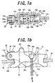
- Figs. 1a and 1b which show a drum brake operating device 10 incorporating a device for connecting a control cable according to a preferred embodiment of the present invention
- the operating device 10 is substantially composed of a strut 11 and a lever 12.
- the strut 11, as shown in Fig. 1b, is arranged between one ends of brake shoes 13, 14 as members to be operated, and the strut 11 is formed at its one end with a brake shoe engaging groove 11a for the one brake shoe 13.
- the lever 12 is pivotally journalled at its proximal end 12a to an other end 11b of the strut 11 by means of a pivot pin 15, and the lever 12 is formed with a brake shoe engaging groove 12b for the other brake shoe 14, which brake shoe engaging groove 12b is arranged in the vicinity of the journalled portion of the lever 12.
- the strut 11 is formed of a single plate which is bent in the form of a rectangular frame.
- This rectangular frame has side walls 11c and 11d opposed to each other, which side walls 11c, 11d are made into close contact with and joined to each other by spot welling or the like, at one ends where the brake shoe engaging groove 11a is formed.
- the lever 12 is composed of a pair of planar members 12c, 12d opposed to each other. These planar members 12c, 12d are made into close contact with and joined to each other by spot welding or the like, at a portion corresponding to the proximal end 12a of the lever 12 to be pivotally journalled to the other end 11b of the strut 11 by the pin 15.
- the planar members 12c, 12d are spaced from each other in a forked shape to form a gap, as shown in Fig. 1a in the remaining portion except the above-mentioned portion, which gap is determined as will be explained latter in relation to the end fitting 16a to be connected to the free end of the lever 12.
- the end fitting 16a has, for example, a columnar shape, having one side of a length L 1 which is longer than the length L 2 of the other side as shown in Fig. 1a, 1b, as viewed in the longitudinal direction of the control cable 16.
- a gap 12f between the planer members 12c, 12d at a position corresponding to the free end 12e of the lever 12 is a relatively narrow gap having a width W 1 through which a cable itself of the control cable 16 can pass but the end fitting 16a of the control cable 16 at least at its long side L 1 cannot pass so that the end fitting 16a can be engaged with the free end 12e in a direction same as the cable pulling direction W.
- planar members 12c, 12d are formed at portions corresponding to the free end 12e of the lever 12, respectively, with end fitting engaging recesses 12g for engaging the columnar shaped end fitting 16a, which end fitting engaging recesses 12g have circular arc shaped engaging surfaces which are curved so as to have a curvature similar to that of the outer periphery of the end fitting 16a.
- the gap 12h between the planar members 12c, 12d at the longitudinally middle position of the lever 12 is a relatively wide gap having a width W 2 through which the long side L 1 of the end fitting 16a can pass, and which wide gap 12h is stepped down to the narrow gap 12f.
- Protrusions 12i disposed on the planar members 12c, 12d also in the longitudinally middle position of the lever 12 are formed on the upper edges of the planar members 12c, 12d on the side remote from the cable pulling direction "W", so as to protrude in direction approaching to each other.
- the distance W 3 between the protrusions 12i is set to be smaller than the long side L 1 of the end fitting 16a, so that the protrusions 12i serve as end fitting stoppers having a function which will be explained later.
- both brake shoes 13, 14 are moved away from each other, and are pressed against the inner peripheral surface of a brake drum which is not shown, so as to carry out a braking operation.
- the end fitting 16a is inserted in the wide gap 12h between the planar members 12c, 12d in a reverse direction against the cable pulling direction "W" so as to abut against the protrusions 12i as shown in the Fig. 2a.
- control cable 16 can be made by carrying out the above-mentioned steps in the reverse order.
- the end fitting 16a When the control cable 16 is connected to the operating device 10, the end fitting 16a is led through the wide gap 12h defined between the planar members 12c, 12d in the longitudinally middle position of the lever 12, and thereafter, the control cable 16 is shifted toward the free end 12e of the lever 12 in order to engage the end fitting 16a with the end fitting engaging recesses 12g, it is not required to set a gap indicated by "A" in Fig. 10b, between the free end face of the lever 12 and the strut 11. Accordingly, the overall length of the operating device 10 can be shortened by a degree corresponding to the decrease of this gap. Further, in such a case that it is not required to shorten the overall length of the operating device 10, the lever ratio of the lever 12 is increased so as to reduce the brake operating force.
- the end fitting 16a upon engagement or disengagement of the end fitting 16a, it can be made only by insertion or removal of the end fitting 16a into or from the drum brake and by shifting the control cable 16 to or from the free end of the lever 12. Accordingly, also due to the fact that the rotation of the control cable 16 by an angle of 90 deg. around its longitudinal axis is not required, the end fitting 16a can be engaged and disengaged in an extremely simple manner.
- the lever 12 is provided with the protrusions 12i against which the end fitting 16a abuts when it is inserted in the wide gap 12h, and that the rotation of the lever 12 caused by the above abutting of the end fitting 16a is adapted to be inhibited by the bridge part 11e of the strut 11, it is possible to prevent the end fitting 16a from interfering with another component during insertion of the end fitting 16a, and to make a worker to sense the completion of the insertion work of the end fitting 16a, in these points the engagement or disengagement of the end fitting 16a can be facilitated.
- the control cable 16 can be connected to the operating device 10 even after the operating device 10 is incorporated in the drum brake, whereby it is possible to facilitate the handling and the conveyance of the drum brake incorporated therein with the operating device 10.
- strut 11 is provided with a bridge part 11f which, in stead of the protrusions 12i provided on the lever 12 shown in Figs. 1a, 1b and 2a, 2b, can restrict the inserted position of the end fitting 16a of the control cable 16.
- the bridge part 11f is not located at a position in the vicinity of the journalled portion (pivot pin 15) between the strut 11 and the lever 12, but is located above the wide gap 12h so as to be used as an end fitting stopper.
- the lever 12 (the planar members 12c, 12d) is provided with protrusions 12j, as shown in Fig. 3b, which are adapted to make contact with the bridge part 11f so as to restrict the rotating position of the lever 12 to the same position as that shown in Figs. 1a, 1b and 2a, 2b.
- the end fitting 16a When the end fitting 16a is inserted from the outside of the drum brake so as to be engaged with the lever 12 (in more detail, the end fitting engaging recesses 12g) in the operating device 10, the end fitting 16a is led through the back plate 17 of the drum brake while its long side having the length L 1 is directed orthogonal to the planar members 12c, 12d of the lever 12.
- the end fitting 16a is inserted in the wide gap 12h between the planar members 12c, 12d in the reverse direction against the cable pulling, and is abutted against the bridge part 11f as shown.
- control cable 16 is shifted toward the free end 12e of the lever 12 so as to engage the end fitting 16a with the end fitting engaging recesses 12g.
- the overall length of the operating device 10 can be shortened, and further, the lever ratio of the lever 12 can be increased so as to reduce the brake operating force, whereby it is able to satisfy both requirements of shortening the overall length of the operating device 10 and of reducing the brake operating force.
- the end fitting 16a abuts against the bridge part 11f when the end fitting 16a is inserted in the wide gap 12h, and in this period the rotation of the lever 12 is inhibited by the bridge part 11f, the end fitting 16a can be prevented from interfering with another component during insertion thereof, and a worker can sense the completion of insertion work of the end fitting 16a. Accordingly, it is also possible to facilitate the engagement or disengagement of the end fitting 16a can be facilitated also in view of these points.
- the control cable 16 can be connected to the operating device 10 even after the operating device 10 is incorporated in the drum brake, and accordingly, the handling and the conveyance of the drum brake incorporating the operating device 10 can be facilitated.
- the bridge part 11f of the strut 11 has both of two functions indispensable to the above advantages, that is, the function of the end fitting stopper for determining the restricted position of the end fitting 16a during insertion of the latter into the wide gap 12h, and the function of the lever abutting part for restricting the rotating position of the lever 12 to the position shown in Fig. 3a, the functional effects and advantages similar to those obtained by the aforementioned embodiment can be more simply and inexpensively achieved.
- the end fitting guide piece 11g is provided integrally on the bridge part 11f extending to a position above the narrow gap 12f.
- This guide piece 11g surely guides the end fitting 16a when the end fitting 16a is shifted toward the end fitting engaging recesses 12g of the lever 12, thereby it is possible to prevent the end fitting 16a from interfering with another component and being the above work free from difficulties.
- the guide piece 11g can also prevent the end fitting 16a from being largely projected from the end fitting engaging recesses 12g even if the control cable 16 has been slackened after the end fitting 16a is engaged with the end fitting engaging recesses 12g, for example, such as before the adjustment work for the pulling margin of the control cable 16 is completed after connection of the control (opposite end) side of the control cable 16, so that even at this time it is possible to prevent the end fitting 16a from interfering with another component.
- a bridge part 11f which is arranged at a position similar to that shown in Figs. 3a, 3b, only serves as the end fitting stopper, the function of the lever abutting part can be obtained by a bridge part 11e which is arranged at a position similar to that shown in Fig. 2.
- Fig. 5a, 5b which shows a further another embodiment of the present invention
- the width W 2 of the wide gap 12h under the bridge part 11f is set to a value which allows the short side L 2 of the end fitting 16a to pass through the wide gap 12h but inhibits the long side L 1 from passing through.
- the end fitting 16a is inserted into the wide gap 12h between the planar plates 12c, 12d in a reverse direction against the cable pulling so as to abut against the bridge part 11f as shown in the figures.
- control cable 16 is rotated around the longitudinal axis thereof by an angle of 90 deg. as shown by the arrow ⁇ in Fig. 5b so that the long side L 1 of the end fitting 16a is directed orthogonal to the planar members 12c, 12d of the lever 12.
- control cable 16 is pulled in the pulling direction "W" so as to engage the end fitting 16a with the end fitting engaging recesses 12g on the free end 12e of the lever 12, as indicated by the two-dot-chain line. It should be noted that the control cable 16 is removed from the operating device 10 by carrying out the above-mentioned steps in the reverse order.
- the functional effects and advantages similar to those which can be exhibited by the aforementioned embodiments, can be achieved, and following another advantage can be also achieved. Namely, in this embodiment, since the width W 2 of the wide gap 12h can be made to be smaller than that in the embodiments shown in Figs. 1a, 1b, 2a, 2b, 3a, 3b, 4a, 4b, the width of the operating device 10 can be reduced.
- the end fitting 16a has a cylindrical shape
- the end fitting 16a may be a columnar body having a rectangular cross-sectional shape with rounded four corners as shown in Figs. 6a, 6b or a columnar body with a pair of flat surfaces formed on the outer peripheral cylindrical surface thereof as shown in Figs. 7a, 7b.
- the short side length L 2 of the end fitting 16a is reduced so that the width W 2 of the wide gap 12h shown in Fig. 5a, is further decreased so as to further decrease the width of the operating device 10.
- the end fitting engaging recesses 12g disposed on the free end 12e of the lever 12 are advantageously formed in shape of a circular arc surface, since the end fitting 16a can slide freely in the direction of the circular arc within the end fitting engaging recesses 12g, and accordingly, no local bending stress can be prevented from being applied to the control cable 16 during the rotation of the lever 12 due to the manipulation of the control cable 16, whereby it is possible to enhance the durability thereof.
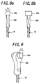
- the coupling part between the end fitting 16a and the cable 16 is advantageously formed with a flat face 16b, as shown in Figs. 8a, 8b, 9, which are in parallel with the short side L 2 of the end fitting 16a.
- this flat face 16b can prevent the end fitting 16a from being rotated around the axis of the cable in the narrow gap 12f, in cooperation with the planar members 12c, 12d, during engaging operation of the end fitting 16a or when the cable 16 has been slackened after completion of engaging of the end fitting 16a. Accordingly, the engaging operation of the end fitting 16a can be facilitated, and the end fitting 16a can be prevented from coming out of the end fitting engaging recesses 12g when the control cable 16 has been slackened.
- the end fitting 16a of the control cable 16 may have any one of various shapes such as a spherical shape having a center located on the axis of the control cable 16 as shown in Fig. 10a, 10b, without departing the above-mentioned concept of the present invention.
Landscapes
- Engineering & Computer Science (AREA)
- General Engineering & Computer Science (AREA)
- Mechanical Engineering (AREA)
- Health & Medical Sciences (AREA)
- Oral & Maxillofacial Surgery (AREA)
- Braking Arrangements (AREA)
- Flexible Shafts (AREA)
Abstract

Description
Claims (12)
- A device for connecting a control cable for use in an operating device comprisinga strut of which one end is engaged with one of members to be operated,a lever which is pivotally journalled to the other end of the strut and is engaged with the other of said members, anda control cable having, at its one end, an end fitting which is adapted to be engaged with a free end of the lever in a cable pulling direction,when applying cable pulling force to a free end of the lever by means of the control cable, the lever and strut being urged to be rotated relative to each other around the journalled portion so as to urge said members to be operated, away from each other, characterized in that:said end fitting of the control cable can be inserted into a position where being between the journalled portion and the free end of the lever in a reverse direction against the cable pulling, and thereafter said end fitting of the control cable can be engaged with the free end of the lever.
- A device for connecting a control cable as set forth in claim 1, characterized in that said lever is composed of a pair of planar members opposed to each other, which planar members are coupled with each other at a portion corresponding to the proximal end of the lever to be pivotally journalled to said other end of the strut, and which planar members are spaced from each other at a portion corresponding to the free end of the lever so as to define a narrow gap between the planar members, having a size which allow a cable itself of the control cable to pass therethrough but which inhibits the end fitting of the control cable from passing therethrough, and to define a wide gap between the planar members at a longitudinally middle portion so as to step down to the narrow gap, having a size which allow the end fitting of the control cable to pass therethrough.
- A device for connecting a control cable as set forth in claim 2, characterized in that the end fitting of the control cable has a shape in which one side is longer than the other side as viewed in the longitudinal direction of the control cable, and the wide gap has a size with which the length of the one side of the end fitting of the control cable can pass through the wide gap.
- A device for connecting a control cable as set forth in claim 2, characterized in that the end fitting of the control cable has a shape in which one side is longer than the other side as viewed in the longitudinal direction of the control cable, and the wide gap has a size with which the length of the other side of the end fitting can pass therethrough, but the length of the one side cannot pass therethrough.
- A device for connecting a control cable as set forth in any one of claims 1 to 4, characterized in that the lever is provided with an end fitting stopper for receiving the end fitting of the control cable upon insertion thereof so as to determine an insertion position thereof, and the strut is provided with a lever abutting part for restricting the rotation of the lever relative to the strut in the direction of insertion of the end fitting of the control cable.
- A device for connecting a control cable as set forth in any one of claims 1 to 4, characterized in that the strut is provided with an end fitting stopper for receiving the end fitting of the control cable upon insertion thereof so as to determine an insertion position thereof.
- A device for connecting a control cable as set forth in any one of claims 1 to 4 and 6, characterized in that there is provided on the strut the lever abutting part for restricting the rotation of the lever relative to the strut in the direction of insertion of the end fitting of the control cable.
- A device for connecting a control cable as set forth in claim 6 or 7, characterized in that said strut is composed of opposed side walls between which the lever is interposed on opposite sides in the direction of the rotational axis of the lever, and a bridge part connecting between the opposed side walls which bridge part serves as the end fitting stopper, the lever abutting parts or both of them.
- A device for connecting a control cable as set forth in claim 8, characterized in that the strut is provided with two bridge parts one of which is arranged in opposition to an intermediate part between the journalled portion and the free end of the lever so as to serve as the end fitting stopper, and the other one of which is located in the vicinity of the journalled portion of the lever so as to serve as the lever abutting part.
- A device for connecting a control cable as set forth in claim 8 or 9, characterized in that said bridge part serving as the end fitting stopper is provided with an end fitting guide piece extended toward the narrow gap.
- A device for connecting a control cable as set forth in claim 10, characterized in that said end fitting guide piece is extended to a position above the narrow gap.
- A device for connecting a control cable as set forth in any one of claims 1 to 11, characterized in that the engagement of the end fitting of the control cable with the free end of the lever is obtained through cylindrical surfaces.
Applications Claiming Priority (2)
| Application Number | Priority Date | Filing Date | Title |
|---|---|---|---|
| JP31178399 | 1999-11-02 | ||
| JP31178399A JP4397080B2 (en) | 1999-11-02 | 1999-11-02 | Operation cable connection device |
Publications (2)
| Publication Number | Publication Date |
|---|---|
| EP1098102A2 true EP1098102A2 (en) | 2001-05-09 |
| EP1098102A3 EP1098102A3 (en) | 2002-01-02 |
Family
ID=18021429
Family Applications (1)
| Application Number | Title | Priority Date | Filing Date |
|---|---|---|---|
| EP00309690A Withdrawn EP1098102A3 (en) | 1999-11-02 | 2000-11-02 | Connecting device for control cable |
Country Status (3)
| Country | Link |
|---|---|
| US (1) | US6715378B1 (en) |
| EP (1) | EP1098102A3 (en) |
| JP (1) | JP4397080B2 (en) |
Cited By (4)
| Publication number | Priority date | Publication date | Assignee | Title |
|---|---|---|---|---|
| EP1265001A3 (en) * | 2001-06-08 | 2003-12-03 | Nisshinbo Industries Inc. | Brake cable connecting apparatus for a drum brake device |
| EP1340659A3 (en) * | 2002-02-19 | 2004-01-14 | Automotive Products (Italia) S.p.A. | Parking brake actuating mechanisms |
| EP1234995A3 (en) * | 2001-02-23 | 2004-01-21 | Nisshinbo Industries Inc. | Apparatus for connecting a brake cable to the actuating lever of a drum brake |
| IT201600105859A1 (en) * | 2016-10-20 | 2018-04-20 | Freni Brembo Spa | Implementation assembly of a parking brake |
Families Citing this family (4)
| Publication number | Priority date | Publication date | Assignee | Title |
|---|---|---|---|---|
| JP4242659B2 (en) * | 2003-02-12 | 2009-03-25 | 日清紡績株式会社 | Brake cable connection device for drum brake |
| US8267227B2 (en) * | 2008-07-22 | 2012-09-18 | Akebono Brake Corporation | Lever assembly featuring blind cable assembly |
| US20110100772A1 (en) * | 2009-11-05 | 2011-05-05 | Akebono Corporation (North America) | Cable end retention clip assembly and method |
| WO2015076783A1 (en) | 2013-11-19 | 2015-05-28 | Kongsberg Driveline Systems I, Inc. | Motion transmitting remote control assembly having a guide mechanism |
Family Cites Families (9)
| Publication number | Priority date | Publication date | Assignee | Title |
|---|---|---|---|---|
| DE1783505U (en) * | 1958-11-21 | 1959-02-19 | Gustav Magenwirth K G | END NIPPLE ON BOWDEN CABLE. |
| DE1253966B (en) * | 1967-02-28 | 1967-11-09 | Teves Kg Alfred | Mechanical spreading device for an inner shoe brake |
| GB8720203D0 (en) * | 1987-08-27 | 1987-10-07 | Lucas Ind Plc | Brake actuator |
| US4930605A (en) * | 1988-11-23 | 1990-06-05 | Orscheln Co. | Brake apparatus with blind cable installing means |
| EP0523054B1 (en) | 1990-03-31 | 1995-06-28 | ALFRED TEVES GmbH | Brake cable fixing for a parking brake, especially for a duo-servo chamber hand-brake |
| DE4307861A1 (en) | 1993-03-12 | 1994-09-15 | Gerhard Spaegele | Expansion lever drum brake for overrun brake devices |
| DE9314350U1 (en) * | 1993-09-22 | 1995-01-26 | Lucas Industries Plc, Solihull, West Midlands | Mechanical actuation device, in particular for motor vehicle brakes |
| US5706914A (en) * | 1997-01-29 | 1998-01-13 | Robert Bosch Technology Corporation | Brake cable lever arm |
| JP4468536B2 (en) | 1999-04-01 | 2010-05-26 | 日清紡ホールディングス株式会社 | Operation cable connection device |
-
1999
- 1999-11-02 JP JP31178399A patent/JP4397080B2/en not_active Expired - Fee Related
-
2000
- 2000-10-31 US US09/699,447 patent/US6715378B1/en not_active Expired - Fee Related
- 2000-11-02 EP EP00309690A patent/EP1098102A3/en not_active Withdrawn
Cited By (7)
| Publication number | Priority date | Publication date | Assignee | Title |
|---|---|---|---|---|
| EP1234995A3 (en) * | 2001-02-23 | 2004-01-21 | Nisshinbo Industries Inc. | Apparatus for connecting a brake cable to the actuating lever of a drum brake |
| EP1265001A3 (en) * | 2001-06-08 | 2003-12-03 | Nisshinbo Industries Inc. | Brake cable connecting apparatus for a drum brake device |
| EP1340659A3 (en) * | 2002-02-19 | 2004-01-14 | Automotive Products (Italia) S.p.A. | Parking brake actuating mechanisms |
| IT201600105859A1 (en) * | 2016-10-20 | 2018-04-20 | Freni Brembo Spa | Implementation assembly of a parking brake |
| WO2018073736A1 (en) * | 2016-10-20 | 2018-04-26 | Freni Brembo S.P.A. | Parking brake actuation assembly |
| CN110073124A (en) * | 2016-10-20 | 2019-07-30 | 福乐尼·乐姆宝公开有限公司 | Parking brake actuating assembly |
| US11428285B2 (en) | 2016-10-20 | 2022-08-30 | Freni Brembo S.P.A. | Parking brake actuation assembly |
Also Published As
| Publication number | Publication date |
|---|---|
| EP1098102A3 (en) | 2002-01-02 |
| JP2001132724A (en) | 2001-05-18 |
| US6715378B1 (en) | 2004-04-06 |
| JP4397080B2 (en) | 2010-01-13 |
Similar Documents
| Publication | Publication Date | Title |
|---|---|---|
| EP1041301B1 (en) | Connecting device for control cable | |
| JP2563935Y2 (en) | Mounting fixture | |
| US4929113A (en) | Knuckle joint | |
| EP1098102A2 (en) | Connecting device for control cable | |
| EP0897441B1 (en) | Couplers | |
| US5820400A (en) | Half-fitting preventing connector | |
| CZ82995A3 (en) | A pair of jaws for mounting onto tongue arms for tightening a sleeve | |
| EP1190921A1 (en) | Blade mounting structure of wiper device | |
| CN101327787B (en) | Cable length adjusting device | |
| JP2001289381A (en) | connector | |
| US6149093A (en) | Tension reducer of a retractor for an automobile safety seat belt | |
| JP4794723B2 (en) | Brake cable connection device | |
| US5979020A (en) | Hose clip and releasing bar tool therefor | |
| EP1234995B1 (en) | Apparatus for connecting a brake cable to the actuating lever of a drum brake | |
| JPH0712153A (en) | Drum brake cable connection method | |
| US6095450A (en) | Pivot for a winding device | |
| GB2207207A (en) | Cable-tension adjuster | |
| JPH0529525Y2 (en) | ||
| JP2571360Y2 (en) | Hose clip | |
| JP3004741U (en) | Eggplant ring | |
| JPS6222675Y2 (en) | ||
| JPS634818Y2 (en) | ||
| JPS6012414Y2 (en) | watch band buckle device | |
| JPH0214552Y2 (en) | ||
| JPH0722504Y2 (en) | Drum brake with automatic shoe clearance adjuster |
Legal Events
| Date | Code | Title | Description |
|---|---|---|---|
| PUAI | Public reference made under article 153(3) epc to a published international application that has entered the european phase |
Free format text: ORIGINAL CODE: 0009012 |
|
| AK | Designated contracting states |
Kind code of ref document: A2 Designated state(s): AT BE CH CY DE DK ES FI FR GB GR IE IT LI LU MC NL PT SE TR Kind code of ref document: A2 Designated state(s): DE GB |
|
| AX | Request for extension of the european patent |
Free format text: AL;LT;LV;MK;RO;SI |
|
| PUAL | Search report despatched |
Free format text: ORIGINAL CODE: 0009013 |
|
| AK | Designated contracting states |
Kind code of ref document: A3 Designated state(s): AT BE CH CY DE DK ES FI FR GB GR IE IT LI LU MC NL PT SE TR |
|
| AX | Request for extension of the european patent |
Free format text: AL;LT;LV;MK;RO;SI |
|
| RIC1 | Information provided on ipc code assigned before grant |
Free format text: 7F 16C 1/14 A, 7F 16D 65/22 B |
|
| 17P | Request for examination filed |
Effective date: 20020618 |
|
| AKX | Designation fees paid |
Free format text: DE FR |
|
| RBV | Designated contracting states (corrected) |
Designated state(s): DE GB |
|
| GRAP | Despatch of communication of intention to grant a patent |
Free format text: ORIGINAL CODE: EPIDOSNIGR1 |
|
| STAA | Information on the status of an ep patent application or granted ep patent |
Free format text: STATUS: THE APPLICATION IS DEEMED TO BE WITHDRAWN |
|
| 18D | Application deemed to be withdrawn |
Effective date: 20041118 |