EP1098084A1 - Fuel flow control device for diaphragm-type carburetor - Google Patents
Fuel flow control device for diaphragm-type carburetor Download PDFInfo
- Publication number
- EP1098084A1 EP1098084A1 EP00123464A EP00123464A EP1098084A1 EP 1098084 A1 EP1098084 A1 EP 1098084A1 EP 00123464 A EP00123464 A EP 00123464A EP 00123464 A EP00123464 A EP 00123464A EP 1098084 A1 EP1098084 A1 EP 1098084A1
- Authority
- EP
- European Patent Office
- Prior art keywords
- valve body
- opening
- lever
- engagement groove
- diaphragm
- Prior art date
- Legal status (The legal status is an assumption and is not a legal conclusion. Google has not performed a legal analysis and makes no representation as to the accuracy of the status listed.)
- Granted
Links
- 239000000446 fuel Substances 0.000 title claims abstract description 49
- 238000000926 separation method Methods 0.000 claims abstract description 5
- 239000002828 fuel tank Substances 0.000 description 5
- 230000037452 priming Effects 0.000 description 4
- 230000000717 retained effect Effects 0.000 description 3
- 239000012530 fluid Substances 0.000 description 2
- 230000002093 peripheral effect Effects 0.000 description 2
- 230000004044 response Effects 0.000 description 2
- 238000010276 construction Methods 0.000 description 1
- 238000004519 manufacturing process Methods 0.000 description 1
- 239000007769 metal material Substances 0.000 description 1
- 229920003002 synthetic resin Polymers 0.000 description 1
- 239000000057 synthetic resin Substances 0.000 description 1
Images

Classifications
-
- F—MECHANICAL ENGINEERING; LIGHTING; HEATING; WEAPONS; BLASTING
- F02—COMBUSTION ENGINES; HOT-GAS OR COMBUSTION-PRODUCT ENGINE PLANTS
- F02M—SUPPLYING COMBUSTION ENGINES IN GENERAL WITH COMBUSTIBLE MIXTURES OR CONSTITUENTS THEREOF
- F02M19/00—Details, component parts, or accessories of carburettors, not provided for in, or of interest apart from, the apparatus of groups F02M1/00 - F02M17/00
- F02M19/04—Fuel-metering pins or needles
-
- F—MECHANICAL ENGINEERING; LIGHTING; HEATING; WEAPONS; BLASTING
- F02—COMBUSTION ENGINES; HOT-GAS OR COMBUSTION-PRODUCT ENGINE PLANTS
- F02M—SUPPLYING COMBUSTION ENGINES IN GENERAL WITH COMBUSTIBLE MIXTURES OR CONSTITUENTS THEREOF
- F02M17/00—Carburettors having pertinent characteristics not provided for in, or of interest apart from, the apparatus of preceding main groups F02M1/00 - F02M15/00
- F02M17/02—Floatless carburettors
- F02M17/04—Floatless carburettors having fuel inlet valve controlled by diaphragm
-
- F—MECHANICAL ENGINEERING; LIGHTING; HEATING; WEAPONS; BLASTING
- F02—COMBUSTION ENGINES; HOT-GAS OR COMBUSTION-PRODUCT ENGINE PLANTS
- F02M—SUPPLYING COMBUSTION ENGINES IN GENERAL WITH COMBUSTIBLE MIXTURES OR CONSTITUENTS THEREOF
- F02M5/00—Float-controlled apparatus for maintaining a constant fuel level
- F02M5/12—Other details, e.g. floats, valves, setting devices or tools
- F02M5/125—Shape of the jet needle
-
- Y—GENERAL TAGGING OF NEW TECHNOLOGICAL DEVELOPMENTS; GENERAL TAGGING OF CROSS-SECTIONAL TECHNOLOGIES SPANNING OVER SEVERAL SECTIONS OF THE IPC; TECHNICAL SUBJECTS COVERED BY FORMER USPC CROSS-REFERENCE ART COLLECTIONS [XRACs] AND DIGESTS
- Y10—TECHNICAL SUBJECTS COVERED BY FORMER USPC
- Y10S—TECHNICAL SUBJECTS COVERED BY FORMER USPC CROSS-REFERENCE ART COLLECTIONS [XRACs] AND DIGESTS
- Y10S261/00—Gas and liquid contact apparatus
- Y10S261/68—Diaphragm-controlled inlet valve
-
- Y—GENERAL TAGGING OF NEW TECHNOLOGICAL DEVELOPMENTS; GENERAL TAGGING OF CROSS-SECTIONAL TECHNOLOGIES SPANNING OVER SEVERAL SECTIONS OF THE IPC; TECHNICAL SUBJECTS COVERED BY FORMER USPC CROSS-REFERENCE ART COLLECTIONS [XRACs] AND DIGESTS
- Y10—TECHNICAL SUBJECTS COVERED BY FORMER USPC
- Y10T—TECHNICAL SUBJECTS COVERED BY FORMER US CLASSIFICATION
- Y10T137/00—Fluid handling
- Y10T137/7722—Line condition change responsive valves
- Y10T137/7781—With separate connected fluid reactor surface
- Y10T137/7793—With opening bias [e.g., pressure regulator]
- Y10T137/7831—With mechanical movement between actuator and valve
Definitions
- the present invention relates generally to a diaphragm-type carburetor and more particularly to a fuel flow control device for a diaphragm-type carburetor.
- a fuel flow control valve opens and closes in response to the movement of a diaphragm to admit fuel into a fuel chamber and maintain fuel therein under a substantially constant pressure.
- a lever is pivotably supported on a shaft within the fuel chamber.
- One end of the lever is biased and abutted against the diaphragm by means of a spring, and the other end of the lever engages a valve body of the flow control valve.
- FIG. 5 shows one such lever 55 of a conventional carburetor.
- the lever has a cut-out 80 at one end thereof to define a pair of left and right arms. The clearance between the arms is larger than the diameter of a circumferential engagement groove 72 (FIG.
- the lever can become disengaged from the groove 72 when the lever is in an inclined position, particularly, when a subassembly including the lever and the flow control valve body is mounted in the constant pressure fuel chamber of the carburetor.
- the fuel flow control device embodying the invention has a constant pressure fuel chamber defined in part by a fuel metering diaphragm with a pivotably mounted lever therein actuated by the diaphragm and coupled to a valve body so that it cannot become disengaged in use.
- One end of the lever is biased and abutted with the diaphragm preferably by a spring.
- the flow control valve body is operably connected to the other end of the lever for movement relative to a valve seat between open and closed positions to control fluid flow through an inlet passage leading to the constant pressure fuel chamber.
- the end of the lever coupled to the valve body preferably has a boss and a pair of arms extending perpendicular to the boss. A top plate having an opening is fitted on the lever on or between the pair of arms.
- the opening of the top plate is adapted to receive the valve body in the area of a circumferential engagement groove formed in the valve body.
- the top plate has a pair of spaced apart and generally opposed resilient hook pieces with a clearance or gap between them which is smaller then the diameter of the valve body in the area of the engagement groove.
- the hook pieces are at least somewhat flexible to permit the valve body to pass thereby into the opening in the top plate and are resilient so that they return to their unflexed position after the valve body passes to maintain the valve body in the opening. In this manner, unintended disengagement or separation of the lever and valve body is prevented in use of the carburetor.
- the lever has a circumferentially continuous opening of a smaller diameter than an end portion of the valve body and slightly larger diameter than the valve body in the engagement groove.
- the lever is somewhat flexible and resilient in the area of the opening and flexes to permit the end portion of the valve body to pass thereby disposing the engagement groove in the opening. Thereafter, the flexed portion of the lever preferably returns sufficiently towards its unflexed orientation to prevent the end portion from passing thereby in use of the valve assembly. This prevents unintended separation of the lever and valve body.
- Objects, features and advantages of this invention include providing a fuel flow control device which is easy to assembly, is easy to install in a carburetor, prevents separation of a lever and valve body in use, provides a smooth operation and movement of the valve body, is reliable, durable, of relatively simple design and economical manufacture and assembly and in service has a long useful life.
- FIG. 1 illustrates a carburetor 11 having a cylindrical valve chamber 19 which engagedly receives a rotary throttle valve 20 having a throttle opening 22.
- the throttle valve 20 can rotate around its central axis and is vertically slidably movable in valve chamber 19.
- the throttle valve 20 has a shaft 15 at a top end thereof and supported on a cover plate 16 which closes the cylindrical valve chamber 19.
- the shaft 15 is coupled to a throttle lever 12 which has a lower inclined cam surface 13.
- the cam surface 13 engages with a ball 14 retained on the cover plate 16 by the resilient force of a return spring 18.
- the shaft 15 holds a rod valve 21 adjustably threaded and screwed into the shaft 15.
- the rod valve 21 extends into a throttle opening 22 of the rotary throttle valve 20 and is slidably received in a fuel feed pipe 39.
- the throttle lever 12 rotates the throttle valve 20 and changes the degree or extent to which the throttle opening 22 communicates with an air intake passage (not shown) extending axially through the carburetor body 17.
- the throttle valve 20 moves vertically together with the rod valve 21 due to the engagement of the cam surface 13 with the ball 14, so that the open area of a fuel jet hole 39a of the fuel feed pipe 39 is adjusted.
- the fuel feed pipe is engaged with and is supported by a central cylindrical portion 23 disposed on a bottom of the cylindrical valve chamber 19.
- the fuel feed pipe 39 communicates with a constant pressure fuel chamber 35 of a constant pressure fuel supply assembly B by way of a fuel jet 51 and a check valve 36.
- the constant pressure fuel supply assembly B having the constant pressure chamber 35 is provided with a diaphragm 41 sandwiched between an intermediate plate 49 and a cover 50.
- the diaphragm partially defines the constant pressure chamber 35 on one side and an atmospheric chamber 42 on its other side.
- a lever 34 is supposed by a support shaft 33 within the constant pressure chamber 35.
- the lever 34 is resiliently biased at one end thereof by a spring 31 retained in a pocket of plate 49 and on a protrusion 62 of the lever 34. Meanwhile, the other end of the lever 34 is coupled to a poppet-type flow control valve body 70.
- Fuel is supplied from a fuel tank 2 to the constant pressure chamber 35 through a fuel pump A and a metering valve assembly with a fuel flow control valve body 70.
- the fuel pump A and the constant pressure chamber 35 also communicate with a manual priming pump 44.
- the priming pump 44 communicates with the chamber 35 by way of a passage 43, an inlet check valve 45 provided at a peripheral flange of a mushroom-shaped valve body, an inner space defined by a transfer pipet or flexible rubber dome 48 of the priming pump 44; and with the fuel tank 2 through an outlet check valve 46 provided around a central axis of the mushroom-shaped valve body, and a passage 47.
- the priming pump 44 is operated by manually pressing and releasing the dome 48 to discharge any air in the constant pressure chamber 35 and fuel pump A into the fuel tank 2. Thereby, fuel in the fuel tank 2 is drawn into the constant pressure chamber 35 through a passage 3, the fuel pump A, and the flow control valve body 70.
- the fuel pump A has a diaphragm 25 sandwiched between the carburetor main body 17 and the intermediate plate 49.
- the diaphragm 25 defines partially a pump chamber 7 and a pressure pulse chamber 24.
- the pressure pulse chamber 24 communicates with a crankcase chamber of the engine (or with a portion of the air intake passage downstream of the throttle valve) to receive fluctuating pressure pulses of the crankcase chamber which actuate and displace the diaphragm 25.
- the alternate upward and downward movement of the diaphragm 25 produced by the pressure pulses draws fuel from the fuel tank 2 into the pump chamber 7 through the passage 3, an inlet check valve 5, and a passage 6.
- the fuel in the pump chamber 7 is discharged into the constant pressure chamber 35 through an outlet check valve 8, a discharge passage 9, an inlet passage 10, and the valve body 70.
- the diaphragm 41 moves downward so that the lever 34 moves or lifts the valve body 70 to close the end of the inlet passage 10 and prevent or at least substantially restrict fluid flow into the fuel chamber 35.
- the constant pressure fuel chamber 35 keeps fuel therein under a substantially constant pressure.
- the lever 34 has a tube or boss 63 formed with a shaft hole 63a for rotatably receiving the aforementioned support shaft 33.
- an arm part 66 consisting of a pair of plate-shaped, left and right arms 64 axially spaced from each other.
- Each arm 64 has a root portion crossing the boss 63.
- a lever piece 61 is joined unitarily to the root portions of the arms 64.
- the lever piece 61 has the protrusion 62 extending from an upper surface thereof which retains one end of the spring 31 to prevent lateral shifting of the spring 31.
- a top plate 75 which is formed with a semi-circular opening 68 at an inner part of top plate 75. The opening 68 cooperates with and receives a circumferential engagement groove 72 formed in the valve body 70.
- the opening 68 has a narrowed entrance defined between a pair of left and right resilient hook or detent pieces 65.
- the resilient hook pieces 65 are preferably each integrally formed with the top plate 75 and are positioned near the outer or free end of each arm 64.
- the clearance between the resilient hook pieces 65 is smaller than the inner diameter of the opening 68 and also is smaller than the diameter of the valve body 70 in the engagement groove 72.
- the valve body 70 has a tapered or conical valve head 74 at one end which engages with and disengages from a valve seat at the inlet passage 10 of the carburetor body 17 for opening and closing and thus controlling fuel flow through the inlet passage 10.
- the valve body 70 also has a middle sliding portion 73 slidably received in a cylindrical valve hole formed in the intermediate plate 49.
- the sliding portion 73 is a circular column having flat outer surfaces formed by axially cutting a portion of the peripheral surface of the circular column.
- At the other end of the valve body 70 there is formed the circumferential engagement groove 72 and an end portion 71 of a short column.
- the lever 34 and valve body 70 can each be a separate single piece unitarily molded or otherwise formed from a synthetic resin or a metal material.
- valve body 70 To connect the valve body 70 to the lever 34, in the area of engagement groove 72 the valve body 70 is forced into the gap between the pair of resilient hook pieces 65 toward the opening 68 to flex the hook pieces outwardly, away from each other, and thereby increase the gap between them.
- the outwardly flexed hook pieces 65 allow the valve body 70 to enter the opening 68.
- the resilient hook pieces 65 After the valve body 70 passes the hook pieces 65, the resilient hook pieces 65 return to their original unflexed position to reduce the gap between them and provide the normal clearance which is smaller than the diameter of the valve body 70 in the engagement groove 72. This prevents the disengagement of the lever 34 from the valve body 70 during use of the carburetor and particularly when mounting a subassembly of the valve body 70 and the lever 34 into the carburetor.
- the lever 34 has the pair of resilient hook pieces or detents 65 at one end thereof so that each resilient hook piece 65 can flex outwardly to permit the valve body 70 in the area of the engagement groove 72 to pass between them and into the opening 68.
- the entrance or clearance between the hook pieces 65 when they are unflexed is smaller than the diameter of the opening 68 provided inside of the hook pieces 65 and is smaller than the diameter of valve body 70 in the engagement groove 72.
- an appropriate gap is provided between the engagement groove 72 of the valve body 70 and the lever opening 68 in assembly. This enables a smooth vertical movement of the valve body 70 in response to the pivoting of the lever 34, allowing a reliable operation of the valve body 70.
- a lever 34' does not have an entrance clearance as described above but has a completely circular or circumferentially continuous opening 67 slightly smaller than the diameter of the end portion 71 of the valve body 70.
- the end portion 71 of the valve body 70 is forced axially into the opening 67 and resiliently flexes the lever in the area of or at the edge of the opening 67 to permit the end portion 71 to pass through the opening 67 thereby disposing the engagement groove 72 in opening 67.
- the flexed area or edge of the opening 67 After permitting end portion 71 to pass therethrough, the flexed area or edge of the opening 67 returns at least in part toward its unflexed position so that the opening 67 has a diameter smaller than the diameter of the end portion 71 and larger than the minimum diameter of the engagement groove 72 of the valve body 70 so that the lever is retained in the engagement groove 72. This construction also prevents the disengagement of the received valve body 70 from the lever 34'.
Abstract
Description
- The present invention relates generally to a diaphragm-type carburetor and more particularly to a fuel flow control device for a diaphragm-type carburetor.
- In a conventional diaphragm-type carburetor, a fuel flow control valve opens and closes in response to the movement of a diaphragm to admit fuel into a fuel chamber and maintain fuel therein under a substantially constant pressure. To accomplish this, a lever is pivotably supported on a shaft within the fuel chamber. One end of the lever is biased and abutted against the diaphragm by means of a spring, and the other end of the lever engages a valve body of the flow control valve. FIG. 5 shows one such lever 55 of a conventional carburetor. The lever has a cut-out 80 at one end thereof to define a pair of left and right arms. The clearance between the arms is larger than the diameter of a circumferential engagement groove 72 (FIG. 2) formed in an outer surface of the valve body of the flow control valve. Undesirably, the lever can become disengaged from the
groove 72 when the lever is in an inclined position, particularly, when a subassembly including the lever and the flow control valve body is mounted in the constant pressure fuel chamber of the carburetor. - An improved fuel flow control device of a diaphragm-type carburetor having a lever which can be easily coupled to a flow control valve body and cannot become disengaged from the flow control valve body in use and has a reliable and repeatable operational movement.
- The fuel flow control device embodying the invention has a constant pressure fuel chamber defined in part by a fuel metering diaphragm with a pivotably mounted lever therein actuated by the diaphragm and coupled to a valve body so that it cannot become disengaged in use. One end of the lever is biased and abutted with the diaphragm preferably by a spring. The flow control valve body is operably connected to the other end of the lever for movement relative to a valve seat between open and closed positions to control fluid flow through an inlet passage leading to the constant pressure fuel chamber. The end of the lever coupled to the valve body preferably has a boss and a pair of arms extending perpendicular to the boss. A top plate having an opening is fitted on the lever on or between the pair of arms. The opening of the top plate is adapted to receive the valve body in the area of a circumferential engagement groove formed in the valve body. The top plate has a pair of spaced apart and generally opposed resilient hook pieces with a clearance or gap between them which is smaller then the diameter of the valve body in the area of the engagement groove. The hook pieces are at least somewhat flexible to permit the valve body to pass thereby into the opening in the top plate and are resilient so that they return to their unflexed position after the valve body passes to maintain the valve body in the opening. In this manner, unintended disengagement or separation of the lever and valve body is prevented in use of the carburetor.
- In another form, the lever has a circumferentially continuous opening of a smaller diameter than an end portion of the valve body and slightly larger diameter than the valve body in the engagement groove. The lever is somewhat flexible and resilient in the area of the opening and flexes to permit the end portion of the valve body to pass thereby disposing the engagement groove in the opening. Thereafter, the flexed portion of the lever preferably returns sufficiently towards its unflexed orientation to prevent the end portion from passing thereby in use of the valve assembly. This prevents unintended separation of the lever and valve body.
- Objects, features and advantages of this invention include providing a fuel flow control device which is easy to assembly, is easy to install in a carburetor, prevents separation of a lever and valve body in use, provides a smooth operation and movement of the valve body, is reliable, durable, of relatively simple design and economical manufacture and assembly and in service has a long useful life.
- These and other objects, features and advantages of this invention will be apparent from the following detailed description of the preferred embodiments and best mode, appended claims and accompanying drawings in which:
- FIG. 1 is a front sectional view showing a carburetor having a diaphragm-actuated fuel control device according to the present invention;
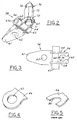
- FIG. 2 is a perspective view showing an assembly of a lever and a flow control valve of the fuel control device;
- FIG. 3 is a bottom view showing the lever of the fuel control device;
- FIG. 4 is a fragmentary perspective view showing a primary part of an lever of a fuel control device according to an alternate embodiment of the present invention; and
- FIG. 5 is a fragmentary perspective view showing a primary part of a lever of a conventional diaphragm-actuated fuel control device of a carburetor according to the prior art.
-
- Referring in more detail to the drawings, FIG. 1 illustrates a carburetor 11 having a
cylindrical valve chamber 19 which engagedly receives arotary throttle valve 20 having a throttle opening 22. Thethrottle valve 20 can rotate around its central axis and is vertically slidably movable invalve chamber 19. Thethrottle valve 20 has ashaft 15 at a top end thereof and supported on acover plate 16 which closes thecylindrical valve chamber 19. Theshaft 15 is coupled to athrottle lever 12 which has a lowerinclined cam surface 13. Thecam surface 13 engages with aball 14 retained on thecover plate 16 by the resilient force of areturn spring 18. Theshaft 15 holds a rod valve 21 adjustably threaded and screwed into theshaft 15. The rod valve 21 extends into a throttle opening 22 of therotary throttle valve 20 and is slidably received in afuel feed pipe 39. - Turning the
throttle lever 12 by a remote trigger lever (not shown) rotates thethrottle valve 20 and changes the degree or extent to which the throttle opening 22 communicates with an air intake passage (not shown) extending axially through thecarburetor body 17. At the same time, thethrottle valve 20 moves vertically together with the rod valve 21 due to the engagement of thecam surface 13 with theball 14, so that the open area of afuel jet hole 39a of thefuel feed pipe 39 is adjusted. The fuel feed pipe is engaged with and is supported by a central cylindrical portion 23 disposed on a bottom of thecylindrical valve chamber 19. Thefuel feed pipe 39 communicates with a constantpressure fuel chamber 35 of a constant pressure fuel supply assembly B by way of afuel jet 51 and acheck valve 36. - The constant pressure fuel supply assembly B having the
constant pressure chamber 35 is provided with adiaphragm 41 sandwiched between anintermediate plate 49 and acover 50. The diaphragm partially defines theconstant pressure chamber 35 on one side and anatmospheric chamber 42 on its other side. Alever 34 is supposed by asupport shaft 33 within theconstant pressure chamber 35. Thelever 34 is resiliently biased at one end thereof by a spring 31 retained in a pocket ofplate 49 and on aprotrusion 62 of thelever 34. Meanwhile, the other end of thelever 34 is coupled to a poppet-type flowcontrol valve body 70. - Fuel is supplied from a fuel tank 2 to the
constant pressure chamber 35 through a fuel pump A and a metering valve assembly with a fuel flowcontrol valve body 70. The fuel pump A and theconstant pressure chamber 35 also communicate with a manual priming pump 44. The priming pump 44 communicates with thechamber 35 by way of apassage 43, aninlet check valve 45 provided at a peripheral flange of a mushroom-shaped valve body, an inner space defined by a transfer pipet orflexible rubber dome 48 of the priming pump 44; and with the fuel tank 2 through anoutlet check valve 46 provided around a central axis of the mushroom-shaped valve body, and apassage 47. Before cranking or starting an associated engine, the priming pump 44 is operated by manually pressing and releasing thedome 48 to discharge any air in theconstant pressure chamber 35 and fuel pump A into the fuel tank 2. Thereby, fuel in the fuel tank 2 is drawn into theconstant pressure chamber 35 through a passage 3, the fuel pump A, and the flowcontrol valve body 70. - The fuel pump A has a
diaphragm 25 sandwiched between the carburetormain body 17 and theintermediate plate 49. Thediaphragm 25 defines partially a pump chamber 7 and apressure pulse chamber 24. Thepressure pulse chamber 24 communicates with a crankcase chamber of the engine (or with a portion of the air intake passage downstream of the throttle valve) to receive fluctuating pressure pulses of the crankcase chamber which actuate and displace thediaphragm 25. The alternate upward and downward movement of thediaphragm 25 produced by the pressure pulses draws fuel from the fuel tank 2 into the pump chamber 7 through the passage 3, aninlet check valve 5, and a passage 6. The fuel in the pump chamber 7 is discharged into theconstant pressure chamber 35 through an outlet check valve 8, adischarge passage 9, aninlet passage 10, and thevalve body 70. When the constantpressure fuel chamber 35 is filled with the fuel, thediaphragm 41 moves downward so that thelever 34 moves or lifts thevalve body 70 to close the end of theinlet passage 10 and prevent or at least substantially restrict fluid flow into thefuel chamber 35. Thereby, the constantpressure fuel chamber 35 keeps fuel therein under a substantially constant pressure. - As shown in FIG. 2, the
lever 34 has a tube orboss 63 formed with ashaft hole 63a for rotatably receiving theaforementioned support shaft 33. Preferably integral with theboss 63, there is provided anarm part 66 consisting of a pair of plate-shaped, left andright arms 64 axially spaced from each other. Eacharm 64 has a root portion crossing theboss 63. Alever piece 61 is joined unitarily to the root portions of thearms 64. Thelever piece 61 has theprotrusion 62 extending from an upper surface thereof which retains one end of the spring 31 to prevent lateral shifting of the spring 31. Between the pair ofarms 64, there is provided atop plate 75 which is formed with asemi-circular opening 68 at an inner part oftop plate 75. Theopening 68 cooperates with and receives acircumferential engagement groove 72 formed in thevalve body 70. - As illustrated in FIG. 3, the
opening 68 has a narrowed entrance defined between a pair of left and right resilient hook ordetent pieces 65. Theresilient hook pieces 65 are preferably each integrally formed with thetop plate 75 and are positioned near the outer or free end of eacharm 64. The clearance between theresilient hook pieces 65 is smaller than the inner diameter of theopening 68 and also is smaller than the diameter of thevalve body 70 in theengagement groove 72. - As best shown in FIG. 2, the
valve body 70 has a tapered orconical valve head 74 at one end which engages with and disengages from a valve seat at theinlet passage 10 of thecarburetor body 17 for opening and closing and thus controlling fuel flow through theinlet passage 10. Thevalve body 70 also has amiddle sliding portion 73 slidably received in a cylindrical valve hole formed in theintermediate plate 49. The slidingportion 73 is a circular column having flat outer surfaces formed by axially cutting a portion of the peripheral surface of the circular column. At the other end of thevalve body 70, there is formed thecircumferential engagement groove 72 and anend portion 71 of a short column. Thelever 34 andvalve body 70 can each be a separate single piece unitarily molded or otherwise formed from a synthetic resin or a metal material. - To connect the
valve body 70 to thelever 34, in the area ofengagement groove 72 thevalve body 70 is forced into the gap between the pair ofresilient hook pieces 65 toward theopening 68 to flex the hook pieces outwardly, away from each other, and thereby increase the gap between them. The outwardly flexedhook pieces 65 allow thevalve body 70 to enter theopening 68. After thevalve body 70 passes thehook pieces 65, theresilient hook pieces 65 return to their original unflexed position to reduce the gap between them and provide the normal clearance which is smaller than the diameter of thevalve body 70 in theengagement groove 72. This prevents the disengagement of thelever 34 from thevalve body 70 during use of the carburetor and particularly when mounting a subassembly of thevalve body 70 and thelever 34 into the carburetor. - In the preferred embodiment as described, the
lever 34 has the pair of resilient hook pieces ordetents 65 at one end thereof so that eachresilient hook piece 65 can flex outwardly to permit thevalve body 70 in the area of theengagement groove 72 to pass between them and into theopening 68. The entrance or clearance between thehook pieces 65 when they are unflexed is smaller than the diameter of theopening 68 provided inside of thehook pieces 65 and is smaller than the diameter ofvalve body 70 in theengagement groove 72. Thus, when thevalve body 70 is received in theopening 68 as described, there is no possibility of inadvertent or unintended disengagement from thelever 34. Desirably, an appropriate gap is provided between theengagement groove 72 of thevalve body 70 and thelever opening 68 in assembly. This enables a smooth vertical movement of thevalve body 70 in response to the pivoting of thelever 34, allowing a reliable operation of thevalve body 70. - As shown in FIG. 4, a lever 34' according to an alternate embodiment of the invention does not have an entrance clearance as described above but has a completely circular or circumferentially
continuous opening 67 slightly smaller than the diameter of theend portion 71 of thevalve body 70. In this embodiment, theend portion 71 of thevalve body 70 is forced axially into theopening 67 and resiliently flexes the lever in the area of or at the edge of theopening 67 to permit theend portion 71 to pass through theopening 67 thereby disposing theengagement groove 72 inopening 67. After permittingend portion 71 to pass therethrough, the flexed area or edge of theopening 67 returns at least in part toward its unflexed position so that theopening 67 has a diameter smaller than the diameter of theend portion 71 and larger than the minimum diameter of theengagement groove 72 of thevalve body 70 so that the lever is retained in theengagement groove 72. This construction also prevents the disengagement of the receivedvalve body 70 from the lever 34'.
Claims (9)
- A fuel flow control device for a carburetor having a diaphragm defining at least in part a constant pressure fuel chamber, said device comprising:a valve body having a reduced diameter engagement groove and a valve head and being movable between open and closed positions to control fuel flow into the constant pressure fuel chamber; anda lever having opposed ends, pivotably carried by the carburetor between its ends, communicated with the diaphragm at one end to be responsive to movement of the diaphragm and having an opening adjacent to its other end defined at least in part by a resilient portion and having an effective size smaller than a portion of the valve body inserted into the opening with said resilient portion being flexible to permit said portion of the valve body to pass thereby to dispose the engagement groove in the opening and thereafter said resilient portion returns at least in part toward its unflexed state to prevent said portion of the valve body from freely passing thereby to prevent inadvertent separation of the valve body and lever.
- The device of claim 1 wherein the resilient portion comprises a pair of spaced apart resilient hook pieces having a gap between them when they are not flexed which is smaller than the diameter of the valve body in the engagement groove and can be flexed to permit the valve body in the area of the engagement groove to pass between the hook pieces.
- The device of claim 1 which also comprises an end portion of the valve body of larger diameter than the engagement groove and wherein the opening is of smaller diameter than the end portion of the valve body and the resilient portion comprises an edge of the opening which flexes to permit the end of the valve body to pass into the opening.
- The device of claim 3 wherein the opening is circumferentially continuous.
- The device of claim 2 wherein the lever also comprises a boss with a shaft hole, a pair of arms extending perpendicular to the boss and a top plate disposed on the arms and through which the opening is defined, said hooks being carried by the top plate.
- The device of claim 5 wherein the hooks are integral with the top plate.
- The device of claim 5 wherein the boss, arms and top plate are integrally formed on the lever.
- The device of claim 5 which also comprises a support shaft disposed in the shaft hole carried by the carburetor and about which the lever pivots.
- The device of claim 1 wherein the opening is slightly larger than the valve body in the engagement groove to provide a gap between them.
Applications Claiming Priority (2)
| Application Number | Priority Date | Filing Date | Title |
|---|---|---|---|
| JP31384899 | 1999-11-04 | ||
| JP31384899A JP2001132545A (en) | 1999-11-04 | 1999-11-04 | Fuel regulating mechanism for diaphragm carburetor |
Publications (2)
| Publication Number | Publication Date |
|---|---|
| EP1098084A1 true EP1098084A1 (en) | 2001-05-09 |
| EP1098084B1 EP1098084B1 (en) | 2002-09-11 |
Family
ID=18046247
Family Applications (1)
| Application Number | Title | Priority Date | Filing Date |
|---|---|---|---|
| EP00123464A Expired - Lifetime EP1098084B1 (en) | 1999-11-04 | 2000-11-06 | Fuel flow control device for diaphragm-type carburetor |
Country Status (4)
| Country | Link |
|---|---|
| US (1) | US6382598B1 (en) |
| EP (1) | EP1098084B1 (en) |
| JP (1) | JP2001132545A (en) |
| DE (1) | DE60000430T2 (en) |
Cited By (1)
| Publication number | Priority date | Publication date | Assignee | Title |
|---|---|---|---|---|
| US7261281B2 (en) | 2004-12-21 | 2007-08-28 | Andreas Stihl Ag & Co. Kg | Carburetor |
Families Citing this family (2)
| Publication number | Priority date | Publication date | Assignee | Title |
|---|---|---|---|---|
| US6715737B2 (en) | 2000-08-29 | 2004-04-06 | Walbro Corporation | Fuel metering system for a carburetor |
| SE1751610A1 (en) * | 2015-06-25 | 2017-12-21 | Walbro Llc | Rotary throttle valve and carburetor |
Citations (1)
| Publication number | Priority date | Publication date | Assignee | Title |
|---|---|---|---|---|
| US5681508A (en) * | 1995-03-18 | 1997-10-28 | Andreas Stihl | Diaphragm carburetor for an internal combustion engine |
Family Cites Families (9)
| Publication number | Priority date | Publication date | Assignee | Title |
|---|---|---|---|---|
| US3133129A (en) * | 1958-06-02 | 1964-05-12 | Tillotson Mfg Co | Charge forming device for internal combustion engines |
| US3377024A (en) * | 1964-05-19 | 1968-04-09 | Tillotson Mfg Co | Liquid fuel burner system and fuel control |
| US3404872A (en) * | 1966-05-25 | 1968-10-08 | Tillotson Mfg Co | Charge forming apparatus |
| US3992490A (en) * | 1972-08-03 | 1976-11-16 | Borg-Warner Corporation | Method and means of adjustment control for charge forming apparatus |
| US4003968A (en) * | 1973-06-01 | 1977-01-18 | Borg-Warner Corporation | Charge forming method and apparatus |
| US4563311A (en) * | 1984-02-23 | 1986-01-07 | Mcculloch Corporation | Carburetor valve |
| US5288013A (en) * | 1993-01-05 | 1994-02-22 | Olympic Packaging, Inc. | Carton with partial end panels |
| JP3730785B2 (en) * | 1998-07-28 | 2006-01-05 | 本田技研工業株式会社 | Floatless type vaporizer |
| JP2000045876A (en) * | 1998-07-28 | 2000-02-15 | Honda Motor Co Ltd | Floatless type carburetor |
-
1999
- 1999-11-04 JP JP31384899A patent/JP2001132545A/en active Pending
-
2000
- 2000-10-25 US US09/696,487 patent/US6382598B1/en not_active Expired - Fee Related
- 2000-11-06 EP EP00123464A patent/EP1098084B1/en not_active Expired - Lifetime
- 2000-11-06 DE DE60000430T patent/DE60000430T2/en not_active Expired - Fee Related
Patent Citations (1)
| Publication number | Priority date | Publication date | Assignee | Title |
|---|---|---|---|---|
| US5681508A (en) * | 1995-03-18 | 1997-10-28 | Andreas Stihl | Diaphragm carburetor for an internal combustion engine |
Cited By (2)
| Publication number | Priority date | Publication date | Assignee | Title |
|---|---|---|---|---|
| US7261281B2 (en) | 2004-12-21 | 2007-08-28 | Andreas Stihl Ag & Co. Kg | Carburetor |
| DE102004061397B4 (en) * | 2004-12-21 | 2015-06-11 | Andreas Stihl Ag & Co. Kg | Roller carburetor with air duct and mixture channel |
Also Published As
| Publication number | Publication date |
|---|---|
| EP1098084B1 (en) | 2002-09-11 |
| US6382598B1 (en) | 2002-05-07 |
| DE60000430T2 (en) | 2003-08-07 |
| DE60000430D1 (en) | 2002-10-17 |
| JP2001132545A (en) | 2001-05-15 |
Similar Documents
| Publication | Publication Date | Title |
|---|---|---|
| US5507318A (en) | Umbrella check valves | |
| AU593967B2 (en) | Primer system and method for priming an internal combustion engine | |
| CA1271674A (en) | Carburetor with self seating needle valve | |
| US6672570B2 (en) | Variable venturi carburetor | |
| US6536747B2 (en) | Carburetor vent control | |
| EP0247276B1 (en) | Carburation system for an internal combustion engine | |
| EP1098084B1 (en) | Fuel flow control device for diaphragm-type carburetor | |
| EP0401480B1 (en) | Primer bulb check valve system for an internally vented bowl primer carburetor | |
| JPH0295768A (en) | Fuel conditioning unit for internal combustion engine | |
| US4197825A (en) | Primer bulb retainer | |
| US3089685A (en) | Carburetor | |
| JPH01147149A (en) | Starting fuel feeder for carburetor | |
| US7287743B1 (en) | Carburetor with an air bleed passage | |
| US20040017014A1 (en) | Rotary throttle valve carburetor | |
| US6827337B2 (en) | Rotary throttle valve carburetor | |
| US4228110A (en) | Gasoline priming pump for carburetors | |
| US8539991B1 (en) | Vapor recovery fuel dispensing nozzle | |
| JPS6027837Y2 (en) | Connection device between diaphragm and operating rod | |
| US20030047818A1 (en) | Fuel metering assembly for a diaphragm-type carburetor | |
| WO2006049946A1 (en) | Accelerator pump cap for a motorcycle carburetor | |
| US5318062A (en) | Readily serviceable differential pressure actuated ballcock valve | |
| US4743171A (en) | Marine installation including fuel/oil mixing device | |
| US4305368A (en) | Apparatus for venting fuel vapors | |
| JPH11247719A (en) | Diaphragm-type carburetor | |
| US3485483A (en) | Downdraft carburetor |
Legal Events
| Date | Code | Title | Description |
|---|---|---|---|
| PUAI | Public reference made under article 153(3) epc to a published international application that has entered the european phase |
Free format text: ORIGINAL CODE: 0009012 |
|
| AK | Designated contracting states |
Kind code of ref document: A1 Designated state(s): DE IT SE |
|
| AX | Request for extension of the european patent |
Free format text: AL;LT;LV;MK;RO;SI |
|
| GRAG | Despatch of communication of intention to grant |
Free format text: ORIGINAL CODE: EPIDOS AGRA |
|
| 17P | Request for examination filed |
Effective date: 20011109 |
|
| AKX | Designation fees paid |
Free format text: DE IT SE |
|
| 17Q | First examination report despatched |
Effective date: 20020107 |
|
| GRAG | Despatch of communication of intention to grant |
Free format text: ORIGINAL CODE: EPIDOS AGRA |
|
| GRAH | Despatch of communication of intention to grant a patent |
Free format text: ORIGINAL CODE: EPIDOS IGRA |
|
| GRAH | Despatch of communication of intention to grant a patent |
Free format text: ORIGINAL CODE: EPIDOS IGRA |
|
| GRAA | (expected) grant |
Free format text: ORIGINAL CODE: 0009210 |
|
| AK | Designated contracting states |
Kind code of ref document: B1 Designated state(s): DE IT SE |
|
| REF | Corresponds to: |
Ref document number: 60000430 Country of ref document: DE Date of ref document: 20021017 |
|
| PLBE | No opposition filed within time limit |
Free format text: ORIGINAL CODE: 0009261 |
|
| STAA | Information on the status of an ep patent application or granted ep patent |
Free format text: STATUS: NO OPPOSITION FILED WITHIN TIME LIMIT |
|
| 26N | No opposition filed |
Effective date: 20030612 |
|
| PGFP | Annual fee paid to national office [announced via postgrant information from national office to epo] |
Ref country code: SE Payment date: 20031121 Year of fee payment: 4 |
|
| PGFP | Annual fee paid to national office [announced via postgrant information from national office to epo] |
Ref country code: DE Payment date: 20031231 Year of fee payment: 4 |
|
| PG25 | Lapsed in a contracting state [announced via postgrant information from national office to epo] |
Ref country code: SE Free format text: LAPSE BECAUSE OF NON-PAYMENT OF DUE FEES Effective date: 20041107 |
|
| PG25 | Lapsed in a contracting state [announced via postgrant information from national office to epo] |
Ref country code: DE Free format text: LAPSE BECAUSE OF NON-PAYMENT OF DUE FEES Effective date: 20050601 |
|
| EUG | Se: european patent has lapsed | ||
| PG25 | Lapsed in a contracting state [announced via postgrant information from national office to epo] |
Ref country code: IT Free format text: LAPSE BECAUSE OF NON-PAYMENT OF DUE FEES Effective date: 20051106 |