EP1097890A1 - Device for introducing a winding core into a re-reeling machine - Google Patents
Device for introducing a winding core into a re-reeling machine Download PDFInfo
- Publication number
- EP1097890A1 EP1097890A1 EP00203770A EP00203770A EP1097890A1 EP 1097890 A1 EP1097890 A1 EP 1097890A1 EP 00203770 A EP00203770 A EP 00203770A EP 00203770 A EP00203770 A EP 00203770A EP 1097890 A1 EP1097890 A1 EP 1097890A1
- Authority
- EP
- European Patent Office
- Prior art keywords
- cores
- winding
- reeling machine
- winding assembly
- introducing
- Prior art date
- Legal status (The legal status is an assumption and is not a legal conclusion. Google has not performed a legal analysis and makes no representation as to the accuracy of the status listed.)
- Withdrawn
Links
Images

Classifications
-
- B—PERFORMING OPERATIONS; TRANSPORTING
- B65—CONVEYING; PACKING; STORING; HANDLING THIN OR FILAMENTARY MATERIAL
- B65H—HANDLING THIN OR FILAMENTARY MATERIAL, e.g. SHEETS, WEBS, CABLES
- B65H19/00—Changing the web roll
- B65H19/22—Changing the web roll in winding mechanisms or in connection with winding operations
- B65H19/30—Lifting, transporting, or removing the web roll; Inserting core
- B65H19/305—Inserting core
-
- B—PERFORMING OPERATIONS; TRANSPORTING
- B65—CONVEYING; PACKING; STORING; HANDLING THIN OR FILAMENTARY MATERIAL
- B65H—HANDLING THIN OR FILAMENTARY MATERIAL, e.g. SHEETS, WEBS, CABLES
- B65H2301/00—Handling processes for sheets or webs
- B65H2301/40—Type of handling process
- B65H2301/41—Winding, unwinding
- B65H2301/414—Winding
- B65H2301/4148—Winding slitting
- B65H2301/4149—Winding slitting features concerning supply of cores
Landscapes
- Replacement Of Web Rolls (AREA)
- Manufacture Of Motors, Generators (AREA)
- Storage Of Web-Like Or Filamentary Materials (AREA)
Abstract
A device (11) for introducing a winding core (32)
into a re-reeling machine, where the re-reeling machine
comprises a winding assembly (16,16a,16b) for winding a ribbon
of paper around the cores (32) and a feeder (34a,34b)
for feeding the cores (32) to the device (11). The
device (11) for introducing a core (32) further
comprises two guides (22) connected to a frame (20) of
the machine, on each of which at least one carriage
(24) can slide. Fixed to these two carriages (24) is a
bar (26) which carries supports (28) for supporting the
cores (32) in such a way that the feeders (34a,34b)
can supply the same cores (32) to the supports (28),
which introduce them into the winding assembly (14).
Description
- The present invention refers to a device for introducing a winding core into a re-reeling machine.
- As is known, in the paper industry the production process envisages a stage in which the paper, at the end of the production process and prior to the stage of packaging in a commercial format, is wound in rolls of large dimensions. From these rolls the paper is unwound and treated to be converted into a format suitable for marketing.
- In what follows, reference will be made to paper products prepared for sending to the market in the form of rolls, such as toilet paper, paper towels, and the like.
- In these cases, the paper must be unwound from the original roll and, after undergoing the treatments required, must be re-wound on a secondary roll. Finally, the secondary roll is cut according to planes orthogonal to its own axis into rolls of smaller size.
- Usually these treatments involve making lines of preferential tearing that are transverse to the ribbon of paper. The tearing lines are made using machines, which are in themselves known, provided with rotary blades over which passes the ribbon of paper being processed.
- The machines that perform this operation on the one side support the primary roll, from which the ribbon of paper is unwound in continuous manner, and on the other have a winding assembly for winding the ribbon of paper, on which the preferential tearing lines are made, into secondary rolls.
- Since from a primary roll a number of secondary rolls of pre-determined dimensions are usually obtained, the assembly for winding into rolls is integrated with a device for introduction of the winding cores, on which the ribbon of paper that is to form the secondary rolls is wound.
- The said introduction device introduces a tubular cardboard core only after a given amount of ribbon of paper has been wound on a previous core and at the same time causes tearing of the ribbon in such a way that from the re-reeling machine it is possible to take out a roll that is already of commercial thickness. This roll may subsequently be packaged and marketed.
- The stage of introduction of the cardboard cores into the winding assembly must be performed with extreme precision. Consequently, an important technical problem is obtaining an optimal precision in the introduction of the cores into the winding assembly, with a level of performance superior to what has been achievable up to now.
- A purpose of the present invention is therefore to solve the above technical problem by providing a device for introducing a winding core into a re-reeling machine that may enable introduction of the cores into the winding assemblies in a very precise way so as to guarantee the production of high-quality articles.
- Another purpose of the present invention it to provide a device that will enable production of rolls with a very precise number of sheets or lengths of paper.
- A further purpose of the invention is to provide a device that is substantially inexpensive and at the same time extremely versatile.
- Up to the present day, in fact, the devices used have been of the mechanical cam type or linkage type. In these devices, the law of motion is given by the profile of the cam or the geometry of the linkage, whereas in the device according to the present invention the law of motion may be varied electronically.
- Not the least important purpose of the invention is to provide a device for introducing a winding core into a re-reeling machine that is basically simple, safe and reliable.
- These and other purposes according to the present invention are achieved by providing a device for introducing a winding core into a re-reeling machine, as specified in Claim 1.
- Further characteristics of the present invention are moreover defined in the subsequent claims.
- Advantageously, the device according to the invention enables the formation of rolls of paper with a very regular start of winding.
- Further characteristics and advantages of a device for introducing a winding core into a re-reeling machine according to the present invention will emerge more clearly evident from the ensuing description, which is provided purely to give an explanatory and non-limiting example, with reference the annexed schematic drawings, in which:
- Figure 1 is a side elevation view of a device for introducing a winding core into a re-reeling machine according to the present invention;
- Figure 2 is a top plan view of the device of Figure 1;
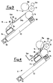
- Figure 3 is a schematic view of a portion of a re-reeling machine, with the device according to the invention in one first position; and
- Figure 4 is a schematic view of a portion of a re-reeling machine, with the device according to the invention in one second position.
-
- With reference to the above-mentioned figures, a device for introducing a winding core into a re-reeling machine is illustrated and is designated, as a whole, by the
reference number 11. - The
device 11 is mounted on a re-reeling machine, which is not shown in its entirety in that it is of itself known. - The re-reeling machine comprises a supporting assembly (not shown) from which a ribbon of paper that is processed in a perforating assembly (not illustrated) is unwound. The perforating assembly makes pre-determined tearing lines on the ribbon at equal distances apart.
- The ribbon thus processed is subsequently rewound into
rolls 12 by a windingassembly 14 of the re-reeling machine. The saidwinding assembly 14 comprises threerollers 16 that identify a space in which theroll 12 is temporarily housed during processing. - More in particular, two
winding rollers roller 16b, also referred to as "pressure roller" are present. - The machine comprises a frame provided with
cross members 20 on which twoguides 22 are fixed. On each of the guides 22 acarriage 24 can slide on which are fixed the two ends of abar 26. The latter is made of extremely rigid and light material, such as a composite material. - Fixed on the
bar 26 are supports 28 set at equal distances apart. Thesupports 28 are made using elongated plates at one end of each of which is set a pair ofrollers 30 supported by a pin. - The re-reeling machine comprises, as feeder for feeding
winding cores 32 to thedevice 11, a pair of chutes that guide acardboard core 32 from a gluer-feeder assembly (not shown), where thesaid cores 32 are deposited, as far as thewinding assembly 14. - In particular, each chute comprises a first
rectilinear portion 34a, which extends from the container and connects at right angles to asecond portion 34b, which is also rectilinear and ends so that it is tangential to one of therollers 16 of thewinding assembly 14. - The
bar 26 is connected to an actuator (not shown for reasons of simplicity), which drives it so that it moves along theguides 22. The actuator is in turn connected to an electronic control unit (not shown either) which controls it. - According to a variant of the present invention, the device is equipped with two motors, each of which is associated to an actuator, the said actuators being controlled synchronously by means of an electronic control.
- Operation of the
device 11 for introducing acore 32 into a re-reeling machine according to the invention is substantially as described in what follows. - The
cardboard core 32 slides along theportion 34a of the chutes and stops at theportion 34b (Figure 3). - Next, the
bar 26, driven by the actuator (or actuators) slides by means of thecarriages 24 on theguides 22, and when thewheels 30 arrive in contact with thecores 32, they push the latter, translating them along theportion 34b of the chutes, so as to supply them to the winding assembly 14 (Figure 4). - The impact between the winding
core 32 and the ribbon of paper, and in particular, the instant in which this impact occurs, contributes to causing tearing of the paper and the start of anew roll 12. - The electronic control unit determines the law according to which the
bar 26 and thecarriages 24 fixed to the latter move along theguides 22, and hence the law according to the which thecores 32 are introduced between therollers 16. - The speed of introduction and the instant of impact between the ribbon of paper and the
cores 32 is very important for the purposes of making a good-quality finishedroll 12. - The speed at which the
core 32 is introduced between therollers 16 is linked to the speed of the ribbon of paper. - The presence of the
wheels 30 proves very useful in that the said wheels, in addition to supporting thecore 32, enable its rotation at the instant of impact between therollers 16. - The system in question enables levels of performance in terms of precision and dynamics that up to now have not been achievable, considerably improving the versatility of the re-reeling machine and the quality of the finished product.
- In practice, it has been found that the device for introducing a winding core into a re-reeling machine according to the invention is particularly advantageous because it enables introduction of the cardboard cores of the rolls of paper in a very precise way, so obtaining finished products of very precise dimensions and high quality.
- The device for introducing a winding core into a re-reeling machine as devised may undergo numerous modifications and variations, all falling within the scope of the present invention. In addition, all the items may be replaced with others that are technically equivalent.
- In practice, the materials used, as well the dimensions, may be any whatsoever according to the technical requirements.
Claims (12)
- A device (11) for introducing a winding core (32) into a re-reeling machine, where said re-reeling machine comprises at least one winding assembly (14) for winding a ribbon of paper around said cores (32) and a feeder (34a, 34b) for feeding said cores (32) to said device (11), characterized in that it comprises at least one guide (22) connected to a frame (20) of said machine, on which at least one carriage (24) can slide, there being fixed to said carriage (24) at least one bar (26) which enables displacement of said cores (32) along at least part of said feeder (34a, 34b) to introduce them into said winding assembly (14).
- A device (11) according to Claim 1, characterized in that said bar (26) carries supports (28) for said cores (32).
- A device (11) according to Claim 1, characterized in that said supports (28) are set at equal distances apart.
- A device (11) according to Claim 1, characterized in that said supports (28) are made using elongated plates.
- A device (11) according to Claim 1, characterized in that at the ends of said supports at least one wheel (30) is present.
- A device (11) according to Claim 1, characterized in that said feeder (34a, 34b) comprises at least one pair of chutes that guide said core (32) from a container where said cores (32) are deposited up to said winding assembly (14).
- A device (11) according to Claim 6, characterized in that each chute comprises at least a first portion (34a) which extends from the container and is connected at right angles to a second portion (34b).
- A device (11) according to Claim 7, characterized in that said second portion (34b) ends at a point tangential to at least one roller (16) of said winding assembly (14).
- A device (11) according to Claim 1, characterized in that said bar (26) is connected to at least one actuator, which drives it so that it moves along said guides (22), said actuator being controlled by at least one electronic control unit.
- A device (11) according to Claim 1, characterized in that said bar (26) is made of a composite material.
- A device (11) according to Claim 1, characterized in that said winding assembly (14) comprises at least three rollers (16, 16a, 16b) which identify a space in which a roll (12) is temporarily housed during processing, where one of said rollers (16b) is a mobile roller.
- A device (11) according to Claim 9, characterized in that it comprises two motors, one for each actuator, controlled synchronously by means of an electronic control.
Applications Claiming Priority (2)
| Application Number | Priority Date | Filing Date | Title |
|---|---|---|---|
| ITMI992293 | 1999-11-03 | ||
| IT1999MI002293A IT1313815B1 (en) | 1999-11-03 | 1999-11-03 | INTRODUCTION DEVICE FOR A WINDING SOUL IN A REWINDER MACHINE |
Publications (1)
| Publication Number | Publication Date |
|---|---|
| EP1097890A1 true EP1097890A1 (en) | 2001-05-09 |
Family
ID=11383888
Family Applications (1)
| Application Number | Title | Priority Date | Filing Date |
|---|---|---|---|
| EP00203770A Withdrawn EP1097890A1 (en) | 1999-11-03 | 2000-10-30 | Device for introducing a winding core into a re-reeling machine |
Country Status (3)
| Country | Link |
|---|---|
| US (1) | US6517024B1 (en) |
| EP (1) | EP1097890A1 (en) |
| IT (1) | IT1313815B1 (en) |
Families Citing this family (3)
| Publication number | Priority date | Publication date | Assignee | Title |
|---|---|---|---|---|
| US10427903B2 (en) | 2016-03-04 | 2019-10-01 | The Procter & Gamble Company | Leading edge device for a surface winder |
| US10427902B2 (en) | 2016-03-04 | 2019-10-01 | The Procter & Gamble Company | Enhanced introductory portion for a surface winder |
| US10442649B2 (en) | 2016-03-04 | 2019-10-15 | The Procter & Gamble Company | Surface winder for producing logs of convolutely wound web materials |
Citations (3)
| Publication number | Priority date | Publication date | Assignee | Title |
|---|---|---|---|---|
| EP0387214A2 (en) * | 1989-03-09 | 1990-09-12 | FABIO PERINI S.p.A. | Rewinding machine for the formation of rolls of paper or the like |
| US5769352A (en) * | 1994-06-16 | 1998-06-23 | Fabio Perini S.P.A. | Web rewinding machine, adaptable to different core diameters |
| US5820064A (en) * | 1997-03-11 | 1998-10-13 | C.G. Bretting Manufacturing Company, Inc. | Winding control finger surface rewinder with core insert finger |
Family Cites Families (13)
| Publication number | Priority date | Publication date | Assignee | Title |
|---|---|---|---|---|
| US3239155A (en) * | 1962-02-16 | 1966-03-08 | Kureha Spinning Co Ltd | Lap winding and doffing apparatus |
| DE2007543A1 (en) * | 1970-02-19 | 1971-09-30 | Berstorff Gmbh Masch Hermann | Device for the continuous, fully automatic production of a foil roll |
| US3908923A (en) * | 1972-09-11 | 1975-09-30 | Leslie Salgo | Winding apparatus |
| US4299358A (en) * | 1979-01-22 | 1981-11-10 | Jagenberg-Werke A.G. | Method and apparatus for the automatic sidewise insertion of cores in winding machines |
| IT1165998B (en) * | 1979-09-21 | 1987-04-29 | Fabio Perini | CONTINUOUS WRAPPING DEVICE FOR PAPER TAPES AND MORE IN THE PRODUCTION OF TOILET PAPER AND SIMILAR MANUFACTURES |
| DE2948877C2 (en) * | 1979-12-05 | 1982-02-18 | Jagenberg-Werke AG, 4000 Düsseldorf | Double drum winding machine |
| US4422588A (en) * | 1981-09-28 | 1983-12-27 | The Black Clawson Company | Slitter-rewinder system |
| JPS59124644A (en) * | 1982-12-27 | 1984-07-18 | Ishikawajima Harima Heavy Ind Co Ltd | Method and apparatus for winding in paper machine |
| FI71109C (en) * | 1984-11-27 | 1986-11-24 | Waertsilae Oy Ab | FOERFARANDE OCH ANORDNING FOER ATT FAESTA BANANS AENDE VID EN HYLSA I EN RULLNINGSMASKIN |
| US4909452A (en) * | 1988-02-29 | 1990-03-20 | Paper Converting Machine Company | Surface winder and method |
| DE3811871A1 (en) * | 1988-04-09 | 1989-10-26 | Jagenberg Ag | METHOD AND DEVICE FOR WINDING MATERIALS, IN PARTICULAR PAPER OR CARDBOARD |
| DE4334029C2 (en) * | 1993-10-06 | 1998-01-22 | Jagenberg Papiertech Gmbh | Carrier roll winding machine |
| CZ283034B6 (en) * | 1994-08-24 | 1997-12-17 | Maschinenfabrik Rieter Ag | Process and apparatus for supplying winding devices of textile machine with empty tubes |
-
1999
- 1999-11-03 IT IT1999MI002293A patent/IT1313815B1/en active
-
2000
- 2000-10-30 US US09/702,079 patent/US6517024B1/en not_active Expired - Fee Related
- 2000-10-30 EP EP00203770A patent/EP1097890A1/en not_active Withdrawn
Patent Citations (3)
| Publication number | Priority date | Publication date | Assignee | Title |
|---|---|---|---|---|
| EP0387214A2 (en) * | 1989-03-09 | 1990-09-12 | FABIO PERINI S.p.A. | Rewinding machine for the formation of rolls of paper or the like |
| US5769352A (en) * | 1994-06-16 | 1998-06-23 | Fabio Perini S.P.A. | Web rewinding machine, adaptable to different core diameters |
| US5820064A (en) * | 1997-03-11 | 1998-10-13 | C.G. Bretting Manufacturing Company, Inc. | Winding control finger surface rewinder with core insert finger |
Also Published As
| Publication number | Publication date |
|---|---|
| ITMI992293A0 (en) | 1999-11-03 |
| IT1313815B1 (en) | 2002-09-23 |
| ITMI992293A1 (en) | 2001-05-03 |
| US6517024B1 (en) | 2003-02-11 |
Similar Documents
| Publication | Publication Date | Title |
|---|---|---|
| AU2011310449B2 (en) | Rewinding machine and method for the production of rolls of web material | |
| KR100202227B1 (en) | Rewinder for producing log of web material, selectively with or without a winding core | |
| EP1630115B1 (en) | Rewinding machine to rewind web material on a core for rolls and corresponding method of winding | |
| US20130008995A1 (en) | Machine and method for winding reels of web material | |
| EP2655227B1 (en) | Rewinding machine and winding method | |
| EP0439480B1 (en) | Re-reeling machine working at constant speed | |
| ITFI20090274A1 (en) | "CUTTING MACHINE FOR CUTTING ROLLS OF RIBBED MATERIAL" | |
| ITFI980131A1 (en) | WINDING OR REWINDING MACHINE FOR THE FORMATION OF ROLLS OF BIG DIAMETER TAPE MATERIAL | |
| EP0498039B1 (en) | Improvements to re-reeling machines for sheet material | |
| US6948678B2 (en) | Rewinding machine with auxiliary cylinders and respective winding method | |
| US5273222A (en) | Multiple-station winding machine for the winding of webs of foil or the like | |
| US4848059A (en) | Apparatus for packing a cylindrical stack of disk-like workpieces | |
| US5535573A (en) | Apparatus (blank unit) for feeding blanks to an article which is to be wrapped | |
| EP1375402B1 (en) | Rewinding machine with means for axially pulling the winding mandrel | |
| US6517024B1 (en) | Device for introducing a winding core into a re-reeling machine | |
| ITFI980058A1 (en) | DEVICE FOR THE MUTUAL SEPARATION OF A PLURALITY OF ARTICLES, ONE IN CONTACT WITH THE OTHER. | |
| US4934620A (en) | Apparatus for winding coaxial insulation onto a winding core | |
| RU2237004C1 (en) | Rewinding machine and method of winding thin-sheet material onto roll quill | |
| EP3502022B1 (en) | Rewinding machine and relative method for rewinding and forming a roll of paper | |
| KR100431632B1 (en) | Device for the automatic supplying of cardboard |
Legal Events
| Date | Code | Title | Description |
|---|---|---|---|
| PUAI | Public reference made under article 153(3) epc to a published international application that has entered the european phase |
Free format text: ORIGINAL CODE: 0009012 |
|
| AK | Designated contracting states |
Kind code of ref document: A1 Designated state(s): AT BE CH CY DE DK ES FI FR GB GR IE IT LI LU MC NL PT SE |
|
| AX | Request for extension of the european patent |
Free format text: AL;LT;LV;MK;RO;SI |
|
| AKX | Designation fees paid | ||
| REG | Reference to a national code |
Ref country code: DE Ref legal event code: 8566 |
|
| STAA | Information on the status of an ep patent application or granted ep patent |
Free format text: STATUS: THE APPLICATION IS DEEMED TO BE WITHDRAWN |
|
| 18D | Application deemed to be withdrawn |
Effective date: 20011112 |