EP1097357B1 - Ameliorations apportees a des detecteurs de parametres de fonctionnement de conduit et methodes d'exploitation - Google Patents
Ameliorations apportees a des detecteurs de parametres de fonctionnement de conduit et methodes d'exploitation Download PDFInfo
- Publication number
- EP1097357B1 EP1097357B1 EP99930621A EP99930621A EP1097357B1 EP 1097357 B1 EP1097357 B1 EP 1097357B1 EP 99930621 A EP99930621 A EP 99930621A EP 99930621 A EP99930621 A EP 99930621A EP 1097357 B1 EP1097357 B1 EP 1097357B1
- Authority
- EP
- European Patent Office
- Prior art keywords
- complex
- eigenvector
- circuitry
- motion
- transformation
- Prior art date
- Legal status (The legal status is an assumption and is not a legal conclusion. Google has not performed a legal analysis and makes no representation as to the accuracy of the status listed.)
- Expired - Lifetime
Links
Images


Classifications
-
- G—PHYSICS
- G01—MEASURING; TESTING
- G01F—MEASURING VOLUME, VOLUME FLOW, MASS FLOW OR LIQUID LEVEL; METERING BY VOLUME
- G01F1/00—Measuring the volume flow or mass flow of fluid or fluent solid material wherein the fluid passes through a meter in a continuous flow
- G01F1/76—Devices for measuring mass flow of a fluid or a fluent solid material
- G01F1/78—Direct mass flowmeters
- G01F1/80—Direct mass flowmeters operating by measuring pressure, force, momentum, or frequency of a fluid flow to which a rotational movement has been imparted
- G01F1/84—Coriolis or gyroscopic mass flowmeters
- G01F1/8409—Coriolis or gyroscopic mass flowmeters constructional details
- G01F1/8413—Coriolis or gyroscopic mass flowmeters constructional details means for influencing the flowmeter's motional or vibrational behaviour, e.g., conduit support or fixing means, or conduit attachments
-
- G—PHYSICS
- G01—MEASURING; TESTING
- G01F—MEASURING VOLUME, VOLUME FLOW, MASS FLOW OR LIQUID LEVEL; METERING BY VOLUME
- G01F1/00—Measuring the volume flow or mass flow of fluid or fluent solid material wherein the fluid passes through a meter in a continuous flow
- G01F1/76—Devices for measuring mass flow of a fluid or a fluent solid material
- G01F1/78—Direct mass flowmeters
- G01F1/80—Direct mass flowmeters operating by measuring pressure, force, momentum, or frequency of a fluid flow to which a rotational movement has been imparted
- G01F1/84—Coriolis or gyroscopic mass flowmeters
- G01F1/8409—Coriolis or gyroscopic mass flowmeters constructional details
- G01F1/8436—Coriolis or gyroscopic mass flowmeters constructional details signal processing
-
- G—PHYSICS
- G01—MEASURING; TESTING
- G01F—MEASURING VOLUME, VOLUME FLOW, MASS FLOW OR LIQUID LEVEL; METERING BY VOLUME
- G01F1/00—Measuring the volume flow or mass flow of fluid or fluent solid material wherein the fluid passes through a meter in a continuous flow
- G01F1/76—Devices for measuring mass flow of a fluid or a fluent solid material
- G01F1/78—Direct mass flowmeters
- G01F1/80—Direct mass flowmeters operating by measuring pressure, force, momentum, or frequency of a fluid flow to which a rotational movement has been imparted
- G01F1/84—Coriolis or gyroscopic mass flowmeters
- G01F1/845—Coriolis or gyroscopic mass flowmeters arrangements of measuring means, e.g., of measuring conduits
- G01F1/8468—Coriolis or gyroscopic mass flowmeters arrangements of measuring means, e.g., of measuring conduits vibrating measuring conduits
- G01F1/8472—Coriolis or gyroscopic mass flowmeters arrangements of measuring means, e.g., of measuring conduits vibrating measuring conduits having curved measuring conduits, i.e. whereby the measuring conduits' curved center line lies within a plane
- G01F1/8477—Coriolis or gyroscopic mass flowmeters arrangements of measuring means, e.g., of measuring conduits vibrating measuring conduits having curved measuring conduits, i.e. whereby the measuring conduits' curved center line lies within a plane with multiple measuring conduits
Definitions
- This invention pertains to process parameter sensors and related operating methods and program products, and more particularly, to vibrating conduit process parameter sensors and related operating methods and computer program products.
- Coriolis effect mass flowmeters are commonly used to measure mass flow and other information for materials flowing through a conduit.
- Exemplary Coriolis flowmeters are disclosed in U.S. Pat. Nos. 4,109,524 of August 29, 1978 , 4,491,025 of January 1, 1985 , and Re. 31,450 of February 11, 1982 , all to J. E. Smith et al.
- These flowmeters typically include one or more conduits having a straight or a curved configuration.
- Each conduit may be viewed as having a set of vibration modes, including, for example, simple bending, torsional, radial and coupled modes.
- each conduit is driven to oscillate at resonance in one of its natural modes as a material flows through the conduit.
- the vibration modes of the vibrating, material-filled system are affected by the combined mass and stiffness characteristics of the conduits and the characteristics of the material flowing within the conduits.
- a typical component of a Coriolis flowmeter is the drive or excitation system.
- the drive system operates to apply a periodic physical force to the conduit that causes the conduit to oscillate.
- the drive system typically includes at least one actuator mounted to the conduit(s) of the flowmeter.
- the actuator typically contains one of many well known electromechanical devices, such as a voice coil device having a magnet mounted to a first conduit and a wire coil mounted to a second conduit, in an opposing relationship to the magnet.
- a drive circuit continuously applies a periodic, e.g., a sinusoidal or square wave, drive signal to the actuator coil.
- the periodic drive signal causes the actuator to drive the two conduits in an opposing periodic pattern that is thereafter maintained.
- Coriolis flowmeters To measure mass flow rate, conventional Coriolis flowmeters typically measure phase at two transducers located near respective ends of the conduit, symmetrically placed with respect to a centrally positioned driver.
- manufacturing-induced asymmetries in transducer placement as well as other structural asymmetries and nonlinearities in the conduit structure may cause measurement inaccuracies.
- the method is performed by meter electronics.
- the meter electronics receive a plurality of motion signals from the plurality of motion transducers.
- the meter electronics determine a complex modal transformation of a calibrated complex eigenvector from the plurality of motion signals.
- the calibrated complex eigenvector is a known rotation of a complex eigenvector associated with a drive mode at a known mass flow rate of material.
- the complex modal transformation is a matrix which transforms the calibrated complex eigenvector to a rotation of the complex eigenvector associated with the drive mode for the unknown mass flow rate of the material.
- the meter electronics estimates a process parameter for the material processing system from the complex modal transformation.
- the step of determining the complex modal transformation includes generating a plurality of complex measured values from the received plurality of motion signals, a respective one of the plurality of complex measured values corresponding to a respective one of the plurality of locations and estimating a complex modal transformation relating the generated plurality of complex measured values to the calibrated complex eigenvector.
- the step of determining the complex modal transformation includes constructing a complex vector from the generated plurality of complex measured values and determining a scaled rotation relating the complex vector to the complex eigenvector.
- the step of determining the complex modal transformation comprises the step of determining a scaling factor relating the plurality of complex measured values to the calibrated complex eigenvector.
- the step of determining the complex modal transformation comprises the step of determining a transformation which best fits the plurality of complex measured values to the calibrated complex eigenvector, and the step of estimating mass flow comprises the step of estimating mass flow from the known mass flow associated with the calibrated complex eigenvector and the complex transformation.
- the step of providing the calibrated complex eigenvector comprises the step of providing a plurality of complex calibrated values representing motion of the conduit at the known mass flow and the step of determining the transformation comprises the step of performing a linear regression to determine a transformation relating the plurality of complex calibrated values to the plurality of complex measured values.
- the step of determining the transformation comprises the step of determining a transformation which optimally fits the plurality of complex measured values to the calibrated complex eigenvector according to a least squares criteria.
- the step of receiving comprises the step of receiving a plurality of motion signals representing motion at more than two physically separate locations and the step of determining the complex modal transformation comprises the step of estimating a complex modal transformation relating the plurality of motion signals representing motion at the more than two physically separate locations to the complex eigenvector.
- the step of receiving comprises the step of receiving a plurality of motion signals representing motion at more than two physically separate locations
- the step of generating the plurality of complex measured values comprises the step of generating more than two complex measured values
- the step of estimating the complex modal transformation comprises the step of estimating a complex modal transformation relating the generated at least two complex measured values to the complex eigenvector.
- the step of generating a plurality of complex measured values comprises the step of generating a measured phase value corresponding to a location of the plurality of locations.
- the step of generating a plurality of complex measured values comprises the step of generating a measured amplitude value corresponding to a location of the plurality of locations.
- the meter electronics receive a plurality of motion signals from the plurality of motion transducers, the plurality of motion signals indicating motion at the plurality of locations at the known mass flow, determine a complex eigenvector from the received plurality of motion signals, and store a representation of the complex eigenvector.
- the step of providing a complex eigenvector comprises the step of storing a representation of the complex eigenvector.
- said complex modal transformation determining circuitry (35) comprises circuitry (38) configured to estimate said complex modal transformation relating the received plurality of motion signals to a complex eigenvector representing motion of said conduit at a known mass flow; and wherein said process parameter estimator circuitry (40) comprises circuitry configured to estimate mass flow through said conduit (103A-103B) from the known mass flow and said complex modal transformation (35).
- said complex modal transformation determining circuitry (35) comprises:
- circuitry (330) configured to estimate said complex modal transformation comprises circuitry configured to determine a scaling factor relating the plurality of complex measured values to the complex eigenvector; and wherein said circuitry (340) configured to estimate mass flow comprises means for estimating mass flow from the known mass flow and the computed scaling factor.
- circuitry (330) configured to estimate a complex modal transformation comprises circuitry (334) configured to determine a transformation which best fits the plurality of complex measured values to the complex eigenvector; and wherein said circuitry (340) configured to estimate said mass flow comprises circuitry configured to estimate mass flow from the known mass flow according to the determined transformation.
- said circuitry (334) configured to determine said transformation comprises circuitry configured to perform a linear regression to determine a transformation which best fits the plurality of complex measured values to the complex eigenvector. More preferably the apparatus further comprises circuitry configured to provide a plurality of complex calibrated values representing motion of the conduit at the known mass flow, and wherein said circuitry (334) configured to determine said transformation comprises circuitry configured to perform a linear regression to determine a transformation relating the plurality of complex calibrated values to the plurality of complex measured values.
- circuitry (334) configured to determine said transformation comprises circuitry configured to determine a transformation which optimally fits the plurality of complex measured values to the complex eigenvector according to a least squares criteria.
- the plurality of motion signals represent motion at a more than two physically separate locations on the conduit
- said complex modal transformation estimator circuitry is configured to receive the plurality of motion signals representing motion at the more than two physically separate locations and operative to estimate a complex modal transformation relating the received plurality of motion signals representing motion at the more than two physically separate locations to the calibrated complex eigenvector.
- the plurality of motion signals represent motion at a more than two physically separate locations on the conduit, and:
- the circuitry configured to generate a plurality of complex measured values comprises circuitry configured to generate a measured phase value corresponding to a location of said plurality of locations.
- the circuitry configured to generate a plurality of complex measured values comprises circuitry configured to generate a measured amplitude value corresponding to a location of said plurality of locations.
- the apparatus further comprises circuitry (313) configured to store a representation of the complex eigenvector.
- a process parameter of a material processing system typically mass flow rate
- a material e.g., a fluid
- a vibrating conduit configured to contain a material which passes through the vibrating conduit as part of the material processing system.
- the present invention is also applicable to vibrating conduit process parameter sensors other than in-line sensors.
- the present invention is applicable to sampling-type vibrating-tube densitometers which include a conduit configured to contain a sample of a material extracted from a material processing system.
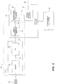
- FIG. 1 shows an exemplary embodiment of a process parameter sensor 5 according to the present invention.
- the process parameter sensor 5 includes a conduit assembly 10 .
- the conduit assembly 10 includes an inlet flange 101 , an outlet flange 101' , a manifold 102 and first and second conduits 103A , 103B .
- Brace bars 106 , 106' connect the conduits 103A , 103B .
- Connected to the conduits 103A , 103B is an actuator 104 that is operative to vibrate the conduits 103A , 103B responsive to a driver 20 .
- First and second motion transducers 105 , 105' are operative to produce motion signals representing motion at spatially separate locations on the conduits 103A , 104B .
- the motion transducers 105 , 105 ' may include a variety of devices, such as coil-type velocity transducers, optical or ultrasonic motion sensors, accelerometers, inertial rate sensors and the like. Leads 100 are connected to the actuator 104 and the motion transducers 105 , 105' .
- conduit assembly 10 When the conduit assembly 10 is inserted into a material processing system 1, material flowing in the material processing system 1 enters the conduit assembly 10 through the inlet flange 101 . The material then flows through the manifold 102 , where it is directed into the flow tubes 103A, 103B . After leaving the flow tubes 103A , 103B , the material flows back into the manifold 102 and exits the meter assembly 10 through the outlet flange 101' . As the material flows through the conduits 103A , 103B , it gives rise to Coriolis forces that perturb the conduits 103A , 103B .
- the conduits 103A , 103B are typically driven by the actuator 104 in opposite directions about their respective bending axes W-W and W'-W', inducing what is commonly referred to as a first out of phase bending mode in the conduit assembly 10.
- the actuator 104 may comprise any one of many well-known devices, such as a linear actuator including a magnet mounted to the first conduit 103A and an opposing coil mounted to the second flow tube 103B.
- An alternating current induced by a drive signal provided by a driver 20 via a drive lead 110 passes through the coil, generating mechanical force that vibrates the conduits 103A , 103B.
- vibration of the conduits 103A, 103B according to the present invention may be achieved by other techniques, such as by an excitation generated external to the conduit assembly 10 and conveyed to the conduit assembly 10 , via one of the flanges 101 , 101' .
- Steady-state motion of a vibrating process parameter sensor conduit at zero mass flow can be described as a real normal eigenvector associated with the fundamental mode excited by the driver.
- this mode typically is a first out-of-phase bending mode in which the two conduits 103A , 103B bend about the axes W-W, W'-W' .
- ⁇ x ⁇ t ⁇ ⁇ ⁇ ⁇ ⁇ d cos ⁇ d ⁇ t
- ⁇ d represents a real, normal eigenvector associated with the drive mode
- ⁇ d is a natural frequency associated with the drive mode.
- the scalar ⁇ scales the eigenvector ⁇ d to match the amplitude of the vibration.
- the motion of any point on the conduit can be directly determined.
- a more complete representation of operation of a vibrating conduit process parameter sensor may be provided by viewing the process parameter sensor as a system operating in a state of forced response.
- the forced response may be modeled as a superposition of a plurality of real normal modal responses ⁇ .
- ⁇ x ⁇ t ⁇ ⁇
- x ⁇ ⁇
- ⁇ ⁇ - 1 x
- x H F
- ⁇ ⁇ - 1 H F
- ⁇ ⁇ ⁇ is a modal response vector
- ⁇ F ⁇ is a forcing function vector
- [H] is a frequency response function (FRF) matrix
- [ ⁇ ] -1 is an inverse of a mode shape matrix [ ⁇ ].
- each term of the vector ⁇ x ⁇ has a phase associated therewith.
- the force vector ⁇ F ⁇ and the system characteristics embodied in the FRF matrix [H] are known, measuring the phase at any one point on the conduit generally will yield the correct phase at any other point on the conduit.
- the present invention arises from the realization that flowing material in a conduit may be represented as Coriolis forces which introduce complexity in a modal model of a conduit assembly.
- the Coriolis forces can be modeled using additional terms in the matrix associated with the velocity term in the linear differential equations describing the motion of the process parameter sensor conduit.
- the eigenvectors i.e., the mode shapes, become complex.
- Motion of a conduit with fluid flowing through the conduit can be modeled as a scaled complex eigenvector.
- a complex eigenvector has two independent components at each degree of freedom. These components may include real and imaginary components or, alternatively, magnitude and phase components. According to this model, the motion of the conduit can be described by a free response, i.e., the drive force can be neglected in the description of the motion.
- ⁇ x ⁇ t ⁇ ⁇
- d ⁇ the magnitude of the complex eigenvector
- the drive circuit that drives the transducer to a given amplitude As ang ( ⁇ d ), the complexity of the eigenvector, is unknown, information about motion at two locations can be used to determine the Coriolis forces.
- the complex modal response ⁇ ⁇ ⁇ involves the system characteristics, represented by the FRF matrix [H], and the applied force vector ⁇ F ⁇ . It may be assumed that the applied force vector ⁇ F ⁇ is known. However, the system characteristics, embodied in the FRF matrix [H], are a function of the mass flow rate and thus are unknown. Additional information, e.g., phase at a point other than the driver, allows determination of the mass flow rate.
- Complex modal measurement techniques as applied according to the present invention can provide greater flexibility in measuring process parameters such as mass flow than conventional methods. For example, if amplitude is precisely controlled at one location, e.g., the driver location, the amplitude or phase of another location can provide sufficient information for a mass flow calculation. Alternatively, amplitude measured simultaneously at two separate locations, each amplitude measurement being normalized to a maximum amplitude at the location, can provide sufficient information for a mass flow measurement.
- the complexity of a mode may be viewed as a rotation of an eigenvector in the complex plane. Knowing the imaginary part of the eigenvector at any two locations can provide information on the mode shape complexity.
- the imaginary rotation is related to the mass flow.
- a meter is calibrated such that the rotation, i.e., a complex eigenvector, is known at a known mass flow.
- An unknown mass flow e.g., an unknown mass flow rate, totalized mass flow or the like, may be determined by determining a corresponding complex vector and assuming that this vector corresponds to complex modal transformation of the calibrated complex eigenvector.
- the transformation may be estimated from the calibrated complex eigenvector and the measurement vector using, for example, a curve fitting technique. The estimated transformation may then be used to estimate the unknown mass flow from the known mass flow.
- the calibrated complex eigenvector may be identified in a number of ways.
- a sensor may be calibrated offline as part of a manufacturing process, with the calibrated complex eigenvector being stored in a programmable read-only memory (PROM) or other storage device in the process parameter sensor's electronics.
- the calibrated complex eigenvector may be stored in a number of ways including, for example, by storing a plurality of values of the complex eigenvector or by storing a representation or approximation thereof.
- a process parameter sensor may also be calibrated in situ by passing material through the process parameter sensor at a known flow rate and determining the calibrated complex eigenvector by performing a complex modal analysis under control of a microprocessor or similar computing device.
- a number of computational techniques may be utilized to estimate the complex eigenvectors for a given flow rate and for computing the transformation relating complex eigenvectors representing different flow rates. These may include various curve-fitting techniques, such as regression techniques.
- a generalized linear regression technique is used to determine mass flow.
- ⁇ Y e ⁇ could include, for example, phase measurements at the two transducer locations on the process parameter sensor conduit.
- Equation (9) is in a form that allows computation of ⁇ c ⁇ .
- this could be achieved by premultiplying both sides of Equation (9) by [Z] -1 , as [Z] has an equal number of rows and columns.
- [Z] could represent an overdetermined system, i.e., [Z] could have more rows and columns. This could arise if measurements are made at more than two locations on the conduit, i.e., if ⁇ X ⁇ has more than two elements.
- [Z] T [Z] is a square matrix, which for a physically well-posed problem has an inverse.
- Premultiplying both sides of Equation (8) by the inverse of [Z] T [Z] and solving for ⁇ c ⁇ : c Z T Z - 1 ⁇ Z T Y e .
- the result ⁇ c ⁇ represents a best fit of the vector ⁇ X ⁇ to the complex eigenvector ⁇ Y e ⁇ according to a least squares criteria.
- the first element of ⁇ c ⁇ the slope a , represents a scaling factor for a scaled rotation of ⁇ X ⁇ to fit ⁇ Y e ⁇ .
- an embodiment of a process parameter sensor 5 includes a complex modal transformation estimator 30 and a process parameter estimator 40 .
- Leads 100 connect the conduit assembly 10 to the driver 20 and the complex modal transformation estimator 30 .
- the complex modal transformation estimator 30 receives first and second motion signals representing motion of the conduits 103A , 103B , e.g., signals representing displacement, velocity or acceleration as a material flows through the conduit assembly 10 , from the first and second motion transducers 105, 105' on first and second leads 111 , 111' , respectively.
- the complex transformation estimator 30 processes the received motion signals to estimate a complex modal transformation 35 relating the motion signals to a complex eigenvector representing motion of the conduits 103A , 103B at a known mass flow.
- the process parameter estimator 40 generates an estimate 45 of the unknown mass flow, e.g., an estimated mass flow rate, from the known mass flow according to the estimated complex modal transformation 35 .
- FIG. 2 illustrates an exemplary embodiment of the complex modal transformation estimator 30 and the process parameter estimator 40.
- the complex modal transformation estimator 30 includes a sampler 32 , for example, a sample-and-hold or similar circuit, and an analog-to-digital converter (A/D) 34 .
- the sampler 32 and the A/D 34 provide means 31 for receiving motion transducer motion signals 25 produced by the first and second motion transducers 105 , 105' , sampling the motion signals 25 and producing samples 33 therefrom which are converted to digital signal values 37 by the analog-to-digital converter (A/D) 34 .
- A/D analog-to-digital converter
- the receiving means 31 illustrated in FIG. 2 may be implemented in a number of ways, including additional presampling anti-alias filtering, postsampling filtering and the like. It will also be understood that, in general, the receiving means 31 illustrated in FIG. 2 may be implemented using special purpose hardware, firmware or software running on special or general-purpose data processing devices, or combinations thereof. Portions of the complex modal transformation estimator 30 may be embodied in a computer 50 , e.g., a microprocessor, microcontroller, digital signal processor (DSP) or the like.
- DSP digital signal processor
- the computer 50 may comprise a pipelined DSP especially suited for linear algebraic computations, such as a DSP of the TMS320C4X family of DSPs sold by Texas Instruments, Inc. configured with appropriate program code, e.g., software and/or firmware and data stored, for example, in a storage medium 60 such as a random access memory (RAM), programmable read-only memory (EPROM), magnetic disk or the like, the computer 50 provides means 36 for generating complex measured values 39 from the digital signal values 37, the complex measured values representing motion of the conduits 103A , 103B .
- a storage medium 60 such as a random access memory (RAM), programmable read-only memory (EPROM), magnetic disk or the like
- the computer 50 and associated program code also provide means 38 for estimating a complex modal transformation 35 from the complex measured values 39 , the estimated complex modal transformation relating the complex measured values 39 to a complex eigenvector representing motion of the conduits 103A , 103B at a known mass flow.
- the process parameter estimator 40 may also be embodied in the computer 50 . Embodied, for example, as software or firmware running on the computer 50 , the process parameter estimator 40 computes an estimate 45 of the unknown mass flow from the known mass flow according to the computed estimated complex modal transformation 35 produced by the complex modal transformation estimating means 38 . Detailed discussion of apparatus, methods and program products for performing these operations are discussed in greater detail below with reference to the flowchart illustrations of FIGs. 3-5 .
- FIGs. 1-2 illustrate exemplary embodiments, and that a variety of other apparatus may be used with the present invention.
- a variety of different conduit configurations other than that illustrated in FIG. 1 could be utilized, including straight and curved conduit configurations, as well as configurations employing a single conduit or multiple conduits.
- the driver 20 , the complex modal transformation estimator 30 and the process parameter estimator 40 may be implemented in an integrated fashion, e.g., in an electronics package attached to the conduit assembly 10 , or in a distributed fashion using components linked by appropriate communications media. Accordingly, a process parameter sensor as described herein need not be limited to a single package.
- the complex modal estimator 30 and/or the process parameter estimator 40 may also be implemented as hardware and/or software modules designed to interface with an existing conduit assembly 10 , including existing transducers 105A , 105B and associated wiring, thus providing an apparatus for retrofitting existing parameter sensor to incorporate complex modal measurement techniques.
- a driver 20 could also be integrated with such a module.
- a "kit” could be provided which includes a complex modal transformation estimator 30, a process parameter estimator 40 and motion transducers designed to mount on an existing conduit structure.
- the complex modal transformation estimator 30 and the process parameter estimator 40 as described herein use digital computation techniques implemented on digital computing apparatus such as a DSP to perform estimation operations according to aspects of the present invention, those skilled in the art will appreciate that the complex modal transformation estimator 30 and/or the process parameter estimator 40 may include non-digital components, such as analog computing circuits, which perform all or some of these estimation operations.
- FIGs. 3-5 are flowchart illustrations of methods, apparatus (systems) and program products according to the invention. Blocks or combinations of blocks in the flowchart illustrations can be implemented using computer readable program code, e.g., program instructions and/or data operated on in a computer or data processor such as the computer 50 illustrated in FIG. 2 .
- computer readable program code may include but is not limited to such things as operating system commands (e.g., object code), high-level language instructions, and the like, as well as data which may be read, accessed or otherwise utilized in conjunction with such program instructions.
- the program code may be loaded onto a computer or similar data processing apparatus including, but not limited to, a microprocessor, a microcontroller, a digital signal processor (DSP) or the like.
- the combination of the program code and computer may provide an apparatus that is operative to implement a function or functions specified in a block or blocks of the flowchart illustrations.
- the program code may be loaded onto a computer or data processing device such that the program code and computer provide means for performing the function or functions specified in a flowchart block or blocks.
- the program code may also be stored in a computer-readable storage medium such as a magnetic disk or tape, a bubble memory, a programmable memory device such as an electrically-erasable programmable read-only memory (EEPROM), or the like.
- the stored program code may direct a computer accessing the storage medium to function such that the program code stored in the storage medium forms an article of manufacture including program code means for implementing the function or functions specified in a flowchart block or blocks.
- the program code may also be loaded onto a computer to cause a series of operational steps to be performed, thereby implementing a process such that the program code, in conjunction with the computer, provides steps for implementing the functions specified in a flowchart block or blocks. Accordingly, blocks of the flowchart illustrations support apparatus operative to perform the specified functions, combinations of means for performing the specified functions, combinations of steps that perform the specified functions and computer readable program code means embodied in a computer-readable storage medium for performing the specified functions.
- each block of the flowchart illustrations, and combinations of blocks in the flowchart illustrations can be implemented by special purpose hardware, software or firmware executing on a general purpose computer, or combinations thereof.
- functions of the blocks of the flowchart illustrations may be implemented by an application specific integrated circuit (ASIC), programmable gate array or similar special purpose device, or by program instructions and data loaded on and executed by a microprocessor, microcontroller, DSP or other general-purpose computing device.
- ASIC application specific integrated circuit
- DSP digital signal processor
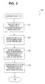
- FIG. 3 illustrates exemplary operations 300 for determining mass flow in a vibrating conduit type process parameter sensor.
- a complex eigenvector is provided (Block 310 ), the complex eigenvector representing motion of the process parameter sensor conduit at a known mass flow.
- a plurality of motion signals is received from a plurality of motion transducers (Block 320 ), the motion signals representing motion of the conduit at the plurality of locations as material flows through the conduit.
- a complex modal transformation relating the motion signals to the complex eigenvector is estimated (Block 330 ), for example, using the linear regression technique discussed above. Mass flow is then estimated from the known mass flow and the estimated complex modal transformation (Block 340 ).
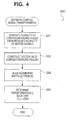
- FIG. 4 illustrates exemplary operations 330 for estimating a complex modal transformation relating the plurality of motion signals from the motion transducers to the complex eigenvector ⁇ Y e ⁇ , in particular, estimation operations incorporating a linear regression.
- a plurality of complex measured values is generated from the received plurality of motion signals (Block 331 ).
- a vector ⁇ X ⁇ is constructed from the plurality of complex measured values (Block 332).
- An augmented matrix [Z] is constructed from the vector ⁇ X ⁇ (Block 333 ).
- FIG. 5 illustrates exemplary operations 310 for providing a complex eigenvector representing motion of a process parameter sensor conduit at a known mass flow.
- a plurality of motion signals is received from a plurality of transducers positioned at a plurality of locations on the conduit (Block 311), the plurality of motion signals representing motion of the process parameter sensor conduit at a known mass flow.
- a complex eigenvector representing motion of the conduit at the known mass flow rate is then determined from the,plurality of complex calibrated values (Block 312 ).
- a representation of the complex eigenvector is then stored in the process parameter sensor (Block 314 ), for example, in the storage medium 60 illustrated in FIG. 2 .
Landscapes
- Physics & Mathematics (AREA)
- Fluid Mechanics (AREA)
- General Physics & Mathematics (AREA)
- Engineering & Computer Science (AREA)
- Signal Processing (AREA)
- Measuring Volume Flow (AREA)
- Measurement Of Mechanical Vibrations Or Ultrasonic Waves (AREA)
Abstract
Claims (29)
- Méthode (300) exécutée par un capteur de paramètres (5) pour déterminer un paramètre de procédé (45) à partir d'une pluralité de signaux de mouvement générés à partir d'une pluralité de transducteurs de mouvement (105A-105B) fixés à une conduite (103A-103B) qu'un dispositif d'entraînement (104) fait osciller au fur et à mesure qu'un matériau s'écoule dedans à un débit massique inconnu, la méthode comprenant l'étape qui consiste à :recevoir (320) une pluralité de signaux de mouvement à partir de ladite pluralité de transducteurs de mouvement (105-105'), dans laquelle la pluralité de signaux de mouvement représente un mouvement à une pluralité d'emplacements sur la conduite quand ladite conduite oscille ;la méthode étant caractérisée en ce qu'elle comprend en outre les étapes qui consistent à :déterminer une transformation modale complexe d'un vecteur propre complexe calibré à partir de ladite pluralité de signaux de mouvement dans laquelle ledit vecteur propre complexe calibré est une rotation connue d'un vecteur propre complexe associée à un mode d'entraînement à un débit massique connu de matériau et ladite transformation modale complexe est une matrice qui transforme ledit vecteur propre complexe calibré en une rotation dudit vecteur propre complexe associée audit mode d'entraînement pour ledit débit massique inconnu dudit matériau ; etestimer (340) un paramètre de procédé (45) pour le système de transformation d'un matériau à partir de ladite transformation modale complexe.
- Méthode (300) selon la revendication 1, dans laquelle ladite étape (330) de détermination de la transformation modale complexe comprend les étapes qui consistent à :générer (331) une pluralité de valeurs mesurées complexes à partir de la pluralité de signaux de mouvement qui a été reçue, l'une, respective, de la pluralité de valeurs mesurées complexes correspondant à l'une, respective, de la pluralité d'emplacements ; etestimer (332) une transformation modale complexe faisant correspondre la pluralité de valeurs mesurées complexes qui a été générée audit vecteur propre complexe calibré.
- Méthode (300) selon la revendication 2, dans laquelle ladite étape (330) de détermination de ladite transformation modale complexe comprend les étapes qui consistent à :construire (332) un vecteur complexe à partir de la pluralité de valeurs mesurées complexes qui a été générée ; etdéterminer (334) une rotation mise à l'échelle faisant correspondre le vecteur complexe au vecteur propre complexe.
- Méthode (300) selon la revendication 2, dans laquelle ladite étape (33C) de détermination de ladite transformation modale complexe comprend l'étape qui consiste à déterminer (334) un facteur de mise à l'échelle faisant correspondre la pluralité de valeurs mesurées complexes audit vecteur propre complexe calibré.
- Méthode (300) selon la revendication 2,
dans laquelle ladite étape (330) de détermination de ladite transformation modale complexe comprend l'étape qui consiste à déterminer (333) une transformation qui fait le mieux correspondre la pluralité de valeurs mesurées complexes audit vecteur propre complexe calibré ; et
dans laquelle ladite étape (340) d'estimation du débit massique comprend l'étape qui consiste à estimer un débit massique à partir du débit massique connu associé audit vecteur propre complexe calibré et à ladite transformation complexe. - Méthode (300) selon la revendication 5, dans laquelle ladite étape (333) de détermination de ladite transformation comprend l'étape qui consiste à exécuter une régression linéaire pour déterminer une transformation qui fait le mieux correspondre la pluralité de valeurs mesurées complexes au vecteur propre complexe.
- Méthode selon la revendication 5,
dans laquelle ladite étape (310) de fourniture dudit vecteur propre complexe calibré comprend l'étape qui consiste à fournir (312) une pluralité de valeurs calibrées complexes représentant un mouvement de la conduite au débit massique connu ; et
dans laquelle ladite étape (334) de détermination de ladite transformation comprend l'étape qui consiste à exécuter une régression linéaire pour déterminer une transformation faisant correspondre la pluralité de valeurs calibrées complexes à la pluralité de valeurs mesurées complexes. - Méthode (300) selon la revendication 5, dans laquelle ladite étape (334) de détermination de ladite transformation comprend l'étape qui consiste à déterminer une transformation qui fait correspondre de façon optimale la pluralité de valeurs mesurées complexes audit vecteur propre complexe calibré selon un critère des moindres carrés.
- Méthode (300) selon la revendication 2,
dans laquelle ladite étape (310) de réception comprend l'étape qui consiste à recevoir une pluralité de signaux de mouvement représentant un mouvement à plus de deux emplacements physiquement séparés ; et
dans laquelle ladite étape (340) de détermination de ladite transformation modale complexe comprend l'étape qui consiste à estimer une transformation modale complexe faisant correspondre la pluralité de signaux de mouvement représentant un mouvement auxdits plus de deux emplacements physiquement séparés au vecteur propre complexe. - Méthode (300) selon la revendication 2,
dans laquelle ladite étape (310) de réception comprend l'étape qui consiste à recevoir (311) une pluralité de signaux de mouvement représentant un mouvement à plus de deux emplacements physiquement séparés ;
dans laquelle ladite étape (331) de génération de ladite pluralité de valeurs mesurées complexes comprend l'étape qui consiste à générer plus de deux valeurs mesurées complexes ; et
dans laquelle ladite étape (332) d'estimation de ladite transformation modale complexe comprend l'étape qui consiste à estimer une transformation modale complexe faisant correspondre lesdites au moins deux valeurs mesurées complexes qui ont été générées au vecteur propre complexe. - Méthode selon la revendication 2, dans laquelle ladite étape (331) de génération d'une pluralité de valeurs mesurées complexes comprend l'étape qui consiste à générer une valeur de phase mesurée correspondant à un emplacement de la pluralité d'emplacements.
- Méthode selon la revendication 2, dans laquelle ladite étape (331) de génération d'une pluralité de valeurs mesurées complexes comprend l'étape qui consiste à générer une valeur d'amplitude mesurée correspondant à un emplacement de la pluralité d'emplacements.
- Méthode selon la revendication 1, comprenant en outre les étapes qui consistent à :fournir ledit vecteur propre complexe calibré, comprenant l'étape qui consiste à fournir une pluralité de valeurs calibrées complexes représentant un mouvement de la conduite au débit massique connu.
- Méthode selon la revendication 1, comprenant en outre les étapes qui consistent à :recevoir (311) une pluralité de signaux de mouvement à partir de la pluralité de transducteurs de mouvement, la pluralité de signaux de mouvement indiquant un mouvement à la pluralité d'emplacements au débit massique connu ;déterminer (312) un vecteur propre complexe à partir de la pluralité de signaux de mouvement qui a été reçue ; etmémoriser (313) une représentation du vecteur propre complexe.
- Méthode selon la revendication 1, comprenant en outre l'étape qui consiste à :fournir un vecteur propre complexe, comprenant l'étape qui consiste à mémoriser (313) une représentation du vecteur propre complexe.
- Appareil (5) pour déterminer un paramètre de procédé (45) associé à un matériau s'écoulant à un débit inconnu dans une conduite (103A-103B) qui vibre sous l'action d'un dispositif d'entraînement (104) fixé à ladite conduite, à partir d'une pluralité de signaux de mouvement générés par une pluralité de transducteurs de mouvement fixés à ladite conduite et représentant un mouvement de la conduire à une pluralité d'emplacements, l'appareil étant caractérisé en ce qu'il comprend :une circuiterie de détermination de transformation modale complexe (30) configurée pour recevoir ladite pluralité de signaux de mouvement à partir de ladite pluralité de transducteurs de mouvement (105-105') associée à ladite conduite et pour déterminer une transformation modale complexe d'un vecteur propre complexe calibré à partir de ladite pluralité de signaux de mouvement, dans lequel ledit vecteur propre complexe calibré est une rotation connue d'un vecteur propre associée à un mode d'entraînement à un débit massique connu de matériau et ladite transformation modale complexe est une matrice qui transforme ledit vecteur propre complexe calibré en une rotation dudit vecteur propre associée audit mode d'entraînement pour ledit débit massique inconnu dudit matériau s'écoulant dans ladite conduite ; etune circuiterie d'estimation de paramètre de procédé (40) réagissant à une détermination de ladite transformation modale complexe et qui est configurée pour générer une estimation d'un paramètre de procédé (45) pour un système de transformation d'un matériau à partir de ladite transformation modale complexe (35).
- Appareil (5) selon la revendication 16,
dans lequel ladite circuiterie de détermination de transformation modale complexe (35) comprend une circuiterie (38) configurée pour estimer ladite transformation modale complexe faisant correspondre la pluralité de signaux de mouvement qui a été reçue à un vecteur propre complexe représentant un mouvement de ladite conduite à un débit massique connu ; et
dans lequel ladite circuiterie d'estimation de paramètre de procédé (40) comprend une circuiterie configurée pour estimer un débit massique dans ladite conduite (103A-103B) à partir du débit massique connu et de ladite transformation modale complexe (35). - Appareil (5) selon la revendication 17, dans lequel ladite circuiterie de détermination de transformation modale complexe (35) comprend :une circuiterie (320) configurée pour recevoir la pluralité de signaux de mouvement ;une circuiterie (330) réagissant à une réception de ladite pluralité de signaux de mouvement, configurée pour générer une pluralité de valeurs mesurées complexes à partir de ladite pluralité de signaux de mouvement qui a été reçue ; etune circuiterie (340) réagissant à une génération desdites valeurs mesurées complexes, configurée pour estimer ladite transformation modale complexe faisant correspondre ladite pluralité de valeurs mesurées complexes qui a été générée au vecteur propre complexe.
- Appareil (5) selon la revendication 18, dans lequel ladite circuiterie (330) configurée pour estimer ladite transformation modale complexe comprend :une circuiterie (332) configurée pour construire un vecteur complexe à partir de ladite pluralité de valeurs mesurées complexes qui a été générée ; etune circuiterie (333) réagissant à la construction dudit vecteur complexe, configurée pour déterminer une rotation mise à l'échelle qui fait correspondre le vecteur complexe au vecteur propre complexe.
- Appareil (5) selon la revendication 18,
dans lequel ladite circuiterie (330) configurée pour estimer ladite transformation modale complexe comprend une circuiterie configurée pour déterminer un facteur de mise à l'échelle faisant correspondre la pluralité de valeurs mesurées complexes au vecteur propre complexe ; et
dans lequel ladite circuiterie (340) configurée pour estimer le débit massique comprend un moyen pour estimer un débit massique à partir du débit massique connu et du facteur de mise à l'échelle calculé. - Appareil selon la revendication 18,
dans lequel ladite circuiterie (330) configurée pour estimer une transformation modale complexe comprend une circuiterie (334) configurée pour déterminer une transformation qui fait le mieux correspondre la pluralité de valeurs mesurées complexes au vecteur propre complexe ; et
dans lequel ladite circuiterie (340) configurée pour estimer ledit débit massique comprend une circuiterie configurée pour estimer un débit massique à partir du débit massique connu selon la transformation déterminée. - Appareil (5) selon la revendication 21, dans lequel ladite circuiterie (334) configurée pour déterminer ladite transformation comprend une circuiterie configurée pour exécuter une régression linéaire pour déterminer une transformation qui fait le mieux correspondre la pluralité de valeurs mesurées complexes au vecteur propre complexe.
- Appareil (5) selon la revendication 21, comprenant en outre une circuiterie configurée pour fournir une pluralité de valeurs calibrées complexes représentant un mouvement de la conduite au débit massique connu, et
dans lequel ladite circuiterie (334) configurée pour déterminer ladite transformation comprend une circuiterie configurée pour exécuter une régression linéaire pour détermine une transformation faisant correspondre la pluralité de valeurs calibrées complexes à la pluralité de valeurs mesurées complexes. - Appareil (5) selon la revendication 21, dans lequel ladite circuiterie (334) configurée pour déterminer ladite transformation comprend une circuiterie configurée pour déterminer une transformation qui fait correspondre de façon optimale la pluralité de valeurs mesurées complexes au vecteur propre complexe selon un critère des moindres carrés.
- Appareil (5) selon la revendication 21, dans lequel la pluralité de signaux de mouvement représente un mouvement à plus de deux emplacements physiquement séparés sur la conduite, et dans lequel ladite circuiterie d'estimation de transformation modale complexe est configurée pour recevoir la pluralité de signaux de mouvement représentant un mouvement auxdits plus de deux emplacements physiquement séparés et fonctionne de façon à estimer une transformation modale complexe faisant correspondre la pluralité de signaux de mouvement qui a été reçue représentant un mouvement auxdits plus de deux emplacements physiquement séparés au vecteur propre complexe calibré.
- Appareil (5) selon la revendication 21, dans lequel la pluralité de signaux de mouvement représente un mouvement à plus de deux emplacements physiquement séparés sur la conduite, et
dans lequel ladite circuiterie (331) configurée pour générer une pluralité de valeurs mesurées complexes comprend une circuiterie configurée pour générer plus de deux valeurs mesurées complexes à partir de la pluralité de signaux de mouvement qui a été reçue représentant un mouvement auxdits plus de deux emplacements physiquement séparés ; et
dans lequel ladite circuiterie (340) configurée pour estimer une transformation modale complexe comprend une circuiterie configurée pour estimer une transformation modale complexe faisant correspondre lesdites plus de deux valeurs mesurées complexes au vecteur propre complexe. - Appareil (5) selon la revendication 21, dans lequel ladite circuiterie configurée pour générer une pluralité de valeurs mesurées complexes comprend une circuiterie configurée pour générer une valeur de phase mesurée correspondant à un emplacement de ladite pluralité d'emplacements.
- Appareil (5) selon la revendication 21, dans lequel ladite circuiterie configurée pour générer une pluralité de valeurs mesurées complexes comprend une circuiterie configurée pour générer une valeur d'amplitude mesurée correspondant à un emplacement de ladite pluralité d'emplacements.
- Appareil (5) selon la revendication 21, comprenant en outre une circuiterie (313) configurée pour mémoriser une représentation du vecteur propre complexe.
Applications Claiming Priority (3)
| Application Number | Priority Date | Filing Date | Title |
|---|---|---|---|
| US116389 | 1993-09-03 | ||
| US09/116,389 US6427127B1 (en) | 1998-07-16 | 1998-07-16 | Vibrating conduit process parameter sensors, operating methods and computer program products utilizing complex modal estimation |
| PCT/US1999/014242 WO2000004347A1 (fr) | 1998-07-16 | 1999-06-23 | Ameliorations apportees a des detecteurs de parametres de fonctionnement de conduit, methodes d'exploitation et produits programme informatique faisant intervenir une estimation modale complexe |
Publications (2)
| Publication Number | Publication Date |
|---|---|
| EP1097357A1 EP1097357A1 (fr) | 2001-05-09 |
| EP1097357B1 true EP1097357B1 (fr) | 2009-01-07 |
Family
ID=22366892
Family Applications (1)
| Application Number | Title | Priority Date | Filing Date |
|---|---|---|---|
| EP99930621A Expired - Lifetime EP1097357B1 (fr) | 1998-07-16 | 1999-06-23 | Ameliorations apportees a des detecteurs de parametres de fonctionnement de conduit et methodes d'exploitation |
Country Status (14)
| Country | Link |
|---|---|
| US (1) | US6427127B1 (fr) |
| EP (1) | EP1097357B1 (fr) |
| JP (1) | JP3545340B2 (fr) |
| KR (1) | KR20010053550A (fr) |
| CN (1) | CN1192217C (fr) |
| AR (1) | AR014590A1 (fr) |
| AU (1) | AU746237B2 (fr) |
| BR (1) | BR9912043A (fr) |
| CA (1) | CA2336906A1 (fr) |
| DE (1) | DE69940261D1 (fr) |
| HK (1) | HK1039977B (fr) |
| ID (1) | ID28177A (fr) |
| PL (1) | PL346125A1 (fr) |
| WO (1) | WO2000004347A1 (fr) |
Families Citing this family (11)
| Publication number | Priority date | Publication date | Assignee | Title |
|---|---|---|---|---|
| DE50110293D1 (de) * | 2001-01-18 | 2006-08-03 | Siemens Ag | Verfahren zur simulation mechatronischer systeme |
| US6694279B2 (en) * | 2001-02-16 | 2004-02-17 | Micro Motion, Inc. | Methods, apparatus, and computer program products for determining structural motion using mode selective filtering |
| US6535826B2 (en) * | 2001-02-16 | 2003-03-18 | Micro Motion, Inc. | Mass flowmeter methods, apparatus, and computer program products using correlation-measure-based status determination |
| US7868752B1 (en) | 2003-10-03 | 2011-01-11 | Herbold Daniel J | Method and apparatus for concealing sensors in simulated articles |
| US7197408B2 (en) * | 2004-01-29 | 2007-03-27 | Invensys Systems, Inc. | Flowmeter specification and ordering system |
| EP1787093B1 (fr) | 2004-09-09 | 2019-12-18 | Micro Motion, Inc. | Procede et appareil permettant de mesurer un debit dans un conduit par mesure du couplage de coriolis entre deux modes vibratoires |
| KR100973772B1 (ko) * | 2004-09-27 | 2010-08-04 | 마이크로 모우션, 인코포레이티드 | 코리올리 유량계의 좌우 고유벡터의 인-플로우 결정 |
| US7565266B2 (en) * | 2006-02-14 | 2009-07-21 | Seagate Technology, Llc | Web-based system of product performance assessment and quality control using adaptive PDF fitting |
| DE102007024276A1 (de) * | 2007-05-23 | 2008-11-27 | Endress + Hauser Flowtec Ag | Verfahren zur Messung und/oder Überwachung eines Strömungsparameters und entsprechende Vorrichtung |
| EP3008428B1 (fr) | 2013-06-14 | 2021-02-24 | Micro Motion, Inc. | Debitmetre vibratoire et procede de verification de dispositif de mesure |
| US11885658B2 (en) * | 2018-12-17 | 2024-01-30 | Micro Motion, Inc. | Converting a directly measured mass flow rate to account for buoyancy |
Family Cites Families (13)
| Publication number | Priority date | Publication date | Assignee | Title |
|---|---|---|---|---|
| US4777833A (en) | 1986-11-12 | 1988-10-18 | Micro Motion, Inc. | Ferromagnetic drive and velocity sensors for a coriolis mass flow rate meter |
| US5301557A (en) | 1989-06-09 | 1994-04-12 | Micro Motion, Inc. | Stability coriolis mass flow meter |
| US5009109A (en) | 1989-12-06 | 1991-04-23 | Micro Motion, Inc. | Flow tube drive circuit having a bursty output for use in a coriolis meter |
| AU1410692A (en) | 1991-02-05 | 1992-09-07 | Donald Reed Cage | Improved coriolis mass flow rate meter |
| US5497665A (en) | 1991-02-05 | 1996-03-12 | Direct Measurement Corporation | Coriolis mass flow rate meter having adjustable pressure and density sensitivity |
| US5373745A (en) | 1991-02-05 | 1994-12-20 | Direct Measurement Corporation | Single path radial mode Coriolis mass flow rate meter |
| EP0578113B1 (fr) | 1992-07-06 | 1997-11-19 | Krohne Messtechnik Gmbh & Co. Kg | Appareil de mesure du débit massique |
| US5429002A (en) * | 1994-05-11 | 1995-07-04 | Schlumberger Industries, Inc. | Coriolis-type fluid mass flow rate measurement device and method employing a least-squares algorithm |
| DE69515576T2 (de) | 1994-09-09 | 2000-09-14 | Fuji Electric Co Ltd | Schwingungsmessvorrichtung |
| US5767665A (en) * | 1994-09-13 | 1998-06-16 | Fuji Electric Co. Ltd. | Phase difference measuring apparatus and mass flowmeter thereof |
| JP3252694B2 (ja) | 1996-02-26 | 2002-02-04 | 富士電機株式会社 | 位相差測定装置 |
| US5827979A (en) | 1996-04-22 | 1998-10-27 | Direct Measurement Corporation | Signal processing apparati and methods for attenuating shifts in zero intercept attributable to a changing boundary condition in a Coriolis mass flow meter |
| US5734112A (en) | 1996-08-14 | 1998-03-31 | Micro Motion, Inc. | Method and apparatus for measuring pressure in a coriolis mass flowmeter |
-
1998
- 1998-07-16 US US09/116,389 patent/US6427127B1/en not_active Expired - Lifetime
-
1999
- 1999-06-23 JP JP2000560417A patent/JP3545340B2/ja not_active Expired - Fee Related
- 1999-06-23 PL PL99346125A patent/PL346125A1/xx unknown
- 1999-06-23 KR KR1020017000696A patent/KR20010053550A/ko active IP Right Grant
- 1999-06-23 DE DE69940261T patent/DE69940261D1/de not_active Expired - Lifetime
- 1999-06-23 CA CA002336906A patent/CA2336906A1/fr not_active Abandoned
- 1999-06-23 CN CNB998103063A patent/CN1192217C/zh not_active Expired - Lifetime
- 1999-06-23 EP EP99930621A patent/EP1097357B1/fr not_active Expired - Lifetime
- 1999-06-23 WO PCT/US1999/014242 patent/WO2000004347A1/fr active IP Right Grant
- 1999-06-23 BR BR9912043-7A patent/BR9912043A/pt not_active IP Right Cessation
- 1999-06-23 ID IDW20010373A patent/ID28177A/id unknown
- 1999-06-23 AU AU47123/99A patent/AU746237B2/en not_active Ceased
- 1999-07-15 AR ARP990103480A patent/AR014590A1/es not_active Application Discontinuation
-
2002
- 2002-03-04 HK HK02101641.9A patent/HK1039977B/zh unknown
Also Published As
| Publication number | Publication date |
|---|---|
| HK1039977A1 (en) | 2002-05-17 |
| AU746237B2 (en) | 2002-04-18 |
| CA2336906A1 (fr) | 2000-01-27 |
| JP2002520610A (ja) | 2002-07-09 |
| PL346125A1 (en) | 2002-01-28 |
| AR014590A1 (es) | 2001-02-28 |
| KR20010053550A (ko) | 2001-06-25 |
| US6427127B1 (en) | 2002-07-30 |
| HK1039977B (zh) | 2005-10-28 |
| BR9912043A (pt) | 2001-04-03 |
| WO2000004347A1 (fr) | 2000-01-27 |
| DE69940261D1 (de) | 2009-02-26 |
| JP3545340B2 (ja) | 2004-07-21 |
| EP1097357A1 (fr) | 2001-05-09 |
| AU4712399A (en) | 2000-02-07 |
| CN1319178A (zh) | 2001-10-24 |
| ID28177A (id) | 2001-05-10 |
| CN1192217C (zh) | 2005-03-09 |
Similar Documents
| Publication | Publication Date | Title |
|---|---|---|
| EP1102968B1 (fr) | Conduit vibrant et procedes pour la generation d'estimations de debit massique compense | |
| US11029183B2 (en) | Vibratory flowmeter and method for meter verification | |
| EP1194749B1 (fr) | Dispositif et procédé de mesure d'un paramètre de processus d'une matière s'écoulant dans une conduite | |
| EP1687595B2 (fr) | Appareil et methodes de diagnostic pour un debitmetre-masse a effet de coriolis | |
| US20060156830A1 (en) | Process meter | |
| JP3590587B2 (ja) | 標準モード分解を利用した振動導管のためのパラメータ・センサ | |
| CA2291237A1 (fr) | Filtre modal de circuit de commande pour debitmetre a tube vibrant | |
| US6233526B1 (en) | Vibrating conduit parameter sensors and methods of operation therefor utilizing spatial integration | |
| EP1097357B1 (fr) | Ameliorations apportees a des detecteurs de parametres de fonctionnement de conduit et methodes d'exploitation | |
| EP1421348B1 (fr) | Determination des proprietes d'un tube de courant et d'un liquide dans un debitmetre de coriolis | |
| US6577977B2 (en) | Process parameter sensor apparatus, methods and computer program products using force filtering | |
| MXPA01000506A (en) | Improved vibrating conduit process parameter sensors, operating methods and computer program products utilizing complex modal estimation | |
| MXPA01000513A (en) | Improved vibrating conduit parameter sensors and methods of operation therefor utilizing spatial integration |
Legal Events
| Date | Code | Title | Description |
|---|---|---|---|
| PUAI | Public reference made under article 153(3) epc to a published international application that has entered the european phase |
Free format text: ORIGINAL CODE: 0009012 |
|
| 17P | Request for examination filed |
Effective date: 20010119 |
|
| AK | Designated contracting states |
Kind code of ref document: A1 Designated state(s): CH DE FR GB IT LI NL |
|
| 17Q | First examination report despatched |
Effective date: 20070418 |
|
| RTI1 | Title (correction) |
Free format text: IMPROVED VIBRATING CONDUIT PROCESS PARAMETER SENSORS AND OPERATING METHODS |
|
| GRAP | Despatch of communication of intention to grant a patent |
Free format text: ORIGINAL CODE: EPIDOSNIGR1 |
|
| GRAS | Grant fee paid |
Free format text: ORIGINAL CODE: EPIDOSNIGR3 |
|
| GRAA | (expected) grant |
Free format text: ORIGINAL CODE: 0009210 |
|
| AK | Designated contracting states |
Kind code of ref document: B1 Designated state(s): CH DE FR GB IT LI NL |
|
| REG | Reference to a national code |
Ref country code: GB Ref legal event code: FG4D |
|
| REG | Reference to a national code |
Ref country code: CH Ref legal event code: EP |
|
| REF | Corresponds to: |
Ref document number: 69940261 Country of ref document: DE Date of ref document: 20090226 Kind code of ref document: P |
|
| PG25 | Lapsed in a contracting state [announced via postgrant information from national office to epo] |
Ref country code: NL Free format text: LAPSE BECAUSE OF FAILURE TO SUBMIT A TRANSLATION OF THE DESCRIPTION OR TO PAY THE FEE WITHIN THE PRESCRIBED TIME-LIMIT Effective date: 20090107 |
|
| NLV1 | Nl: lapsed or annulled due to failure to fulfill the requirements of art. 29p and 29m of the patents act | ||
| REG | Reference to a national code |
Ref country code: CH Ref legal event code: NV Representative=s name: VOSSIUS & PARTNER |
|
| PLBE | No opposition filed within time limit |
Free format text: ORIGINAL CODE: 0009261 |
|
| STAA | Information on the status of an ep patent application or granted ep patent |
Free format text: STATUS: NO OPPOSITION FILED WITHIN TIME LIMIT |
|
| 26N | No opposition filed |
Effective date: 20091008 |
|
| REG | Reference to a national code |
Ref country code: FR Ref legal event code: ST Effective date: 20100226 |
|
| PG25 | Lapsed in a contracting state [announced via postgrant information from national office to epo] |
Ref country code: FR Free format text: LAPSE BECAUSE OF NON-PAYMENT OF DUE FEES Effective date: 20090630 |
|
| PG25 | Lapsed in a contracting state [announced via postgrant information from national office to epo] |
Ref country code: IT Free format text: LAPSE BECAUSE OF FAILURE TO SUBMIT A TRANSLATION OF THE DESCRIPTION OR TO PAY THE FEE WITHIN THE PRESCRIBED TIME-LIMIT Effective date: 20090107 |
|
| REG | Reference to a national code |
Ref country code: CH Ref legal event code: PFA Owner name: MICRO MOTION INCORPORATED, US Free format text: FORMER OWNER: MICRO MOTION INCORPORATED, US |
|
| PGFP | Annual fee paid to national office [announced via postgrant information from national office to epo] |
Ref country code: GB Payment date: 20180627 Year of fee payment: 20 Ref country code: DE Payment date: 20180627 Year of fee payment: 20 |
|
| PGFP | Annual fee paid to national office [announced via postgrant information from national office to epo] |
Ref country code: CH Payment date: 20180704 Year of fee payment: 20 |
|
| REG | Reference to a national code |
Ref country code: DE Ref legal event code: R071 Ref document number: 69940261 Country of ref document: DE |
|
| REG | Reference to a national code |
Ref country code: CH Ref legal event code: PL |
|
| REG | Reference to a national code |
Ref country code: GB Ref legal event code: PE20 Expiry date: 20190622 |
|
| PG25 | Lapsed in a contracting state [announced via postgrant information from national office to epo] |
Ref country code: GB Free format text: LAPSE BECAUSE OF EXPIRATION OF PROTECTION Effective date: 20190622 |