EP1096834A2 - Anzeigevorrichtung mit Leuchtelementen - Google Patents
Anzeigevorrichtung mit Leuchtelementen Download PDFInfo
- Publication number
- EP1096834A2 EP1096834A2 EP00122938A EP00122938A EP1096834A2 EP 1096834 A2 EP1096834 A2 EP 1096834A2 EP 00122938 A EP00122938 A EP 00122938A EP 00122938 A EP00122938 A EP 00122938A EP 1096834 A2 EP1096834 A2 EP 1096834A2
- Authority
- EP
- European Patent Office
- Prior art keywords
- display device
- branch
- dij
- semiconductor components
- circuit
- Prior art date
- Legal status (The legal status is an assumption and is not a legal conclusion. Google has not performed a legal analysis and makes no representation as to the accuracy of the status listed.)
- Withdrawn
Links
- 239000004065 semiconductor Substances 0.000 claims abstract description 33
- 238000012806 monitoring device Methods 0.000 claims description 14
- 238000012544 monitoring process Methods 0.000 claims description 10
- 230000000903 blocking effect Effects 0.000 claims description 7
- 230000009849 deactivation Effects 0.000 claims description 6
- 230000015556 catabolic process Effects 0.000 claims description 2
- 230000002950 deficient Effects 0.000 description 6
- 230000007547 defect Effects 0.000 description 3
- 230000003313 weakening effect Effects 0.000 description 3
- 238000010586 diagram Methods 0.000 description 2
- 238000011156 evaluation Methods 0.000 description 2
- 230000006978 adaptation Effects 0.000 description 1
- 230000000712 assembly Effects 0.000 description 1
- 238000000429 assembly Methods 0.000 description 1
- 230000015572 biosynthetic process Effects 0.000 description 1
- 238000011161 development Methods 0.000 description 1
- 230000018109 developmental process Effects 0.000 description 1
- 230000003760 hair shine Effects 0.000 description 1
- 238000004519 manufacturing process Methods 0.000 description 1
- 230000005855 radiation Effects 0.000 description 1
- 230000007704 transition Effects 0.000 description 1
Images


Classifications
-
- B—PERFORMING OPERATIONS; TRANSPORTING
- B61—RAILWAYS
- B61L—GUIDING RAILWAY TRAFFIC; ENSURING THE SAFETY OF RAILWAY TRAFFIC
- B61L5/00—Local operating mechanisms for points or track-mounted scotch-blocks; Visible or audible signals; Local operating mechanisms for visible or audible signals
- B61L5/12—Visible signals
- B61L5/18—Light signals; Mechanisms associated therewith, e.g. blinders
- B61L5/1809—Daylight signals
- B61L5/1881—Wiring diagrams for power supply, control or testing
-
- H—ELECTRICITY
- H05—ELECTRIC TECHNIQUES NOT OTHERWISE PROVIDED FOR
- H05B—ELECTRIC HEATING; ELECTRIC LIGHT SOURCES NOT OTHERWISE PROVIDED FOR; CIRCUIT ARRANGEMENTS FOR ELECTRIC LIGHT SOURCES, IN GENERAL
- H05B45/00—Circuit arrangements for operating light-emitting diodes [LED]
- H05B45/30—Driver circuits
- H05B45/357—Driver circuits specially adapted for retrofit LED light sources
- H05B45/3574—Emulating the electrical or functional characteristics of incandescent lamps
-
- H—ELECTRICITY
- H05—ELECTRIC TECHNIQUES NOT OTHERWISE PROVIDED FOR
- H05B—ELECTRIC HEATING; ELECTRIC LIGHT SOURCES NOT OTHERWISE PROVIDED FOR; CIRCUIT ARRANGEMENTS FOR ELECTRIC LIGHT SOURCES, IN GENERAL
- H05B45/00—Circuit arrangements for operating light-emitting diodes [LED]
- H05B45/40—Details of LED load circuits
- H05B45/44—Details of LED load circuits with an active control inside an LED matrix
-
- H—ELECTRICITY
- H05—ELECTRIC TECHNIQUES NOT OTHERWISE PROVIDED FOR
- H05B—ELECTRIC HEATING; ELECTRIC LIGHT SOURCES NOT OTHERWISE PROVIDED FOR; CIRCUIT ARRANGEMENTS FOR ELECTRIC LIGHT SOURCES, IN GENERAL
- H05B45/00—Circuit arrangements for operating light-emitting diodes [LED]
- H05B45/50—Circuit arrangements for operating light-emitting diodes [LED] responsive to malfunctions or undesirable behaviour of LEDs; responsive to LED life; Protective circuits
- H05B45/52—Circuit arrangements for operating light-emitting diodes [LED] responsive to malfunctions or undesirable behaviour of LEDs; responsive to LED life; Protective circuits in a parallel array of LEDs
-
- B—PERFORMING OPERATIONS; TRANSPORTING
- B61—RAILWAYS
- B61L—GUIDING RAILWAY TRAFFIC; ENSURING THE SAFETY OF RAILWAY TRAFFIC
- B61L2207/00—Features of light signals
- B61L2207/02—Features of light signals using light-emitting diodes [LEDs]
Definitions
- the invention relates to a display device according to the preamble of claim 1, in particular for use in a system for traffic regulation, control or monitoring for vehicles, for example in a traffic light.
- Such a display device is designed for the longest possible service life and has been tested, like all other lights, it is subject to certain failures that impair or can lead to the shutdown of the display device.
- the display device to prevent damage on people or vehicles or objects, i.e. used as a safety signal there must be a monitoring device assigned to the display device, which recognize a defect in the display device and corresponding immediate Measures should activate.
- the lighting elements by semiconductor components and are constructed in particular by light emitting diodes, is the constructive and circuitry
- the expense of such a monitoring device is disadvantageous.
- one has Semiconductor components compared to such light fields formed from incandescent lamps one more homogeneous over the entire surface and thus clearer from a distance Recognizability above all the advantage that only a very large number of defective light-emitting diodes become one cause noticeable loss of information.
- a suitable wiring of the LEDs and formation of the circuit controlling this can even with several defects of the Light emitting diodes prevent a decrease in the overall light intensity.
- any individual row of LEDs can be monitored individually for failure and when exceeded a certain limit, for example if the LEDs are defective by more than 20% Display device can be completely switched off via an automatic switch-off.
- incandescent lamp arrangements is essential in terms of circuitry Simpler: Since only the two operating states are intact with incandescent lamps (filament OK) and defective (filament has burned out), but no intermediate states in the characteristics of a display device based on incandescent lamps are Monitoring devices are extremely simple in terms of circuitry and are limited in Essentially on the determination of a binary yes-no state. The one at traffic lights with incandescent lamp signals previously used, extremely constructive and circuit-wise simply constructed monitoring devices are, however, in such display devices, in which the lighting elements are formed by semiconductor components, so far not useable.
- the invention has for its object a display device of the generic type Type in which the lighting elements are designed as semiconductor components to be put in a plant for traffic regulation, control or monitoring for vehicles, in particular a traffic light in connection with the conventional ones there structurally simpler monitoring devices for recording a total failure the display device can be used, d.
- the display device after the The invention is said to have a failure characteristic that largely corresponds to the failure characteristic of incandescent lamp arrangements.
- the semiconductor components Circuit of a constant current device is assigned such that the sum of the in electrical sub-currents flowing in the secondary branches have a predetermined constant value owns.
- the constant current device by a single Main branch of the constant current source provided from the circuit formed by the semiconductor components educated.
- a control circuit device assigned to the semiconductor components provided that if a flowing in a secondary branch is exceeded Partial current around a predetermined current threshold a blocking or deactivation of the relevant branch, and after exceeding a predetermined number a blocking of blocked or deactivated secondary branches in immediate succession or deactivation of all other secondary branches and thus the entire display device controls.
- the invention is based on the finding that if a partial current flowing in a secondary branch is exceeded by a predetermined current threshold value, not only does the affected group of lighting elements fail, but there is an abrupt blocking or deactivation, that is to say at extremely short time intervals that are barely measurable all other secondary branches and thus the entire display device, and in this way the display device according to the invention has a failure characteristic that is comparable to a failure characteristic known in the case of an incandescent lamp arrangement.
- the display device according to the invention can therefore be coupled directly and without further constructive or circuitry measures and expenditure to a monitoring device previously used in systems for traffic regulation, control or monitoring, which monitors a total failure of the display device via a simple current evaluation as in one Filament breakage "detected.
- the invention eliminates the need to regularly check the current lighting status the display device by measuring current flow changes.
- Display device is created in a safe and clear situation of which only two conditions have to be determined, namely whether current flows in the main branch and thus a safe overall light signal that is uniformly defined in terms of brightness and luminance exists, or no current flows in the main branch or that the display device does not more shines. Small current changes that are difficult to measure do not have to be monitored, as is the case with the prior art.
- Another advantage is that the display device according to the invention is flexible can be handled by designing the control circuit device and the individual fuse elements in each secondary branch of the semiconductor components formed circuit can be determined exactly at which light field decay the display device should switch off automatically.
- the display device is not only capable of high-resistance failures of semiconductor components, but now also takes into account low-resistance failures be, whereby the security of the display device is further increased.
- a high impedance Failure of a light element causes the total electrical resistance of the affected Secondary branch is infinite and the partial current flowing therein becomes zero. The partial flows in the remaining secondary branches rise accordingly, accompanying this with the increase in light intensity, etc. as described above.
- the branch in question remains intact overall; it flows in Partial current that is only slightly lower than before the low-resistance failure. Only with several low-resistance failures, the partial current in the relevant branch is so large that the safety element in question triggers and the secondary branch concerned completely locks or deactivates.
- the constant current source device by a single in the main branch of the circuit formed from the semiconductor components provided constant current source is formed.
- any suitable ones are suitable Circuits for such a constant current source.
- a technically simple and Inexpensive constant current sources are achieved with a transistor whose base is based on a predetermined control voltage and its collector on a main current line or in Main branch of the circuit formed from the semiconductor components is connected.
- the An electrical resistance determining the current is assigned to the emitter.
- Constant current source has the advantage that it is not based on a specific circuit of the display device is restricted.
- the embodiment shown in the figures shows a display device according to the invention 1 for a changing information, the information by selection or Combination of individual lighting elements L arranged on a carrier T is shown is, and the lighting elements L are formed by semiconductor devices Dij, in particular from light emitting diodes or other integrated semiconductor circuits with components for Light emission.
- the semiconductor components Dij are in several circuit groups, shown in Case 24 of such groups, with only six groups shown in more detail, switched, each circuit group current-wise a secondary branch N1, N2, ..., N6 of a main branch H forms with node K.
- each secondary branch N there is a multitude of light elements, for example, a number of ten lighting elements Di1 to Di10 connected in series (i denotes the number of the group or branch, j the number of the Light element in the secondary branch).
- the consisting of the semiconductor devices Dij Circuit is assigned to a constant current device 3 such that the sum of the in the sub-branches N1, N2, ... electrical partial currents flowing a predetermined constant Has value, regardless of the flow in the secondary branches Partial flow values.
- It is a control circuit device assigned to the semiconductor components Dij F is provided which, if one in a secondary branch N1, N2, ...
- control circuit device F by individual fuse elements F1, F2, ... in each secondary branch N1, N2, ... the circuit formed from the semiconductor devices Dij.
- These security elements in the simplest case provide fuses with predetermined breakdown current values represents, for example with 125 V / 50 mA each with a number of 24 independent Luminous element groups of 10 LEDs each, the total current in the main branch (operating current the constant current source 3) is typically 0.5 A.
- the display device 1 according to the invention is connected to the potential U + or ground potential GND of a DC supply voltage and to a monitoring device 2 previously used in systems for traffic regulation, control or monitoring, namely the monitoring device 2 is connected to the Primary side of a transformer or a transformer Tr coupled, the secondary side of which is coupled to the circuit according to the invention via a rectifier G1.
- the peculiarity of the display device 1 according to the invention is precisely that it can be coupled to a monitoring circuit 2, which has hitherto been used in traffic lights, and which monitors a total failure of the display device 1 via a simple current evaluation, as in a case Broken filament ".
- the functioning of the display device 1 according to the invention is as follows. In normal operation flows over each branch branch N1, N2, ... through the series connection of light-emitting diodes a group and one provided in each branch, the adaptation of the branches with each other due to manufacturing tolerances serving ohmic resistance R1, R2, ... determined total resistance of the specified partial current, the sum of all partial currents flowing in the secondary branches equal to that from the constant current source 3 delivered total constant current in the main branch H is.
- a high-resistance failure A lighting element Dij has the result that the entire group i or the secondary branch Ni fails, d. H. the partial current flowing in the secondary branch Ni becomes zero.
- the partial flows flowing in the remaining secondary branches assume higher values and correspondingly the luminosity of the luminous elements loaded with a higher partial current increases.
- Luminosity weakening due to failure of one or more groups or secondary branches is thus due to a larger current surcharge of those still in operation Secondary branches compensated.
- the total current is thus divided between the remaining branches while raising the partial flows.
- a progression of the failures of lighting elements leads to successive increases in the partial flows until the partial flows
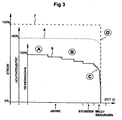
- Function of the display device is therefore essential that the failure characteristic the display device according to the embodiment approximately that of an incandescent lamp arrangement corresponds to how it is based on the schematic characteristic curves 7, 8, 9 in FIG. 3 is shown.
- the time t is plotted to the right, the Time axis is not shown linearly, but the three areas that are completely different in time Year range, hour range and millisecond range. Up are in arbitrary units each have the physical parameters total current, total light intensity and number of intact rows, or secondary branches, where for reasons of the respective 100% values are arranged offset so that they can be better represented. You watch four areas A, B, C and D in the characteristic curves 7, 8, 9.
- Area A corresponds to the normal one Operating state of the display device without any failure
- area B shows the gradually increasing failure of some individual lighting elements or secondary branches, which, however, is not yet an undetected luminosity weakening that is questionable in terms of safety results in area D being the total failure of the display device specified.
- the transition area C with an almost vertical flank is interesting below, which is only the sudden failure of the entire display device after triggering a further securing element deactivated after exceeding the predetermined number Identifies secondary branches.
- This state can be registered by means of a monitoring device 2 customary in technology and reported to a head office. The staff is then asked to identify the person concerned Exchange display device.
Landscapes
- Engineering & Computer Science (AREA)
- Mechanical Engineering (AREA)
- Control Of Indicators Other Than Cathode Ray Tubes (AREA)
- Control Of El Displays (AREA)
Abstract
Description
- Figur 1
- ein schematisches Schaltbild einer Anzeigevorrichtung nach einem bevorzugten Ausführungsbeispiel der Erfindung;
- Figur 2 A und 2 B
- schematische Vorder- und Schnittansichten der Anzeigevorrichtung nach dem Ausführungsbeispiel; und
- Figur 3
- eine schematische Darstellung der Ausfallcharakteristik einer Anzeigevorrichtung nach dem Ausführungsbeispiel.
Claims (10)
- Anzeigevorrichtung für eine sich ändernde Information, wobei die Information durch Auswahl oder Kombination von einzelnen, auf einem Träger (T) angeordneten Leuchtelementen (L) dargestellt wird, wobei die Leuchtelemente durch Halbleiterbauelemente (Dij) ausgebildet sind, insbesondere aus Leuchtdioden oder anderen integrierten Halbleiterschaltungen mit Komponenten zur Lichtemission, und die Halbleiterbauelemente (Dij) in mehreren Schaltungsgruppen geschaltet sind, und jede Schaltungsgruppe strommäßig einen Nebenzweig (Ni) eines Hauptzweiges (H) bildet,
dadurch gekennzeichnet, dass
die aus den Halbleiterbauelementen (Dij) bestehende Schaltung einer Konstantstromeinrichtung (3) dergestalt zugeordnet ist, dass die Summe der in den Nebenzweigen (Ni) fließenden elektrischen Teilströme einen vorbestimmten konstanten Wert besitzt. - Anzeigevorrichtung nach Anspruch 1, dadurch gekennzeichnet, dass die Konstantstromeinrichtung (3) durch eine einzige im Hauptzweig (H) der aus den Halbleiterbauelementen (Dij) gebildeten Schaltung vorgesehene Konstantstromquelle ausgebildet ist.
- Anzeigevorrichtung nach Anspruch 1 oder 2, dadurch gekennzeichnet, dass eine den Halbleiterbauelementen (Dij) zugeordnete Steuerschaltungseinrichtung (F) vorgesehen ist, die bei Überschreitung eines in einem Nebenzweig fließenden Teilstromes um einen vorbestimmten Stromschwellwert eine Sperrung bzw. Deaktivierung des betreffenden Nebenzweiges, und nach Überschreiten einer vorbestimmten Anzahl von gesperrten bzw. deaktivierten Nebenzweige in unmittelbar zeitlicher Folge eine Sperrung bzw. Deaktivierung aller weiteren Nebenzweige und damit der gesamten Anzeigevorrichtung (1) steuert.
- Anzeigevorrichtung nach Anspruch 1 bis 3, dadurch gekennzeichnet, dass die Steuerungsschaltungseinrichtung (F) durch einzelne Sicherungselemente (Fi) in jedem Nebenzweig (Ni) der aus den Halbleiterbauelementen (Dij) gebildeten Schaltung ausgebildet ist.
- Anzeigevorrichtung nach Anspruch 4, dadurch gekennzeichnet, dass die Sicherungselemente (Fi) durch Schmelzsicherungen mit vorbestimmten Durchbruchsstromwerten ausgebildet sind.
- Anzeigevorrichtung nach Anspruch 5, dadurch gekennzeichnet, dass die Halbleiterbauelemente (Dij) eines Nebenzweiges (Ni) nebeneinander in Reihe und mit dem zugehörenden Sicherungselement (Fi) in Reihe geschaltet sind.
- Anzeigevorrichtung nach Anspruch 6, dadurch gekennzeichnet, dass die Nebenzweige (Ni) zueinander parallel geschaltet sind und in einem Knotenpunkt (K) vom Hauptzweig (H) abzweigen.
- Anzeigevorrichtung nach Anspruch 1 bis 7, dadurch gekennzeichnet, dass sie in einer Anlage zur Verkehrs-Regelung, -Steuerung, oder -Überwachung für Straßenfahrzeuge, insbesondere in einer Verkehrsampel verwendet wird.
- Anzeigevorrichtung nach Anspruch 8, dadurch gekennzeichnet, dass die Anlage zur Verkehrs-Regelung, -Steuerung, oder -Überwachung eine der Anzeigevorrichtung (1) nachgeschaltete Überwachungseinrichtung (2) aufweist, welche einen Gesamtausfall der Anzeigevorrichtung (1) erfasst.
- Anzeigevorrichtung nach Anspruch 9, dadurch gekennzeichnet, dass sie ausgangsseitig ein Überwachungssignal für die Überwachungseinrichtung (2) liefert, welches zwei unterschiedliche elektrische Zustände besitzt, wobei der eine Zustand, Betriebszustand, einem ordnungsgemäßen Betrieb der Anzeigevorrichtung (1) und der andere Zustand, Störungszustand, einem Gesamtausfall der Anzeigevorrichtung (1) entspricht.
Applications Claiming Priority (4)
| Application Number | Priority Date | Filing Date | Title |
|---|---|---|---|
| DE19952150 | 1999-10-29 | ||
| DE19952150 | 1999-10-29 | ||
| DE19955743A DE19955743C1 (de) | 1999-10-29 | 1999-11-18 | Anzeigevorrichtung |
| DE19955743 | 1999-11-18 |
Publications (2)
| Publication Number | Publication Date |
|---|---|
| EP1096834A2 true EP1096834A2 (de) | 2001-05-02 |
| EP1096834A3 EP1096834A3 (de) | 2004-07-07 |
Family
ID=26055402
Family Applications (1)
| Application Number | Title | Priority Date | Filing Date |
|---|---|---|---|
| EP00122938A Withdrawn EP1096834A3 (de) | 1999-10-29 | 2000-10-21 | Anzeigevorrichtung mit Leuchtelementen |
Country Status (1)
| Country | Link |
|---|---|
| EP (1) | EP1096834A3 (de) |
Cited By (5)
| Publication number | Priority date | Publication date | Assignee | Title |
|---|---|---|---|---|
| EP1337130A2 (de) * | 2002-02-15 | 2003-08-20 | Garufo GmbH | Anzeigevorrichtung |
| EP1460884A2 (de) * | 2003-03-19 | 2004-09-22 | Eastman Kodak Company | Serie/Parallel oled Lichtquelle |
| AT500039A3 (de) * | 2002-09-20 | 2006-04-15 | Osram Opto Semiconductors Gmbh | Schaltungsanordnung mit einer led-anordnung |
| CN100459822C (zh) * | 2004-06-28 | 2009-02-04 | 江苏英特曼电器有限公司 | 城市灯光监控管理系统 |
| ITPD20110371A1 (it) * | 2011-11-23 | 2013-05-24 | Automotive Lighting Italia S P A A Socio Unico | Circuito di pilotaggio di led, metodo di pilotaggio e fanale automobilistico |
Family Cites Families (2)
| Publication number | Priority date | Publication date | Assignee | Title |
|---|---|---|---|---|
| JPS556687A (en) * | 1978-06-29 | 1980-01-18 | Handotai Kenkyu Shinkokai | Traffic use display |
| CA2225005A1 (en) * | 1997-12-17 | 1999-06-17 | Gelcore Llc | Led lamp with a fault-indicating empedance-changing circuit |
-
2000
- 2000-10-21 EP EP00122938A patent/EP1096834A3/de not_active Withdrawn
Non-Patent Citations (1)
| Title |
|---|
| None * |
Cited By (8)
| Publication number | Priority date | Publication date | Assignee | Title |
|---|---|---|---|---|
| EP1337130A2 (de) * | 2002-02-15 | 2003-08-20 | Garufo GmbH | Anzeigevorrichtung |
| EP1337130A3 (de) * | 2002-02-15 | 2006-05-10 | Garufo GmbH | Anzeigevorrichtung |
| AT500039A3 (de) * | 2002-09-20 | 2006-04-15 | Osram Opto Semiconductors Gmbh | Schaltungsanordnung mit einer led-anordnung |
| EP1460884A2 (de) * | 2003-03-19 | 2004-09-22 | Eastman Kodak Company | Serie/Parallel oled Lichtquelle |
| EP1460884A3 (de) * | 2003-03-19 | 2008-07-16 | Eastman Kodak Company | Serie/Parallel oled Lichtquelle |
| CN100459822C (zh) * | 2004-06-28 | 2009-02-04 | 江苏英特曼电器有限公司 | 城市灯光监控管理系统 |
| ITPD20110371A1 (it) * | 2011-11-23 | 2013-05-24 | Automotive Lighting Italia S P A A Socio Unico | Circuito di pilotaggio di led, metodo di pilotaggio e fanale automobilistico |
| WO2013076685A1 (en) * | 2011-11-23 | 2013-05-30 | Automotive Lighting Italia S.P.A. A Socio Unico | Led driver circuit, driving method and vehicle light |
Also Published As
| Publication number | Publication date |
|---|---|
| EP1096834A3 (de) | 2004-07-07 |
Similar Documents
| Publication | Publication Date | Title |
|---|---|---|
| DE102005047610B4 (de) | Beleuchtungssteuerschaltung für Fahrzeuglampen | |
| DE602004011177T2 (de) | Elektrische Stromversorgungseinrichtung für Leuchtdioden und Scheinwerfer, der eine solche Stromversorgungseinrichtung enthält | |
| DE19705776A1 (de) | Beleuchtungsschaltkreis für eine Entladungslampe | |
| DE60017709T2 (de) | Anordnung zur Fernüberwachung von Led Leuchten | |
| DE10103611B4 (de) | Schaltungsanordnung zum Betreiben von mehreren Leuchtmitteln | |
| WO2010121806A1 (de) | Schaltung für eine leuchtdiodenanordnung und leuchtdiodenmodul | |
| DE10102352C2 (de) | Schaltungsanordnung zur Kennlinienanpassung einer Leuchtdiodenanordnung, Leuchtdioden-Signallampe und Leuchtsignalanordnung sowie deren Verwendung | |
| EP0992961B1 (de) | Schaltungsanordnung zum Betreiben eines Leuchtzeichens | |
| DE102008037551B4 (de) | Vorrichtung zum Betreiben von Leuchtdiodenketten | |
| DE102010003506B4 (de) | LED-Clusterschaltung mit Fehlerdetektion, LED-Leuchte und Beleuchtungssystem | |
| DE102006018813A1 (de) | Fahrzeugleuchtenanordnung | |
| EP2633738B2 (de) | Verbund aus einem bordnetzsteuergerät und wenigstens einem lichtsteuergerät eines kraftfahrzeugs | |
| EP1096834A2 (de) | Anzeigevorrichtung mit Leuchtelementen | |
| EP3124988B1 (de) | Leuchtdioden-steuerungsschaltung für einen signalgeber einer lichtsignalanlage | |
| DE19955743C1 (de) | Anzeigevorrichtung | |
| DE1488996A1 (de) | Photoelektrische Steuereinrichtung,insbesondere zur Ausloesung eines elektrischen Selbstschalters | |
| DE10121380A1 (de) | Elektronisch abgesicherte Stromversorgung für Schaltungsgruppen, Anzeigevorrichtung für eine sich ändernde Information | |
| WO2008065018A1 (de) | Schaltungsanordnung und verfahren zur ausfallsicherung einer led-oder oled-kette | |
| EP1337130A2 (de) | Anzeigevorrichtung | |
| EP1286571A2 (de) | Elektronisch abgesicherte Stromversorgung für Schaltungsgruppen und Anzeigevorrichtung für eine sich änderende Information | |
| EP1341402A2 (de) | Beleuchtungsanordnung mit einem LED-Modul | |
| DE60209677T2 (de) | Lichtinformationseinrichtung zum Anzeigen des Betriebszustandes eines Systems, insbesondere für die Avionics | |
| EP2866524B1 (de) | Anordnung und Verfahren zur Überwachung mehrerer LED-Stränge sowie LED-Leuchte mit einer solchen Anordnung | |
| DE102016121930A1 (de) | Leuchtsystem | |
| EP2882260A1 (de) | Überwachungsschutzschaltung für Beleuchtungsanlagen |
Legal Events
| Date | Code | Title | Description |
|---|---|---|---|
| PUAI | Public reference made under article 153(3) epc to a published international application that has entered the european phase |
Free format text: ORIGINAL CODE: 0009012 |
|
| AK | Designated contracting states |
Kind code of ref document: A2 Designated state(s): AT BE CH CY DE DK ES FI FR GB GR IE IT LI LU MC NL PT SE |
|
| AX | Request for extension of the european patent |
Free format text: AL;LT;LV;MK;RO;SI |
|
| PUAL | Search report despatched |
Free format text: ORIGINAL CODE: 0009013 |
|
| AK | Designated contracting states |
Kind code of ref document: A3 Designated state(s): AT BE CH CY DE DK ES FI FR GB GR IE IT LI LU MC NL PT SE |
|
| AX | Request for extension of the european patent |
Extension state: AL LT LV MK RO SI |
|
| RIC1 | Information provided on ipc code assigned before grant |
Ipc: 7G 08G 1/095 B Ipc: 7H 05B 33/08 A |
|
| 17P | Request for examination filed |
Effective date: 20041228 |
|
| AKX | Designation fees paid |
Designated state(s): AT BE CH CY DE DK ES FI FR GB GR IE IT LI LU MC NL PT SE |
|
| 17Q | First examination report despatched |
Effective date: 20060721 |
|
| GRAP | Despatch of communication of intention to grant a patent |
Free format text: ORIGINAL CODE: EPIDOSNIGR1 |
|
| STAA | Information on the status of an ep patent application or granted ep patent |
Free format text: STATUS: THE APPLICATION IS DEEMED TO BE WITHDRAWN |
|
| 18D | Application deemed to be withdrawn |
Effective date: 20070807 |