EP1096636A2 - Battery pack controlling apparatus - Google Patents
Battery pack controlling apparatus Download PDFInfo
- Publication number
- EP1096636A2 EP1096636A2 EP00123108A EP00123108A EP1096636A2 EP 1096636 A2 EP1096636 A2 EP 1096636A2 EP 00123108 A EP00123108 A EP 00123108A EP 00123108 A EP00123108 A EP 00123108A EP 1096636 A2 EP1096636 A2 EP 1096636A2
- Authority
- EP
- European Patent Office
- Prior art keywords
- battery pack
- battery
- unusual
- section
- detection section
- Prior art date
- Legal status (The legal status is an assumption and is not a legal conclusion. Google has not performed a legal analysis and makes no representation as to the accuracy of the status listed.)
- Granted
Links
Images


Classifications
-
- H—ELECTRICITY
- H02—GENERATION; CONVERSION OR DISTRIBUTION OF ELECTRIC POWER
- H02J—ELECTRIC POWER NETWORKS; CIRCUIT ARRANGEMENTS OR SYSTEMS FOR SUPPLYING OR DISTRIBUTING ELECTRIC POWER; SYSTEMS FOR STORING ELECTRIC ENERGY
- H02J7/00—Circuit arrangements for charging or discharging batteries or for supplying loads from batteries
- H02J7/50—Circuit arrangements for charging or discharging batteries or for supplying loads from batteries acting upon multiple batteries simultaneously or sequentially
- H02J7/52—Circuit arrangements for charging or discharging batteries or for supplying loads from batteries acting upon multiple batteries simultaneously or sequentially for charge balancing, e.g. equalisation of charge between batteries
-
- B—PERFORMING OPERATIONS; TRANSPORTING
- B60—VEHICLES IN GENERAL
- B60L—PROPULSION OF ELECTRICALLY-PROPELLED VEHICLES; SUPPLYING ELECTRIC POWER FOR AUXILIARY EQUIPMENT OF ELECTRICALLY-PROPELLED VEHICLES; ELECTRODYNAMIC BRAKE SYSTEMS FOR VEHICLES IN GENERAL; MAGNETIC SUSPENSION OR LEVITATION FOR VEHICLES; MONITORING OPERATING VARIABLES OF ELECTRICALLY-PROPELLED VEHICLES; ELECTRIC SAFETY DEVICES FOR ELECTRICALLY-PROPELLED VEHICLES
- B60L3/00—Electric devices on electrically-propelled vehicles for safety purposes; Monitoring operating variables, e.g. speed, deceleration or energy consumption
- B60L3/0023—Detecting, eliminating, remedying or compensating for drive train abnormalities, e.g. failures within the drive train
- B60L3/0046—Detecting, eliminating, remedying or compensating for drive train abnormalities, e.g. failures within the drive train relating to electric energy storage systems, e.g. batteries or capacitors
-
- B—PERFORMING OPERATIONS; TRANSPORTING
- B60—VEHICLES IN GENERAL
- B60L—PROPULSION OF ELECTRICALLY-PROPELLED VEHICLES; SUPPLYING ELECTRIC POWER FOR AUXILIARY EQUIPMENT OF ELECTRICALLY-PROPELLED VEHICLES; ELECTRODYNAMIC BRAKE SYSTEMS FOR VEHICLES IN GENERAL; MAGNETIC SUSPENSION OR LEVITATION FOR VEHICLES; MONITORING OPERATING VARIABLES OF ELECTRICALLY-PROPELLED VEHICLES; ELECTRIC SAFETY DEVICES FOR ELECTRICALLY-PROPELLED VEHICLES
- B60L50/00—Electric propulsion with power supplied within the vehicle
- B60L50/50—Electric propulsion with power supplied within the vehicle using propulsion power supplied by batteries or fuel cells
- B60L50/60—Electric propulsion with power supplied within the vehicle using propulsion power supplied by batteries or fuel cells using power supplied by batteries
- B60L50/61—Electric propulsion with power supplied within the vehicle using propulsion power supplied by batteries or fuel cells using power supplied by batteries by batteries charged by engine-driven generators, e.g. series hybrid electric vehicles
-
- B—PERFORMING OPERATIONS; TRANSPORTING
- B60—VEHICLES IN GENERAL
- B60L—PROPULSION OF ELECTRICALLY-PROPELLED VEHICLES; SUPPLYING ELECTRIC POWER FOR AUXILIARY EQUIPMENT OF ELECTRICALLY-PROPELLED VEHICLES; ELECTRODYNAMIC BRAKE SYSTEMS FOR VEHICLES IN GENERAL; MAGNETIC SUSPENSION OR LEVITATION FOR VEHICLES; MONITORING OPERATING VARIABLES OF ELECTRICALLY-PROPELLED VEHICLES; ELECTRIC SAFETY DEVICES FOR ELECTRICALLY-PROPELLED VEHICLES
- B60L58/00—Methods or circuit arrangements for monitoring or controlling batteries or fuel cells, specially adapted for electric vehicles
- B60L58/10—Methods or circuit arrangements for monitoring or controlling batteries or fuel cells, specially adapted for electric vehicles for monitoring or controlling batteries
- B60L58/12—Methods or circuit arrangements for monitoring or controlling batteries or fuel cells, specially adapted for electric vehicles for monitoring or controlling batteries responding to state of charge [SoC]
-
- B—PERFORMING OPERATIONS; TRANSPORTING
- B60—VEHICLES IN GENERAL
- B60L—PROPULSION OF ELECTRICALLY-PROPELLED VEHICLES; SUPPLYING ELECTRIC POWER FOR AUXILIARY EQUIPMENT OF ELECTRICALLY-PROPELLED VEHICLES; ELECTRODYNAMIC BRAKE SYSTEMS FOR VEHICLES IN GENERAL; MAGNETIC SUSPENSION OR LEVITATION FOR VEHICLES; MONITORING OPERATING VARIABLES OF ELECTRICALLY-PROPELLED VEHICLES; ELECTRIC SAFETY DEVICES FOR ELECTRICALLY-PROPELLED VEHICLES
- B60L58/00—Methods or circuit arrangements for monitoring or controlling batteries or fuel cells, specially adapted for electric vehicles
- B60L58/10—Methods or circuit arrangements for monitoring or controlling batteries or fuel cells, specially adapted for electric vehicles for monitoring or controlling batteries
- B60L58/18—Methods or circuit arrangements for monitoring or controlling batteries or fuel cells, specially adapted for electric vehicles for monitoring or controlling batteries of two or more battery modules
- B60L58/22—Balancing the charge of battery modules
-
- B—PERFORMING OPERATIONS; TRANSPORTING
- B60—VEHICLES IN GENERAL
- B60L—PROPULSION OF ELECTRICALLY-PROPELLED VEHICLES; SUPPLYING ELECTRIC POWER FOR AUXILIARY EQUIPMENT OF ELECTRICALLY-PROPELLED VEHICLES; ELECTRODYNAMIC BRAKE SYSTEMS FOR VEHICLES IN GENERAL; MAGNETIC SUSPENSION OR LEVITATION FOR VEHICLES; MONITORING OPERATING VARIABLES OF ELECTRICALLY-PROPELLED VEHICLES; ELECTRIC SAFETY DEVICES FOR ELECTRICALLY-PROPELLED VEHICLES
- B60L58/00—Methods or circuit arrangements for monitoring or controlling batteries or fuel cells, specially adapted for electric vehicles
- B60L58/10—Methods or circuit arrangements for monitoring or controlling batteries or fuel cells, specially adapted for electric vehicles for monitoring or controlling batteries
- B60L58/24—Methods or circuit arrangements for monitoring or controlling batteries or fuel cells, specially adapted for electric vehicles for monitoring or controlling batteries for controlling the temperature of batteries
-
- H—ELECTRICITY
- H02—GENERATION; CONVERSION OR DISTRIBUTION OF ELECTRIC POWER
- H02J—ELECTRIC POWER NETWORKS; CIRCUIT ARRANGEMENTS OR SYSTEMS FOR SUPPLYING OR DISTRIBUTING ELECTRIC POWER; SYSTEMS FOR STORING ELECTRIC ENERGY
- H02J7/00—Circuit arrangements for charging or discharging batteries or for supplying loads from batteries
- H02J7/60—Circuit arrangements for charging or discharging batteries or for supplying loads from batteries including safety or protection arrangements
- H02J7/65—Circuit arrangements for charging or discharging batteries or for supplying loads from batteries including safety or protection arrangements against overtemperature
-
- B—PERFORMING OPERATIONS; TRANSPORTING
- B60—VEHICLES IN GENERAL
- B60L—PROPULSION OF ELECTRICALLY-PROPELLED VEHICLES; SUPPLYING ELECTRIC POWER FOR AUXILIARY EQUIPMENT OF ELECTRICALLY-PROPELLED VEHICLES; ELECTRODYNAMIC BRAKE SYSTEMS FOR VEHICLES IN GENERAL; MAGNETIC SUSPENSION OR LEVITATION FOR VEHICLES; MONITORING OPERATING VARIABLES OF ELECTRICALLY-PROPELLED VEHICLES; ELECTRIC SAFETY DEVICES FOR ELECTRICALLY-PROPELLED VEHICLES
- B60L2210/00—Converter types
- B60L2210/30—AC to DC converters
-
- B—PERFORMING OPERATIONS; TRANSPORTING
- B60—VEHICLES IN GENERAL
- B60L—PROPULSION OF ELECTRICALLY-PROPELLED VEHICLES; SUPPLYING ELECTRIC POWER FOR AUXILIARY EQUIPMENT OF ELECTRICALLY-PROPELLED VEHICLES; ELECTRODYNAMIC BRAKE SYSTEMS FOR VEHICLES IN GENERAL; MAGNETIC SUSPENSION OR LEVITATION FOR VEHICLES; MONITORING OPERATING VARIABLES OF ELECTRICALLY-PROPELLED VEHICLES; ELECTRIC SAFETY DEVICES FOR ELECTRICALLY-PROPELLED VEHICLES
- B60L2210/00—Converter types
- B60L2210/40—DC to AC converters
-
- B—PERFORMING OPERATIONS; TRANSPORTING
- B60—VEHICLES IN GENERAL
- B60L—PROPULSION OF ELECTRICALLY-PROPELLED VEHICLES; SUPPLYING ELECTRIC POWER FOR AUXILIARY EQUIPMENT OF ELECTRICALLY-PROPELLED VEHICLES; ELECTRODYNAMIC BRAKE SYSTEMS FOR VEHICLES IN GENERAL; MAGNETIC SUSPENSION OR LEVITATION FOR VEHICLES; MONITORING OPERATING VARIABLES OF ELECTRICALLY-PROPELLED VEHICLES; ELECTRIC SAFETY DEVICES FOR ELECTRICALLY-PROPELLED VEHICLES
- B60L2240/00—Control parameters of input or output; Target parameters
- B60L2240/40—Drive Train control parameters
- B60L2240/54—Drive Train control parameters related to batteries
- B60L2240/545—Temperature
-
- B—PERFORMING OPERATIONS; TRANSPORTING
- B60—VEHICLES IN GENERAL
- B60L—PROPULSION OF ELECTRICALLY-PROPELLED VEHICLES; SUPPLYING ELECTRIC POWER FOR AUXILIARY EQUIPMENT OF ELECTRICALLY-PROPELLED VEHICLES; ELECTRODYNAMIC BRAKE SYSTEMS FOR VEHICLES IN GENERAL; MAGNETIC SUSPENSION OR LEVITATION FOR VEHICLES; MONITORING OPERATING VARIABLES OF ELECTRICALLY-PROPELLED VEHICLES; ELECTRIC SAFETY DEVICES FOR ELECTRICALLY-PROPELLED VEHICLES
- B60L2240/00—Control parameters of input or output; Target parameters
- B60L2240/40—Drive Train control parameters
- B60L2240/54—Drive Train control parameters related to batteries
- B60L2240/547—Voltage
-
- B—PERFORMING OPERATIONS; TRANSPORTING
- B60—VEHICLES IN GENERAL
- B60L—PROPULSION OF ELECTRICALLY-PROPELLED VEHICLES; SUPPLYING ELECTRIC POWER FOR AUXILIARY EQUIPMENT OF ELECTRICALLY-PROPELLED VEHICLES; ELECTRODYNAMIC BRAKE SYSTEMS FOR VEHICLES IN GENERAL; MAGNETIC SUSPENSION OR LEVITATION FOR VEHICLES; MONITORING OPERATING VARIABLES OF ELECTRICALLY-PROPELLED VEHICLES; ELECTRIC SAFETY DEVICES FOR ELECTRICALLY-PROPELLED VEHICLES
- B60L2240/00—Control parameters of input or output; Target parameters
- B60L2240/40—Drive Train control parameters
- B60L2240/54—Drive Train control parameters related to batteries
- B60L2240/549—Current
-
- Y—GENERAL TAGGING OF NEW TECHNOLOGICAL DEVELOPMENTS; GENERAL TAGGING OF CROSS-SECTIONAL TECHNOLOGIES SPANNING OVER SEVERAL SECTIONS OF THE IPC; TECHNICAL SUBJECTS COVERED BY FORMER USPC CROSS-REFERENCE ART COLLECTIONS [XRACs] AND DIGESTS
- Y02—TECHNOLOGIES OR APPLICATIONS FOR MITIGATION OR ADAPTATION AGAINST CLIMATE CHANGE
- Y02T—CLIMATE CHANGE MITIGATION TECHNOLOGIES RELATED TO TRANSPORTATION
- Y02T10/00—Road transport of goods or passengers
- Y02T10/60—Other road transportation technologies with climate change mitigation effect
- Y02T10/62—Hybrid vehicles
-
- Y—GENERAL TAGGING OF NEW TECHNOLOGICAL DEVELOPMENTS; GENERAL TAGGING OF CROSS-SECTIONAL TECHNOLOGIES SPANNING OVER SEVERAL SECTIONS OF THE IPC; TECHNICAL SUBJECTS COVERED BY FORMER USPC CROSS-REFERENCE ART COLLECTIONS [XRACs] AND DIGESTS
- Y02—TECHNOLOGIES OR APPLICATIONS FOR MITIGATION OR ADAPTATION AGAINST CLIMATE CHANGE
- Y02T—CLIMATE CHANGE MITIGATION TECHNOLOGIES RELATED TO TRANSPORTATION
- Y02T10/00—Road transport of goods or passengers
- Y02T10/60—Other road transportation technologies with climate change mitigation effect
- Y02T10/70—Energy storage systems for electromobility, e.g. batteries
-
- Y—GENERAL TAGGING OF NEW TECHNOLOGICAL DEVELOPMENTS; GENERAL TAGGING OF CROSS-SECTIONAL TECHNOLOGIES SPANNING OVER SEVERAL SECTIONS OF THE IPC; TECHNICAL SUBJECTS COVERED BY FORMER USPC CROSS-REFERENCE ART COLLECTIONS [XRACs] AND DIGESTS
- Y02—TECHNOLOGIES OR APPLICATIONS FOR MITIGATION OR ADAPTATION AGAINST CLIMATE CHANGE
- Y02T—CLIMATE CHANGE MITIGATION TECHNOLOGIES RELATED TO TRANSPORTATION
- Y02T10/00—Road transport of goods or passengers
- Y02T10/60—Other road transportation technologies with climate change mitigation effect
- Y02T10/7072—Electromobility specific charging systems or methods for batteries, ultracapacitors, supercapacitors or double-layer capacitors
-
- Y—GENERAL TAGGING OF NEW TECHNOLOGICAL DEVELOPMENTS; GENERAL TAGGING OF CROSS-SECTIONAL TECHNOLOGIES SPANNING OVER SEVERAL SECTIONS OF THE IPC; TECHNICAL SUBJECTS COVERED BY FORMER USPC CROSS-REFERENCE ART COLLECTIONS [XRACs] AND DIGESTS
- Y02—TECHNOLOGIES OR APPLICATIONS FOR MITIGATION OR ADAPTATION AGAINST CLIMATE CHANGE
- Y02T—CLIMATE CHANGE MITIGATION TECHNOLOGIES RELATED TO TRANSPORTATION
- Y02T10/00—Road transport of goods or passengers
- Y02T10/60—Other road transportation technologies with climate change mitigation effect
- Y02T10/72—Electric energy management in electromobility
Definitions
- the present invention relates to a battery pack controlling apparatus.
- the present invention relates to a battery pack controlling apparatus for detecting unusual heating of at least one of a number of cells or battery modules constituting a battery pack.
- Japanese Laid-Open Patent Publication No. 10-270094 discloses an apparatus for detecting unusual heating of a battery.
- a temperature sensor whose electrical resistance rapidly increases with an increase in temperature is externally mounted to each one of a number of cells, and the resistance values of all such temperature sensors in series connection are measured, whereby unusual heating of the cells can be detected.
- the detection of unusual heating of the cells is necessary for security concerns.
- the resistance value of all of the temperature sensors for the entire battery pack is equal to a multiple of the resistance value of each temperature sensor by a factor of the number of cells.
- a battery pack controlling apparatus for controlling input to or output from a battery pack, wherein: the battery pack includes a plurality of blocks in series connection; and each of the plurality of blocks includes a plurality of batteries in series connection, the battery pack controlling apparatus including: a battery power input/output section for controlling input and output of battery power to and from the battery pack; a block voltage detection section for detecting a block voltage of each of the plurality of blocks; a battery current detection section for detecting a battery current of the battery pack; an unusual heating detection section for detecting unusual heating of at least one of the plurality of batteries based on the block voltage and the battery current; and a vehicle controlling section for controlling the battery power input/output section based on results of unusual heating detection by the unusual heating detection section, wherein the unusual heating detection section includes an internal resistance calculation section for calculating an internal resistance of each of the plurality of blocks based on the block voltage and the battery current, and wherein the unusual heating detection section detects unusual heating of the at least one of the plurality
- the battery pack controlling apparatus further includes a battery temperature detection section for detecting a battery temperature of the battery pack; the unusual heating detection section further includes a threshold value setting section for setting the predetermined threshold value based on the battery temperature of the battery pack; and the unusual heating detection section detects unusual heating of the at least one of the plurality of batteries based on the internal resistance of each of the plurality of blocks and the predetermined threshold value as set by the threshold value setting section.
- the vehicle controlling section controls the battery power input/output section in a stepwise manner based on results of unusual heating detection by the unusual heating detection section.
- the unusual heating detection section further includes: a variance calculation section for calculating an average value and a variance ⁇ 2 of the block voltages of the plurality of blocks; and a variance unusual heating detection section for detecting unusual rising of the internal resistance of the at least one of the plurality of batteries based on the block voltage of each of the plurality of blocks, the average value, and the variance ( ⁇ 2 , and wherein the vehicle controlling section controls the battery power input/output section based on results of unusual rising detection by the variance unusual heating detection section.
- the variance unusual heating detection section determines unusual rising of the internal resistance of the at least one of the plurality of batteries when at least one of the block voltages is equal to or greater than a predetermined value at a time of charging or when at least one of the block voltages is equal to or smaller than a predetermined value at a time of discharging.
- the variance calculation section calculates an average voltage difference value representing an average of voltage differences between the block voltage at a first time and the block voltage at a second time as well as a voltage difference variance representing a variance of the voltage differences
- the variance unusual heating detection section detects unusual rising of the internal resistance of the at least one of the plurality of batteries based on the voltage differences, the average voltage difference value, and the voltage difference variance.
- the first time includes a point in time at which the battery current detected by the battery current detection section is substantially zero.
- the unusual heating detection section includes a available capacity unusual heating detection section for detecting unusual rising of the internal resistance of the at least one of the plurality of batteries based on high available capacity diagnosis and low available capacity diagnosis for respective ones of the plurality of blocks, and the vehicle controlling section controls the battery power input/output section based on results of unusual rising detection by the available capacity unusual heating detection section.
- the invention described herein makes possible the advantages of (1) providing an economical battery pack controlling apparatus which obviates the need for mounting a temperature sensor to each one of a number of cells; (2) providing a battery pack controlling apparatus which is capable of controlling the input and output of a battery pack responsive to an increase in the temperature of a cell, so as to prevent the cell from remaining in an abnormal condition; and (3) providing a battery pack controlling apparatus which is capable of controlling the increase in the temperature of cells, so that the entire battery pack can sustain a longer period of use.
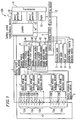
- Figure 1 is a block diagram illustrating an exemplary structure of a battery pack controlling apparatus 100 according to Example 1 of the present invention.
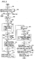
- Figure 2 is a flowchart illustrating the procedure of controlling a battery pack 10 according to Example 1 of the present invention.
- Figure 3 is a flowchart illustrating the procedure of obtaining the voltage, current, and temperature of each block during the control of the battery pack 10 according to Example 1 of the present invention.
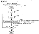
- Figure 4 is a flowchart illustrating the procedure of an internal resistance temperature-correction process during the control of the battery pack 10 according to Example 1 of the present invention.
- Figure 5 is a flowchart illustrating the procedure of a battery input/output restriction signal calculation process during the control of the battery pack 10 according to Example 1 of the present invention.
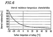
- Figure 6 is a graph illustrating a relationship between the internal resistance and the surface temperature of a battery according to Example 1 of the present invention.
- Figure 7 is a graph showing an exemplary running log of the battery block voltages of a normal battery pack according to Example 1 of the present invention.
- Figure 8 is a graph showing an exemplary running log of the internal resistances of a normal battery pack according to Example 1 of the present invention.
- Figure 9 is a graph showing an exemplary running log of the battery block voltages of a battery pack which includes a cell having abnormal resistance according to Example 1 of the present invention.
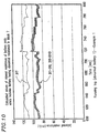
- Figure 10 is a graph showing an exemplary running log of the internal resistances of a battery pack which includes a cell having abnormal resistance according to Example 1 of the present invention.
- Figure 11 is a graph showing another exemplary running log of the battery block voltages of a battery pack which includes a cell having abnormal resistance according to Example 1 of the present invention.
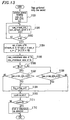
- Figure 12 is a flowchart illustrating the procedure of a battery input/output restriction signal calculation process during the control of a battery pack 10 according to Example 2 of the present invention.
- Figure 13 is a flowchart illustrating the procedure of an unusual heating detection process during the control of a battery pack 10 according to Example 3 of the present invention.
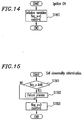
- Figure 14 is a flowchart illustrating the procedure of a variable initialization process during the control of the battery pack 10 according to Example 3 of the present invention.
- Figure 15 is a flowchart illustrating the procedure of a cell abnormality determination process during the control of the battery pack 10 according to Example 3 of the present invention.
- Figure 16 is a graph showing an exemplary running log of the battery block voltages of a normal battery pack according to Example 3 of the present invention.
- Figure 17 is a graph showing an exemplary running log of the battery block voltages of a battery pack which includes a cell having abnormal resistance according to Example 3 of the present invention.
- Figure 18 is a graph illustrating a method for detecting unusual rising of internal resistance according to Example 4 of the present invention.
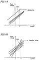
- Figure 19 is a graph illustrating how a misdetection of unusual rising of internal resistance may occur.
- Figure 20 is a graph illustrating a detection failure (or "overlooking") of unusual rising of internal resistance.
- Figure 21 is a graph illustrating a method for detecting unusual rising of internal resistance based on voltage differences according to Example 4 of the present invention.
- Figure 22 is a graph illustrating a method for detecting unusual rising of internal resistance based on voltage differences according to Example 4 of the present invention.
- Figure 23 is a flowchart illustrating the procedure of an unusual heating detection process during the control of a battery pack 10 according to Example 4 of the present invention.
- Figure 24 is a flowchart illustrating the procedure of a variable initialization process during the control of the battery pack 10 according to Example 4 of the present invention.
- Figure 25 is a flowchart illustrating the procedure of a cell abnormality determination process during the control of the battery pack 10 according to Example 4 of the present invention.
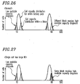
- Figure 26 is a graph illustrating a available capacity distribution of cells in a normal battery pack according to Example 5 of the present invention.
- Figure 27 is a graph illustrating a available capacity distribution of cells in a battery pack which includes a cell having abnormal resistance according to Example 5 of the present invention.
- Figure 28 is a graph illustrating a relationship between a available capacity (SOC) and a block voltage (VB).
- Figure 29 is a graph illustrating a relationship between a battery current (IB) and a block voltage (VB).
- FIG. 1 illustrates an exemplary structure of a battery pack controlling apparatus 100 according to Example 1 of the present invention, where the battery pack controlling apparatus 100 is mounted in a hybrid vehicle.
- the battery pack controlling apparatus 100 controls the input and output of a battery pack 10 .
- the battery pack 10 includes a plurality of blocks 10A which are in series connection.
- Each block 10A includes a plurality of cells 10B which are in series connection.
- the battery pack controlling apparatus 100 includes: a battery power input/output section 1 for controlling the input and output of the battery power to and from the battery pack 10 ; block voltage detection sections 2 , each of which detects the block voltage of an associated block 10A ; a battery current detection section 3 for detecting a battery current of the battery pack 10 ; an unusual heating detection section 4 for detecting an unusual heating of the cells 10B based on the block voltages and the battery current; a vehicle controlling section 5 for controlling the battery power input/output section 1 based on results of the unusual heating detection by the unusual heating detection section 4 ; and a battery temperature detection section 6 for detecting the temperature of the battery pack 10 .
- the unusual heating detection section 4 includes: an internal resistance calculation section 4A for calculating the internal resistance of each of the plurality of blocks 10A based on the block voltage and the battery current; a threshold value setting section 4B for setting a threshold value based on the temperature of the battery pack 10 ; a variance calculation section 4C for calculating an average value and a variance ⁇ 2 of the block voltages of the plurality of blocks 10A ; a variance unusual heating detection section 4D for detecting an unusual heating of one or more cells 10B based on the block voltage of each block 10A as well as the average value and variance ⁇ 2 of the block voltages; and a available capacity unusual heating detection section 4E for detecting an unusual heating of one or more cells 10B based on the available capacity of each block 10A .
- the battery power input/output section 1 includes an inverter 1A and a motor/generator 1B of the hybrid vehicle.
- the motor/generator 1B drives an engine 12 via a transmission 11 .
- An engine controlling section 13 controls the engine 12 based on the output of the vehicle controlling section 5 .
- the vehicle controlling section 5 is coupled to an accelerator pedal 7 , a brake pedal 8 , a shift lever 9 , and a available battery capacity detection section 14.
- the unusual heating detection section 4 detects unusual heating of one or more cells 10B based on the internal resistance of each block 10A and the threshold value which is set by the threshold value setting section 4B .
- the vehicle controlling section 5 controls the battery power input/output section 1 based on the results of unusual heating detection by the unusual heating detection section 4 .
- the vehicle controlling section 5 controls the amount of current supplied to the inverter 1A based on an output from the accelerator pedal 7 , an output from the brake pedal 8 , an output from the shift lever 9 , and an output from the available battery capacity detection section 14 .
- the vehicle controlling section 5 controls the charging and discharging of the battery pack 10 .
- Each block voltage detection section 2 subjects the block voltage of each block 10A to an A/D (analog to digital) conversion.
- the unusual heating detection section 4 detects unusual heating of one or more cells 10B based on the internal resistance of each block 10A and the predetermined threshold value.
- the battery temperature detection section 6 measures the temperature of the battery pack 10 by means of a thermistor, subjects the measured battery temperature to an A/D conversion, and outputs the converted battery temperature value to the unusual heating detection section 4 .
- the threshold value which is set by the threshold value setting section 4B can be determined depending on whether the material composing the cells 10B or any material which the cells 10B are in contact with are suited for a given temperature of the battery pack 10 .
- the threshold value can be set so that any given component element of each cell 10B will be maintained at or below a point of inflection on its characteristic curve, whereby the cell 10B having an elevated IR (internal resistance) value will be prevented from deteriorating acceleratively. As a result, the longevity of the battery pack 10 can be improved.
- the threshold which is to be set by the threshold value setting section 4B can be calculated based on a sum of the heat emission (which is a sum of the heat of reaction and Joule's heat) from a single cell (i.e., a cell 10B ) having an elevated IR value, a thermal capacity of the cell 10B , and the amount of heat which is diffused into the surrounding environment.
- the threshold value which is to be set by the threshold value setting section 4B can be empirically obtained based on an arbitrary cell which is designed so as to provide a relatively large IR value. Once the threshold value is determined, the determined threshold value is reflected in an IR determination threshold value map or an output restriction map.
- the variance unusual heating detection section 4D detects unusual heating of one or more cells 10B based on whether or not at least one of the block voltages is equal to or greater than a predetermined value at the time of charging, or based on whether or not at least one of the block voltages is equal to or smaller than a predetermined value at the time of discharging.
- the vehicle controlling section 5 controls the battery power input/output section 1 based on the results of unusual heating detection by the variance unusual heating detection section 4D .
- conditions 3) and 4) can be detected by a conventional unusual heating detection section which requires a temperature sensor to be mounted on each one of a plurality of cells, and can be prevented from being aggravated by shutting down the input to or output from the battery.
- the internal resistance calculation section 4A calculates the IR (gradient) of each block 10A by a least squares method, based on the I-V characteristics of the battery current and the block voltage of each block 10A during the travel of the vehicle.
- the threshold value setting section 4B sets a threshold value based on the temperature of the battery pack 10 as detected by the temperature detection section 6 .
- the unusual heating detection section 4 outputs a signal for restricting the input to or output frog the battery pack 10 to the vehicle controlling section 5 .
- FIG. 2 is a flowchart illustrating the procedure of controlling the battery pack 10 according to Example 1 of the present invention, in which a number of steps which are performed every one second are shown.
- Figure 3 is a flowchart illustrating the procedure of obtaining the voltage, current, and temperature of each block during the control of the battery pack 10 .
- Figure 4 is a flowchart illustrating the procedure of an internal resistance temperature-correction process.
- Figure 5 is a flowchart illustrating the procedure of a battery input/output restriction signal calculation process.
- Figure 6 is a graph illustrating a relationship between the internal resistance and the surface temperature of a battery.
- a variable TB_BUF represents a TB value input/output buffer.
- a variable ISUM[n] represents a sum of the currents of n blocks during a period of 60 seconds.
- a variable I 2 SUM[n] represents a sum of squares of the currents on the n blocks during the period of 60 seconds.
- a variable TB[i] represents a representative temperature of the battery pack 10 at i seconds as counted from the start of the procedure (where i is an integer from 1 to 60). The representative temperature of the battery pack 10 is acquired by the battery temperature detection section 6 as shown in Figures 1 and 3 .
- a variable VSUM[n] represents a sum of block voltages during the period of 60 seconds.
- a variable V[n,i] represents a block voltage of the n blocks at i seconds as counted from the start of the procedure (where n is an integer from 1 to 10 and; i is an integer from 1 to 60).
- a variable IVSUM[n] represents a sum of multiplication products between the currents and voltages of the n blocks during the period of 60 seconds.
- the block voltage detection section 2 associated with each block 10A detects the voltage of that block 10A ; the battery current detection section 3 detects the current flowing in the battery pack 10 ; and the battery temperature detection section 6 detects the temperature of the battery pack 10 ( S202 ).
- timer variable i is below 60, the procedure is terminated (following the YES path from S203 ). If the timer variable i is equal to or greater than 60 (following the NO path from S203 ), then "0" is substituted for the timer variable i, a block number counter n, and the variable TB_BUF ( S204 ).
- the block number counter n is updated ( S205 ). If the updated value of the block number counter n is equal to or smaller than 10 (following the YES path from S206 ), then "0" is substituted for the variable ISUM[n], the variable I 2 SUM[n], the variable VSUM[n], the variable IVSUM[n], and the internal resistance IR[n] ( S207 ).
- the block number counter n is updated ( S209 ). If the updated block number counter n is equal to or smaller than 10 (following the YES path from S210 ), then the variable TB[i] is added to the variable TB_BUF; the variable I[i] is added to the variable ISUM[n]; and the variable I[i] is added to the variable I 2 SUM[n] (S211).
- the timer variable i is updated ( S212 ), and it is determined whether or not the timer variable i is equal to or smaller than 60 ( S213 ). If the timer variable i is not equal to or smaller than 60, the control returns to S209 .
- variable V[n,i] is added to the variable VSUM[n]; (variable I[i] ⁇ variable V[n,i]) is added to the variable IVSUM[n] ( S214 ); and the control returns to S212 .
- the block number counter n is updated ( S216 ). If the updated block number counter n is equal to or smaller than 10 (following the YES path from S217 ), then the internal resistance IR[n] is calculated based on the variable ISUM, the variable VSUM, the variable IVSUM, and the variable I 2 SUM ( S218 ). Thereafter, the control returns to S216 .
- the timer variable i is cleared to zero ( S219 ), and an internal resistance temperature-correction process (described later) is performed ( S220 ).
- the procedure is terminated. If the available battery capacity is not greater than 30% and not smaller than 80% (following the NO path from S221 ), the procedure is terminated. If the available battery capacity is greater than 30% and is smaller than 80% (following the YES path from S221 ), a battery input/output restriction signal calculation process is performed ( S222 ). The unusual heating detection section 4 outputs a battery input/output value IMAX to the vehicle controlling section 5 ( S223 ), and the procedure is terminated.
- the block number counter n is cleared to zero ( S301 ).
- a block voltage detected by one of the block voltage detection sections 2 is substituted for the variable V[n,i], and the block number counter n is updated ( S302 ). If the block number counter n is equal to or smaller than 10 (following the YES path from S303 ), then S302 is repeated.
- n is not equal to or smaller than 10 (following the NO path from S303 ), then a current value of the battery pack 10 detected by the battery current detection section 3 is substituted for the variable I[i]; the representative temperature of the battery pack 10 detected by the battery temperature detection section 6 is substituted for the variable TB[i] ( S304 ); and the voltage/current/temperature acquisition process for the respective blocks is terminated.
- the internal resistance temperature-correction process ( S220 ) will be described in more detail.
- the block number counter n is cleared to zero ( S401 ).
- the internal resistance IR[n] is corrected based on an internal resistance-temperature characteristics approximation function f(TB) and f(20) ( S403 ).
- the internal resistance is corrected by employing the internal resistance-temperature characteristics approximation function f(TB) because, as shown in Figure 6, the internal resistance varies depending on the battery temperature. If the block number counter n is equal to or smaller than 10 (following the YES path from S404 ), then the control returns to S402 . If the block number counter n is not equal to or smaller than 10 (following the NO path from S404 ), then the internal resistance temperature-correction process is terminated.
- the block number counter n is cleared to zero ( S501 ). After the block number counter n is updated ( S502 ), if the internal resistance IR[n] is not greater than 120 (following the NO path from S503 ), it is determined whether or not the block number counter n is equal to or smaller than 10 ( S504 ).
- the control returns to S502 . If the block number counter n is not equal to or smaller than 10 (following the NO path from S504 ), "1" is substituted for a variable FLAG_CHG and a variable FLAG_DCHG to indicate that no battery input/output restriction signal is output ( S505 ), and the battery input/output restriction signal calculation process is terminated.
- Figure 7 is a graph showing an exemplary running log of the battery block voltages of a normal (i.e., normally operating) battery pack according to Example 1 of the present invention.
- Figure 8 is a graph showing an exemplary running log of the internal resistances of a normal battery pack.
- Figure 9 is a graph showing an exemplary running log of the battery block voltages of a battery pack which includes a cell having abnormal resistance according to Example 1 of the present invention.
- Figure 10 is a graph showing an exemplary running log of the internal resistances of a battery pack which includes a battery having abnormal resistance.
- block voltages VB1 to VB8 associated with eight respective blocks 10A are substantially the same, as shown in Figure 7 .
- the block voltage VB7 associated with a block including the cell having abnormal resistance e.g., block 7 in the example illustrated in Figure 9
- the block voltage VB7 associated with a block including the cell having abnormal resistance has a different value from those of the block voltages VB1 to VB6 and VB8 to VB10 associated with blocks not including any batteries having abnormal resistance (e.g. blocks 1 to 6 and blocks 8 to 10 in the example illustrated in Figure 9 ).
- the internal resistances of the respective blocks of a normal battery pack and those of a battery pack including a battery having abnormal resistance will now be described.
- the internal resistances IR1 to IR10 associated with the respective blocks 10A are substantially the same, as shown in Figure 8 .
- the internal resistance IR7 associated with a block including a battery having abnormal resistance e.g., block 7 in the example illustrated in Figure 10
- Figure 11 is a graph showing another exemplary running log of the battery block voltages of a battery pack including a battery having abnormal resistance.
- the block voltage VB7 associated with a block including a battery having abnormal resistance e.g., block 7 in the example illustrated in Figure 11
- the unusual heating detection section 4 detects unusual heating of one or more cells 10B based on the respective internal resistances of a plurality of blocks 10A and a threshold value, and the vehicle controlling section 5 controls the battery power input/output section 1 based on the results of unusual heating detection by the unusual heating detection section 4 . Therefore, there is no need to mount a temperature sensor on each one of a plurality of cells 10B , so that it is possible to control the battery pack 10 in an economical manner.
- Example 2 of the present invention differs from Example 1 in that the input to or output from the battery pack 10 is controlled or restricted in a stepwise manner.
- the vehicle controlling section 5 controls the battery power input/output section 1 in a stepwise manner based on the results of unusual heating detection by the unusual heating detection section 4 .
- FIG 12 is a flowchart illustrating the procedure of a battery input/output restriction signal calculation process during the control of a battery pack 10 according to Example 2 of the present invention.
- the procedure of controlling the battery pack 10 according to Example 2 is identical with that described in Example 1 with reference to Figures 2 to 5 except for the battery input/output restriction signal calculation process.
- the processes other than the battery input/output restriction signal calculation process, which are identical with their counterparts in Example 1, will not be described herein.
- maximum current values in accordance with the internal resistance is calculated by the processes from steps S1203 to S1212 .
- a minimum value MIN among maximum current values ICHGMAX[1] to ICHGMAX[n] and a minimum value MIN among maximum current values IDCHGMAX[1] to IDCHGMAX[n] are selected by the processes from steps S1203 to S1212 .
- the block number counter n is cleared to zero ( S1203 ).
- the internal resistance IR[n] is equal to or smaller than 140, then it is determined whether or not the internal resistance IR[n] is greater than 120 ( S1206 ). If the internal resistance IR[n] is greater than 120, then "5" is substituted for the variable ICHGMAX[n] and "-5" is substituted for the variable IDCHGMAX[n] ( S1209 ).
- the internal resistance IR[n] is equal to or smaller than 120, then it is determined whether or not the internal resistance IR[n] is greater than 110 ( S1207 ). If the internal resistance IR[n] is greater than 110, then "10" is substituted for the variable ICHGMAX[n] and "-10" is substituted for the variable IDCHGMAX[n] ( S1210 ).
- variable ICHGMAX[n] and the variable IDCHGMAX[n] have been cleared to zero ( S1208 ), or if "5" has been substituted for the variable ICHGMAX[n] and "-5" has been substituted for the variable IDCHGMAX[n] ( S1209 ), or if "10" has been substituted for the variable ICHGMAX[n] and "-10" has been substituted for the variable IDCHGMAX[n] ( S1210 ), then the cell is determined as malfunctioning ( S1211 ).
- the control returns to S1203 . If the block number counter n is not equal to or smaller than 10, then the block number counter n is cleared to zero ( S1213 ).
- variable ICHGMAX is greater than the variable ICHGMAX[n] ( S1215 ). If the variable ICHGMAX is greater than the variable ICHGMAX[n], then the variable ICHGMAX[n] is substituted for the variable ICHGMAX ( S1216 ).
- variable ICHGMAX is not greater than the variable ICHGMAX[n], or if the variable ICHGMAX[n] has been substituted for the variable ICHGMAX, then it is determined whether or not the variable IDCHGMAX is smaller than the variable IDCHGMAX[n] ( S1217 ). If the variable IDCHGMAX is smaller than the variable IDCHGMAX[n], then the variable IDCHGMAX[n] is substituted for the variable IDCHGMAX ( S1218 ).
- variable IDCHGMAX is not smaller than the variable IDCHGMAX[n], or if the variable IDCHGMAX[n] has been substituted for the variable IDCHGMAX, then it is determined whether or not the block number counter n is equal to or smaller than 10 ( S1219 ).
- block number counter n If the block number counter n is equal to or smaller than 10, then the control returns to S1214. If the block number counter n is not equal to or smaller than 10, then a signal is output based on the variables ICHGMAX and IDCHGMAX( S1220 ), and the battery input/output restriction signal calculation process is terminated.
- Example 2 it is possible to restrict a charge or discharge current in a stepwise manner, in accordance with the increase in IR. Therefore, the following effects can be obtained in addition to merely preventing the unusual heating of the cells 10B : 1) Even if the IR of a cell 10B rises to an unusual level, the cell 10B can be controlled so that the temperature of the cell 10B is limited to or below a temperature which is suitable for the elements within the cell 10B .
- the battery pack 10 By detecting the unusual rising of the IR of the cells 10B so as to restrict the input to or output from the cells 10B , it is possible to use the battery pack 10 at or below a temperature over which the performance of the cell 10B would deteriorate acceleratively due to the denaturing of the active material in the cell 10B , whereby the longevity of, the battery pack 10 can be improved.
- the possibilities of internal short-circuiting between the positive and negative electrodes of the cells 10B can be reduced. 2) By detecting the unusual rising of the IR of the cells 10B so as to restrict the input to or output from the cells, 10B , it is possible to continuously use the battery pack 10 while preventing the cell 10B from reaching an abnormal temperature.
- a conventional unusual heating detection apparatus can only detect an abnormality when a cell(s) 10B reaches a predetermined level of a high temperature. Therefore, in applications such as batteries for a hybrid vehicle, for example, it may be necessary to immediately shut down the battery pack 10 upon detection of an abnormality because the battery pack 10 should provide proper motive force for the vehicle.
- Example 2 of the present invention while it is not possible to directly measure an increase in the temperature of a cell 10B , such an increase in the temperature of a cell 10B can be inferred based on the IR value of that cell 10B, and the input to or output from the battery pack 10 can be accordingly restricted in a stepwise manner. This allows the battery pack 10 to be continuously used over prolonged periods of time.
- the IR of a nickel-metal hydride battery or the like tends to be lowered as the battery temperature increases, and this tendency is also common to batteries having an elevated IR value due to malfunctioning. This complicates the determination as to the soundness of the battery, because even if the IR value of such a cell decreases after the vehicle has traveled for some time, such a decrease may be due to an increased temperature of the cell. According to the present example, it is ensured after the start of the procedure shown in Figure 12 that any cell that has previously been determined as malfunctioning will not have its input/output conditions restored, thereby precluding misdetections.
- Example 3 of the present invention differs from Example 1 in that the variance calculation section 4C calculates an average value and a variance ⁇ 2 of the block voltages of a plurality of blocks 10A , and that the variance unusual heating detection section 4D detects unusual heating of one or more cells 10B based on the average value and the variance ⁇ 2 of the block voltages of the plurality of blocks 10A .
- Example 3 the variation of the block voltages of the blocks 10A is subjected to statistical processing, and any block 10A that substantially falls outside the range of the others are determined as malfunctioning, whereupon the input to or output from the battery pack 10 will be restricted.
- the variance unusual heating detection section 4D outputs a signal for restricting the input to or output from the battery pack 10 to the vehicle controlling section 5 if at least one of the block voltages of the blocks 10A is equal to or greater than +2.5 ⁇ 2 at the time of charging, or equal to or smaller than -2.5 ⁇ 2 at the time of discharging.
- Example 3 malfunctioning batteries are determined based on the fact that the cells 10B must in theory be of equal characteristics.
- This technique has an advantage over the technique of applying a standardized threshold value, especially where such a threshold value must be determined by considering complex factors such as the battery temperature, available battery capacity, battery deterioration, and fluctuation in the IR values at low temperatures, which would require a very large amount of data. Trying to address such various factors would increase the cost of experimentation required for obtaining battery characteristics data and the burden on a CPU that calculates the data.
- Figure 13 is a flowchart illustrating the procedure of an unusual heating detection process during the control of a battery pack 10 according to Example 3 of the present invention.
- Figure 14 is a flowchart illustrating the procedure of a variable initialization process during the control of the battery pack 10 .
- Figure 15 is a flowchart illustrating the procedure of a cell abnormality determination process.
- a value obtained by dividing the internal variable sum_v by ten is substituted for a variable ave_v; a value calculated as a function of the internal variable sum_v and the internal variable sum_v2 is substituted for a variable sl; and a value calculated as a function of the variable sl is substituted for a variable s_v ( S1304 ).
- a maximum value of a variable Vn is substituted for a variable max_v; and a minimum value of the variable Vn is substituted for a variable min_v (S1305 ).
- a variable IB is equal to or greater than zero ( S1306 ). If the variable IB is equal to or greater than zero, then it is determined whether or not a value which is obtained by dividing (ave_v - min_v) by the variable s_v is greater than 2.5 ( S1307 ). If the variable IB is smaller than zero, then it is determined whether or not a value which is obtained by dividing (max_v - ave_v) by the variable s_v is greater than 2.5 ( S1308 ).
- a variable flag_v is updated ( S1309 ).
- a variable "count” is updated ( S1310 ). If the variable "count” is 60 (following the YES path from S1311 ), then the cell is determined as abnormal ( S1312 ). If the variable "count” is not 60 (following the NO path from S1311 ), or if the cell has been determined as abnormal, then the unusual heating detection process is terminated.
- variable initialization process will be described.
- the variables flag_v and count are initialized ( S1401 ), and the variable initialization process is terminated.
- a cell abnormality determination process It is determined whether or not the variable flag_v is equal to or greater than 48 ( S1501 ). If the variable flag_v is equal to or greater than 48, then a failure process is performed ( S1502 ). If the variable flag_v is not equal to or greater than 48, or if a failure process has been performed, then the variables flag_v and count are initialized ( S1503 ). and the cell abnormality determination process is terminated.
- Figure 16 is a graph showing an exemplary running log of the battery block voltages of a normal battery pack according to Example 3 of the present invention.
- Figure 17 is a graph showing an exemplary running log of the battery block voltages of a battery pack which includes a battery having abnormal resistance according to Example 3 of the present invention.
- the unusual heating of a cell 10B can be detected based on an evaluation value HC, which in turn is based on the average value and the variance ⁇ 2 of the block voltages of the plurality of blocks 10A .
- the evaluation value HC corresponds to (ave_v - min_v)/s_v or (max_v - ave_v)/s_v used in step S1307 of the unusual heating detection process described above with reference to Figure 13.
- the average value of the block voltages of the blocks 10A corresponds to the variable ave_v.
- the variance ⁇ of the block voltages of the blocks 10A corresponds to the variable s_v.
- the new battery has such a small IR value that its block voltage may not be greater than -2.5 ⁇ 2 at the time of charging.
- the only malfunctioning batteries that can be determined at the time of charging are those in which at least one of the block voltages of the blocks 10A is equal to or greater than +2.5 ⁇ 2 , Thus, misdetection possibilities are eliminated.
- the variance calculation section 4C calculates an average value and a variance ⁇ 2 2 of the block voltages of a plurality of blocks 10A
- the variance unusual heating detection section 4D detects unusual heating of one or more cells 10B based on the average value and the variance ⁇ 2 of the block voltages of the plurality of blocks 10A .
- Example 3 of the present invention can provide satisfactory detection results, whereas a least squares method would not be able to achieve an equally high level of abnormal battery detection accuracy.
- Example 4 of the present invention differs from Example 3 in that the variance calculation section 4C calculates an average voltage difference value representing an average of voltage differences, each measured between a block voltage value of one of a plurality of blocks 10A at a first time and a block voltage value of that block 10A at a second time, as well as a voltage difference variance representing a variance of the voltage differences; and that the variance unusual heating detection section 4D detects unusual rising of the internal resistance of one or more cells 10B based on the voltage differences, the average voltage difference value, and the voltage difference variance.
- Example 4 the voltage differences of the respective block voltages between the first time and the second time are subjected to statistical processing, and any block 10A that substantially falls outside the range of the others is determined as malfunctioning, whereupon the input to or output from the battery pack 10 will be restricted.
- Figure 18 is a graph illustrating a method for detecting unusual rising of internal resistance according to Example 4 of the present invention.
- Figure 19 is a graph illustrating how a misdetection of unusual rising of internal resistance may occur.
- Figure 20 is a graph illustrating a detection failure (or "overlooking") of unusual rising of internal resistance.
- block voltages are subjected to statistical processing such that the internal resistance of any cell 10B that corresponds to a curve 1801 which takes, e.g., a block voltage 1803 on the vertical axis when a current I1 is flowing at time tl is determined to be at an unusual level, because the block voltage 1803 substantially lies outside the distribution pattern 1802 of the rest of the block voltages.
- Detecting instantaneous values of block voltages is susceptible to failure to detect a cell 10B which actually has an unusually high internal resistance, e.g., a cell 10B corresponding to a curve 2001 shown in Figure 20 (a "detection failure" or "overlooking”).
- Figures 21 and 22 are graphs illustrating a method for detecting unusual rising of internal resistance based on voltage differences according to Example 4 of the present invention.
- an unusual rising of the internal resistance of one or more cells 10B is detected based on an average of voltage differences between the respective block voltages of a plurality of blocks 10A at time t1 when a current I1 is flowing and the respective block voltages of the blocks 10A at time t2 when a current I2 is flowing as well as a variance of the voltage differences.
- Example 4 an unusual rising of the internal resistance of one or more cells 10B is detected based on voltage differences between the respective block voltages of a plurality of blocks 10A at time t1 when a current I1 is flowing and the respective block voltages of the blocks 10A at time t2 when a current I2 is flowing, as shown in Figure 21.
- a curve 1901 will be determined as normal unlike in the example illustrated in Figure 19 , thereby preventing misdetections.
- Example 4 an unusual rising of the internal resistance of one or more cells 10B is detected based on voltage differences between the respective block voltages of a plurality of blocks 10A at time t1 when a current I1 is flowing and the respective block voltages of the blocks 10A at time t2 when a current I2 is flowing, as shown in Figure 22 .
- a curve 2001 will be determined as abnormal unlike in the example illustrated in Figure 20 , thereby preventing detection failure.
- Figure 23 is a flowchart illustrating the procedure of an unusual heating detection process during the control of a battery pack 10 according to Example 4 of the present invention.
- Figure 24 is a flowchart illustrating the procedure of a variable initialization process during the control of the battery pack 10 .
- Figure 25 is a flowchart illustrating the procedure of a cell abnormality determination process.
- Example 4 statistical processing of differences between block voltages occurring over a predetermined period of time (e.g., 1 second) is used, rather than instantaneous block voltage values.
- a predetermined period of time e.g. 1 second
- the block voltages at a time when current I1 ⁇ 0 is satisfied may be measured, e.g., at the start of the entire control.
- a voltage difference Vdi between block voltages Vi(t) and Vi(t-1), which are one second apart from each other, is calculated ( S2101 ).
- Internal variables sum_v and sum_v2, and a timer variable i are initialized ( S2102 ).
- a variable Vd_i is added to the internal variable sum_v; (Vdi ⁇ Vdi) is added to the internal variable sum_v2; and the timer variable i is updated ( S2103 ). If the timer variable is not equal to 19 (following the NO path from S2104 ), the process of S2103 is repeated.
- a value obtained by dividing the internal variable sum_v by twenty is substituted for a variable ave_v; a value calculated as a function of the internal variable sum_v and the internal variable sum_v2 is substituted for a variable sl; and a value calculated as a function of the variable sl is substituted for a variable s_v ( S2105 ).
- a maximum value of a variable Vdn is substituted for a variable max_v; and a minimum value of the variable Vdn is substituted for a variable min_v ( S2106 ).
- variable IB It is determined whether or not a variable IB is equal to or greater than zero ( S2107 ). If the variable IB is equal to or greater than zero, then a value obtained by dividing a square of (ave_v - min_v) by a variable VAR_V is substituted for a variable HENSA2 ( S2108 ).
- variable IB is smaller than zero, then a value which is obtained by dividing a square of (max_v - ave_v) by the variable VAR_V is substituted for the variable HENSA2 ( S2110 ).
- a variable flag_v is updated ( S2112 ).
- a variable "count” is updated ( S2113 ). If the variable "count” is 60 (following the YES path from S2114 ), then the cell is determined as abnormal ( S2115 ). If the variable "count” is not 60 (following the NO path from S2114 ), or if the cell has been determined as abnormal, then the unusual heating detection process is terminated.
- variable initialization process a variable initialization process will be described.
- the variables flag_v and count are initialized ( S2201 ), and the variable initialization process is terminated.
- variable flag_v It is determined whether or not the variable flag_v is equal to or greater than 48 ( S2301 ). If the variable flag_v is equal to or greater than 48, then a failure process is performed ( S2302 ) If the variable flag_v is not equal to or greater than 48, or if a failure process has been performed, then the variables flag_v and count are initialized ( S2303 ), and the cell abnormality determination process is terminated.
- the variance calculation section 4C calculates an average voltage difference value representing an average of voltage differences, each measured between a block voltage value of one of a plurality of blocks 10A at a first time and a block voltage value of that block 10A at a second time, as well as a voltage difference variance representing a variance of the voltage differences; and that the variance unusual heating detection section 4D detects unusual rising of the internal resistance of one or more cells 10B based on the voltage differences, the average voltage difference value, and the voltage difference variance.
- misdetections and detection failures are prevented even if the available capacity and the OCVs of the cells 10B happen to vary.
- a battery pack controlling apparatus for univocally determining the available capacity of each block based on the behavior of a battery current and battery voltages is employed in such a manner that, if both a high available capacity diagnosis and a low available capacity diagnosis are given for a given block, that block is determined as abnormal and the input to or output from the battery pack 10 is restricted.
- the available capacity unusual heating detection section 4E detects an unusual heating of one or more cells 10B based on the available capacity of each block 10A .
- the vehicle controlling section 5 controls the battery power input/output section 1 based on the results of unusual heating detection by the available capacity unusual heating detection section 4E .
- Figure 26 is a graph illustrating a available capacity distribution of cells in a normal battery pack according to Example 5 of the present invention.
- Figure 27 is a graph illustrating a available capacity distribution of cells in a battery pack which includes a battery having abnormal resistance.
- Figures 26 and 27 each illustrate a available capacity distribution pattern of blocks including normal ( Figure 26 ) or abnormal ( Figure 27 ) cells 10B in the case where a battery pack 10 is used in a range such that a minimum available capacity of each block 10A is equal to or greater than 10% and a maximum available capacity of each block 10A is equal to or smaller than 90%.
- Figure 28 is a graph illustrating a relationship between a available capacity (SOC) and a block voltage (VB).
- Figure 29 is a graph illustrating a relationship between a battery current (IB) and a block voltage (VB). As seen from Figure 28 , the block voltage of a battery decreases as its available capacity (SOC) decreases.
- the battery current and block voltages change as indicated by a line LM in Figure 29 .
- both the block voltage (VB) and the internal resistance increase as compared to those in the intermediate region; therefore, the battery current and block voltages change as indicated by a line LH in Figure 29 .
- the block voltage (VB) decreases, and the internal resistance increases, as compared to those in the intermediate region; therefore, the battery current and block voltages change as indicated by a line LL in Figure 29 .
- the battery current and block voltages will change as indicated by a line LX in Figure 29 , which intersects the line LH at a point P2 and the line LL at a point P1 .
- a block including any abnormal cells having unusually high internal resistance would qualify for a battery in the high SOC region and for a battery in the low SOC region. Therefore, identifying the available capacity of a block including any abnormal cells having unusually high internal resistance based on the battery current (IB) and the block voltages (VB) might introduce misdetection possibilities.
- IB battery current
- VB block voltages
- the available capacity unusual heating detection section 4E determines that the battery pack is normal if a high available capacity diagnosis and a low available capacity diagnosis are given for respectively different blocks therein.
- the available capacity unusual heating detection section 4E determines unusual heating of the cells 10B included in that block.
- the available capacity unusual heating detection section 4E detects unusual heating of one or more cells 10B based on high available capacity diagnoses and low available capacity diagnoses for a plurality of blocks 10A , and the vehicle controlling section 5 controls the battery power input/output section 1 based on the results of unusual heating detection by the available capacity unusual heating detection section 4E . Therefore, there is no need to mount a temperature sensor on each one of a plurality of cells 10B , so that it is possible to control the battery pack 10 in an economical manner.
- each of the plurality of blocks 10A may instead be composed of a plurality of battery modules.
- an economical battery pack controlling apparatus which obviates the need for mounting a temperature sensor to each one of a number of cells.
- a battery pack controlling apparatus which is capable of controlling the input and output of a battery pack responsive to an increase in the temperature of a cell, so as to prevent the cell from remaining in an abnormal condition.
- a battery pack controlling apparatus which is capable of controlling the increase in the temperature of cells, so that the entire battery pack can sustain a longer period of use.
Landscapes
- Engineering & Computer Science (AREA)
- Power Engineering (AREA)
- Life Sciences & Earth Sciences (AREA)
- Sustainable Development (AREA)
- Sustainable Energy (AREA)
- Transportation (AREA)
- Mechanical Engineering (AREA)
- Secondary Cells (AREA)
- Charge And Discharge Circuits For Batteries Or The Like (AREA)
- Electric Propulsion And Braking For Vehicles (AREA)
Abstract
Description
Internal short circuiting of a
Overcharging of a
1) Even if the IR of a
2) By detecting the unusual rising of the IR of the
Claims (8)
- A battery pack controlling apparatus for controlling input to or output from a battery pack, wherein:the battery pack comprises a plurality of blocks in series connection; andeach of the plurality of blocks includes a plurality of batteries in series connection,the battery pack controlling apparatus comprising:a battery power input/output section for controlling input and output of battery power to and from the battery pack;a block voltage detection section for detecting a block voltage of each of the plurality of blocks;a battery current detection section for detecting a battery current of the battery pack;an unusual heating detection section for detecting unusual heating of at least one of the plurality of batteries based on the block voltage and the battery current; anda vehicle controlling section for controlling the battery power input/output section based on results of unusual heating detection by the unusual heating detection section,wherein the unusual heating detection section includesan internal resistance calculation section for calculating an internal resistance of each of the plurality of blocks based on the block voltage and the battery current, andwherein the unusual heating detection section detects unusual heating of the at least one of the plurality of batteries based on the internal resistance of each of the plurality of blocks and a predetermined threshold value.
- A battery pack controlling apparatus according to claim 1, wherein:the battery pack controlling apparatus further comprises a battery temperature detection section for detecting a battery temperature of the battery pack;the unusual heating detection section further comprises a threshold value setting section for setting the predetermined threshold value based on the battery temperature of the battery pack; andthe unusual heating detection section detects unusual heating of the at least one of the plurality of batteries based on the internal resistance of each of the plurality of blocks and the predetermined threshold value as set by the threshold value setting section.
- A battery pack controlling apparatus according to claim 1, wherein the vehicle controlling section controls the battery power input/output section in a stepwise manner based on results of unusual heating detection by the unusual heating detection section.
- A battery pack controlling apparatus according to claim 1,wherein the unusual heating detection section further comprises:a variance calculation section for calculating an average value and a variance σ2 of the block voltages of the plurality of blocks; anda variance unusual heating detection section for detecting unusual rising of the internal resistance of the at least one of the plurality of batteries based on the block voltage of each of the plurality of blocks, the average value, and the variance σ2, andwherein the vehicle controlling section controls the battery power input/output section based on results of unusual rising detection by the variance unusual heating detection section.
- A battery pack controlling apparatus according to claim 4,
wherein the variance unusual heating detection section determines unusual rising of the internal resistance of the at least one of the plurality of batteries when at least one of the block voltages is equal to or greater than a predetermined value at a time of charging or when at least one of the block voltages is equal to or smaller than a predetermined value at a time of discharging. - A battery pack controlling apparatus according to claim 4,wherein the variance calculation section calculates an average voltage difference value representing an average of voltage differences between the block voltage at a first time and the block voltage at a second time as well as a voltage difference variance representing a variance of the voltage differences, andwherein the variance unusual heating detection section detects unusual rising of the internal resistance of the at least one of the plurality of batteries based on the voltage differences, the average voltage difference value, and the voltage difference variance.
- A battery pack controlling apparatus according to claim 6, wherein the first time comprises a point in time at which the battery current detected by the battery current detection section is substantially zero.
- A battery pack controlling apparatus according to claim 1,wherein the unusual heating detection section comprises a available capacity unusual heating detection section for detecting unusual rising of the internal resistance of the at least one of the plurality of batteries based on high available capacity diagnosis and low available capacity diagnosis for respective ones of the plurality of blocks, andwherein the vehicle controlling section controls the battery power input/output section based on results of unusual rising detection by the available capacity unusual heating detection section.
Applications Claiming Priority (4)
| Application Number | Priority Date | Filing Date | Title |
|---|---|---|---|
| JP30317899 | 1999-10-25 | ||
| JP30317899 | 1999-10-25 | ||
| JP2000322921 | 2000-10-23 | ||
| JP2000322921A JP4009416B2 (en) | 1999-10-25 | 2000-10-23 | Battery pack control device |
Publications (3)
| Publication Number | Publication Date |
|---|---|
| EP1096636A2 true EP1096636A2 (en) | 2001-05-02 |
| EP1096636A3 EP1096636A3 (en) | 2004-06-30 |
| EP1096636B1 EP1096636B1 (en) | 2007-05-02 |
Family
ID=26563427
Family Applications (1)
| Application Number | Title | Priority Date | Filing Date |
|---|---|---|---|
| EP00123108A Expired - Lifetime EP1096636B1 (en) | 1999-10-25 | 2000-10-25 | Battery pack controlling apparatus |
Country Status (5)
| Country | Link |
|---|---|
| US (1) | US6486637B1 (en) |
| EP (1) | EP1096636B1 (en) |
| JP (1) | JP4009416B2 (en) |
| CN (1) | CN1222073C (en) |
| DE (1) | DE60034643T2 (en) |
Cited By (7)
| Publication number | Priority date | Publication date | Assignee | Title |
|---|---|---|---|---|
| EP1293377A3 (en) * | 2001-09-14 | 2004-01-02 | Matsushita Electric Industrial Co., Ltd. | Battery control device |
| EP1349230A3 (en) * | 2002-03-26 | 2006-08-02 | Nissan Motor Company Limited | Power supply unit |
| FR2918027A1 (en) * | 2007-06-28 | 2009-01-02 | Valeo Equip Electr Moteur | METHOD FOR CONTROLLING MICRO-HYBRID SYSTEM FOR VEHICLE, AND ENERGY STORAGE UNIT AND HYBRID SYSTEM FOR IMPLEMENTING SAID SYSTEM |
| WO2010049795A1 (en) * | 2008-10-30 | 2010-05-06 | Toyota Jidosha Kabushiki Kaisha | Battery pack input/output control system |
| WO2012150119A1 (en) * | 2011-05-05 | 2012-11-08 | Sb Limotive Company Ltd. | Method for monitoring the temperature of a battery cell |
| EP2626716A3 (en) * | 2003-06-27 | 2013-11-27 | The Furukawa Electric Co., Ltd. | Device and method for judging deterioration of accumulator / secondary cell |
| CN114585939A (en) * | 2020-05-15 | 2022-06-03 | 株式会社Lg新能源 | Apparatus and method for diagnosing battery |
Families Citing this family (38)
| Publication number | Priority date | Publication date | Assignee | Title |
|---|---|---|---|---|
| JP2003086255A (en) * | 2001-09-12 | 2003-03-20 | Toyota Motor Corp | State estimation method for secondary battery |
| JP3565271B2 (en) | 2001-11-19 | 2004-09-15 | 日産自動車株式会社 | Battery assembly and method of manufacturing the same |
| JP3939546B2 (en) * | 2001-12-06 | 2007-07-04 | パナソニック・イーブイ・エナジー株式会社 | Battery power device for electric vehicle |
| JP4095878B2 (en) * | 2002-10-28 | 2008-06-04 | 松下電器産業株式会社 | Battery management system, battery pack, and charge state measuring method thereof |
| US20070069695A1 (en) * | 2003-07-16 | 2007-03-29 | Cheol-Seob Lee | Power controller for vehicle |
| JP4260121B2 (en) * | 2004-04-09 | 2009-04-30 | 三洋電機株式会社 | Power supply |
| CN100375365C (en) * | 2005-06-30 | 2008-03-12 | 复旦大学 | A battery pack intelligent management circuit structure |
| JP5050325B2 (en) * | 2005-07-12 | 2012-10-17 | 日産自動車株式会社 | Battery control device |
| US7759077B2 (en) * | 2005-08-02 | 2010-07-20 | Shariat Shahrokh F | Soluble fas urinary marker for the detection of bladder transitional cell carcinoma |
| JP2007311065A (en) * | 2006-05-16 | 2007-11-29 | Toyota Motor Corp | Battery device, vehicle mounting this, and abnormality determining method of battery device |
| WO2008096771A1 (en) | 2007-02-08 | 2008-08-14 | Panasonic Ev Energy Co., Ltd. | Device and method for detecting abnormality of electric storage device |
| JP2008204800A (en) * | 2007-02-20 | 2008-09-04 | Matsushita Electric Ind Co Ltd | Non-aqueous electrolyte secondary battery rapid charging method and electronic device using the same |
| JP5245334B2 (en) * | 2007-09-11 | 2013-07-24 | パナソニック株式会社 | Power storage device |
| JP4494453B2 (en) * | 2007-11-13 | 2010-06-30 | トヨタ自動車株式会社 | Secondary battery control device and control method |
| JP5656415B2 (en) * | 2009-03-26 | 2015-01-21 | プライムアースEvエナジー株式会社 | Secondary battery state determination device and control device |
| US8483886B2 (en) * | 2009-09-01 | 2013-07-09 | Boston-Power, Inc. | Large scale battery systems and method of assembly |
| CN102035223B (en) * | 2009-09-29 | 2013-03-27 | 旭隼科技股份有限公司 | Output power tracking control method and device |
| JP5148579B2 (en) | 2009-09-29 | 2013-02-20 | 三菱重工業株式会社 | Secondary battery abnormality prediction system |
| JP5382138B2 (en) * | 2009-12-25 | 2014-01-08 | トヨタ自動車株式会社 | Abnormality detection device for battery pack |
| CN102148390B (en) * | 2010-02-10 | 2013-08-28 | 大连融科储能技术发展有限公司 | Battery system for distributing flow energy storage current or voltage and control method |
| CN102859836B (en) * | 2010-04-28 | 2016-05-18 | 丰田自动车株式会社 | Charging control method and control device for secondary battery |
| KR20110134019A (en) * | 2010-06-08 | 2011-12-14 | 현대자동차주식회사 | How to diagnose cell deterioration of vehicle battery |
| KR101569484B1 (en) | 2010-12-03 | 2015-11-16 | 주식회사 엘지화학 | Apparatus and method for controlling battery pack with temperature information |
| FR2970820B1 (en) * | 2011-01-24 | 2013-01-04 | Renault Sa | METHOD FOR MANAGING THE CHARGE OF A RECHARGEABLE BATTERY OF A MOTOR VEHICLE |
| KR20130013101A (en) * | 2011-07-27 | 2013-02-06 | 현대모비스 주식회사 | Battery sensor and the operation method thereof |
| US9145059B2 (en) * | 2011-09-09 | 2015-09-29 | GM Global Technology Operations LLC | Method and system for estimating cell resistances within a vehicle battery |
| FR2992618B1 (en) * | 2012-06-27 | 2015-10-30 | Renault Sas | METHOD FOR MANAGING ENERGY ON A HYBRID VEHICLE |
| JP5942882B2 (en) * | 2013-02-15 | 2016-06-29 | 株式会社デンソー | Battery system |
| CN103336246B (en) * | 2013-06-28 | 2016-08-24 | 深圳市普禄科智能检测设备有限公司 | Storage battery monitoring device and method |
| JP6102714B2 (en) * | 2013-12-11 | 2017-03-29 | トヨタ自動車株式会社 | Power storage system |
| JP6033210B2 (en) * | 2013-12-12 | 2016-11-30 | 三菱重工業株式会社 | Abnormal state monitoring apparatus, abnormal state monitoring system, abnormal state monitoring method, and program |
| ITUB20169952A1 (en) * | 2016-01-13 | 2017-07-13 | Genport Srl | Electronic regulation device for battery type electrical energy storage devices |
| CN106371350A (en) * | 2016-08-24 | 2017-02-01 | 湖北三江航天红峰控制有限公司 | Isolation circuit and method for multi-channel AD acquisition |
| KR102196270B1 (en) * | 2016-12-12 | 2020-12-29 | 주식회사 엘지화학 | Method and apparatus for detecting short of a battery cell |
| CN111149269B (en) * | 2017-10-04 | 2024-03-29 | 株式会社Aesc日本 | Method and device for inspecting battery pack |
| JP7067909B2 (en) * | 2017-12-04 | 2022-05-16 | トヨタ自動車株式会社 | Rechargeable battery system |
| JP7069837B2 (en) * | 2018-03-02 | 2022-05-18 | トヨタ自動車株式会社 | Battery diagnostic equipment and method |
| MX2021011134A (en) | 2019-03-14 | 2021-12-10 | Generac Power Systems Inc | THERMAL MANAGEMENT OF THE BATTERY MODULE. |
Family Cites Families (13)
| Publication number | Priority date | Publication date | Assignee | Title |
|---|---|---|---|---|
| US4433294A (en) | 1981-06-05 | 1984-02-21 | Firing Circuits, Inc. | Method and apparatus for testing a battery |
| US4692682A (en) * | 1985-12-23 | 1987-09-08 | Levitt Safety Limited | Nicad battery charger |
| US5281919A (en) * | 1988-10-14 | 1994-01-25 | Alliedsignal Inc. | Automotive battery status monitor |
| CA2018639A1 (en) | 1990-06-08 | 1991-12-08 | James D. Blair | Method and apparatus for comparing fuel cell voltage |
| DE4439785C2 (en) * | 1994-11-07 | 1999-05-12 | Mikron Ges Fuer Integrierte Mi | Method for charging a rechargeable battery and device for carrying out the method |
| JPH08140206A (en) | 1994-11-09 | 1996-05-31 | Fuji Heavy Ind Ltd | Battery managing method for electric motor vehicle |
| US5581170A (en) | 1994-12-12 | 1996-12-03 | Unitrode Corporation | Battery protector |
| US5670861A (en) * | 1995-01-17 | 1997-09-23 | Norvik Tractions Inc. | Battery energy monitoring circuits |
| JP3251499B2 (en) | 1996-05-31 | 2002-01-28 | 矢崎総業株式会社 | Battery remaining capacity measurement device |
| JPH114545A (en) | 1997-06-10 | 1999-01-06 | Toyota Autom Loom Works Ltd | Output restricting device for battery |
| AU2089699A (en) * | 1997-12-23 | 1999-07-12 | Amerigon, Inc. | Radio frequency energy management system |
| JP3379444B2 (en) * | 1998-09-07 | 2003-02-24 | トヨタ自動車株式会社 | Hybrid vehicle charge / discharge state control device |
| JP2001023699A (en) | 1999-07-05 | 2001-01-26 | Yazaki Corp | Battery management device |
-
2000
- 2000-10-23 JP JP2000322921A patent/JP4009416B2/en not_active Expired - Fee Related
- 2000-10-25 EP EP00123108A patent/EP1096636B1/en not_active Expired - Lifetime
- 2000-10-25 US US09/696,367 patent/US6486637B1/en not_active Expired - Lifetime
- 2000-10-25 CN CNB00137155XA patent/CN1222073C/en not_active Expired - Lifetime
- 2000-10-25 DE DE60034643T patent/DE60034643T2/en not_active Expired - Lifetime
Cited By (16)
| Publication number | Priority date | Publication date | Assignee | Title |
|---|---|---|---|---|
| US6759832B2 (en) | 2001-09-14 | 2004-07-06 | Matsushita Electric Industrial Co., Ltd. | Device for detecting a battery condition based on variations in batter voltage |
| EP1293377A3 (en) * | 2001-09-14 | 2004-01-02 | Matsushita Electric Industrial Co., Ltd. | Battery control device |
| EP1349230A3 (en) * | 2002-03-26 | 2006-08-02 | Nissan Motor Company Limited | Power supply unit |
| US7115332B2 (en) | 2002-03-26 | 2006-10-03 | Nissan Motor Co., Ltd. | Power supply unit |
| EP2626716A3 (en) * | 2003-06-27 | 2013-11-27 | The Furukawa Electric Co., Ltd. | Device and method for judging deterioration of accumulator / secondary cell |
| CN101778748B (en) * | 2007-06-28 | 2013-11-13 | 法雷奥电机设备公司 | Method for driving a micro-hybrid system for vehicle and an energy storage unit, and hybrid system for implementing same |
| FR2918027A1 (en) * | 2007-06-28 | 2009-01-02 | Valeo Equip Electr Moteur | METHOD FOR CONTROLLING MICRO-HYBRID SYSTEM FOR VEHICLE, AND ENERGY STORAGE UNIT AND HYBRID SYSTEM FOR IMPLEMENTING SAID SYSTEM |
| WO2009001001A3 (en) * | 2007-06-28 | 2009-02-26 | Valeo Equip Electr Moteur | Method for driving a micro-hybrid system for vehicle and an energy storage unit, and hybrid system for implementing same |
| CN101778748A (en) * | 2007-06-28 | 2010-07-14 | 法雷奥电机设备公司 | Method for driving a micro-hybrid system for vehicle and an energy storage unit, and hybrid system for implementing same |
| US8400111B2 (en) | 2007-06-28 | 2013-03-19 | Valeo Equipements Electriques Moteur | Method for driving micro-hybrid system for vehicle and energy storage unit, and hybrid system for implementing the same |
| US8829857B2 (en) | 2008-10-30 | 2014-09-09 | Toyota Jidosha Kabushiki Kaisha | Battery pack input/output control system |
| WO2010049795A1 (en) * | 2008-10-30 | 2010-05-06 | Toyota Jidosha Kabushiki Kaisha | Battery pack input/output control system |
| WO2012150119A1 (en) * | 2011-05-05 | 2012-11-08 | Sb Limotive Company Ltd. | Method for monitoring the temperature of a battery cell |
| CN114585939A (en) * | 2020-05-15 | 2022-06-03 | 株式会社Lg新能源 | Apparatus and method for diagnosing battery |
| EP4040174A4 (en) * | 2020-05-15 | 2023-10-11 | LG Energy Solution, Ltd. | BATTERY DIAGNOSTIC DEVICE AND METHOD |
| US11959969B2 (en) | 2020-05-15 | 2024-04-16 | Lg Energy Solution, Ltd. | Apparatus and method for diagnosing battery |
Also Published As
| Publication number | Publication date |
|---|---|
| JP2001196102A (en) | 2001-07-19 |
| CN1305240A (en) | 2001-07-25 |
| EP1096636A3 (en) | 2004-06-30 |
| JP4009416B2 (en) | 2007-11-14 |
| DE60034643T2 (en) | 2007-09-06 |
| EP1096636B1 (en) | 2007-05-02 |
| CN1222073C (en) | 2005-10-05 |
| DE60034643D1 (en) | 2007-06-14 |
| US6486637B1 (en) | 2002-11-26 |
Similar Documents
| Publication | Publication Date | Title |
|---|---|---|
| EP1096636B1 (en) | Battery pack controlling apparatus | |
| US7514905B2 (en) | Battery management system | |
| US7649338B2 (en) | Method for compensating state of charge of battery and battery management system using the same | |
| EP1265335B1 (en) | Method and apparatus for controlling residual battery capacity of secondary battery | |
| CN100541969C (en) | Method for compensating battery state of charge and battery management system using same | |
| US7355411B2 (en) | Method and apparatus for estimating state of charge of secondary battery | |
| US6984961B2 (en) | Battery assembly system and electric-motor vehicle system using the same | |
| JP3659068B2 (en) | Battery management device | |
| JP6746705B2 (en) | System and method for battery charge control | |
| EP2058891B1 (en) | Charging control device for a storage battery | |
| US20100066379A1 (en) | Abnormality detecting device for storage element, abnormality detecting method for storage element, abnormality detecting program for storage element, and computer-readable recording medium storing abnormality detecting program | |
| WO2008065910A1 (en) | Accumulator failure detecting device, accumulator failure detecting method, accumulator failure detecting program, and computer-readable recording medium containing the accumulator failure detecting program | |
| JP2000092732A (en) | Method for determining variation of assembled battery and battery device | |
| JP4542675B2 (en) | Voltage correction device for battery pack for electric vehicle | |
| JP2000166109A (en) | Battery state-of-charge detection device | |
| EP1340992B1 (en) | Method and apparatus for charge and discharge control of battery pack | |
| KR101065591B1 (en) | Battery management system and method for estimating battery charge state | |
| EP2859636B1 (en) | Accumulator battery protected against external short-circuits | |
| JP2000221249A (en) | Battery state-of-charge detection device | |
| JP2001186682A (en) | Battery discharge control method | |
| US20250175027A1 (en) | Battery control device | |
| JP2025008344A (en) | Battery Management System |
Legal Events
| Date | Code | Title | Description |
|---|---|---|---|
| PUAI | Public reference made under article 153(3) epc to a published international application that has entered the european phase |
Free format text: ORIGINAL CODE: 0009012 |
|
| AK | Designated contracting states |
Kind code of ref document: A2 Designated state(s): AT BE CH CY DE DK ES FI FR GB GR IE IT LI LU MC NL PT SE |
|
| AX | Request for extension of the european patent |
Free format text: AL;LT;LV;MK;RO;SI |
|
| PUAL | Search report despatched |
Free format text: ORIGINAL CODE: 0009013 |
|
| AK | Designated contracting states |
Kind code of ref document: A3 Designated state(s): AT BE CH CY DE DK ES FI FR GB GR IE IT LI LU MC NL PT SE |
|
| AX | Request for extension of the european patent |
Extension state: AL LT LV MK RO SI |
|
| RIC1 | Information provided on ipc code assigned before grant |
Ipc: 7H 02J 7/14 B Ipc: 7H 02J 7/00 A |
|
| 17P | Request for examination filed |
Effective date: 20041229 |
|
| 17Q | First examination report despatched |
Effective date: 20050203 |
|
| AKX | Designation fees paid |
Designated state(s): DE FR GB |
|
| GRAP | Despatch of communication of intention to grant a patent |
Free format text: ORIGINAL CODE: EPIDOSNIGR1 |
|
| GRAS | Grant fee paid |
Free format text: ORIGINAL CODE: EPIDOSNIGR3 |
|
| GRAA | (expected) grant |
Free format text: ORIGINAL CODE: 0009210 |
|
| AK | Designated contracting states |
Kind code of ref document: B1 Designated state(s): DE FR GB |
|
| REG | Reference to a national code |
Ref country code: GB Ref legal event code: FG4D |
|
| REF | Corresponds to: |
Ref document number: 60034643 Country of ref document: DE Date of ref document: 20070614 Kind code of ref document: P |
|
| ET | Fr: translation filed | ||
| PLBE | No opposition filed within time limit |
Free format text: ORIGINAL CODE: 0009261 |
|
| STAA | Information on the status of an ep patent application or granted ep patent |
Free format text: STATUS: NO OPPOSITION FILED WITHIN TIME LIMIT |
|
| 26N | No opposition filed |
Effective date: 20080205 |
|
| REG | Reference to a national code |
Ref country code: DE Ref legal event code: R084 Ref document number: 60034643 Country of ref document: DE |
|
| REG | Reference to a national code |
Ref country code: GB Ref legal event code: 746 Effective date: 20160809 |
|
| REG | Reference to a national code |
Ref country code: FR Ref legal event code: PLFP Year of fee payment: 17 |
|
| REG | Reference to a national code |
Ref country code: FR Ref legal event code: PLFP Year of fee payment: 18 |
|
| REG | Reference to a national code |
Ref country code: FR Ref legal event code: PLFP Year of fee payment: 19 |
|
| PGFP | Annual fee paid to national office [announced via postgrant information from national office to epo] |
Ref country code: FR Payment date: 20190913 Year of fee payment: 20 |
|
| PGFP | Annual fee paid to national office [announced via postgrant information from national office to epo] |
Ref country code: DE Payment date: 20191015 Year of fee payment: 20 |
|
| PGFP | Annual fee paid to national office [announced via postgrant information from national office to epo] |
Ref country code: GB Payment date: 20191025 Year of fee payment: 20 |
|
| REG | Reference to a national code |
Ref country code: DE Ref legal event code: R071 Ref document number: 60034643 Country of ref document: DE |
|
| REG | Reference to a national code |
Ref country code: GB Ref legal event code: PE20 Expiry date: 20201024 |
|
| PG25 | Lapsed in a contracting state [announced via postgrant information from national office to epo] |
Ref country code: GB Free format text: LAPSE BECAUSE OF EXPIRATION OF PROTECTION Effective date: 20201024 |