EP1096621A1 - Electric connector - Google Patents
Electric connector Download PDFInfo
- Publication number
- EP1096621A1 EP1096621A1 EP00123864A EP00123864A EP1096621A1 EP 1096621 A1 EP1096621 A1 EP 1096621A1 EP 00123864 A EP00123864 A EP 00123864A EP 00123864 A EP00123864 A EP 00123864A EP 1096621 A1 EP1096621 A1 EP 1096621A1
- Authority
- EP
- European Patent Office
- Prior art keywords
- connector
- circuit board
- pin
- print circuit
- auto fuse
- Prior art date
- Legal status (The legal status is an assumption and is not a legal conclusion. Google has not performed a legal analysis and makes no representation as to the accuracy of the status listed.)
- Granted
Links
- 238000006243 chemical reaction Methods 0.000 description 8
- 238000005476 soldering Methods 0.000 description 5
- 238000007598 dipping method Methods 0.000 description 4
- 229910000679 solder Inorganic materials 0.000 description 4
- 230000005236 sound signal Effects 0.000 description 3
- 239000004020 conductor Substances 0.000 description 2
- 239000011810 insulating material Substances 0.000 description 2
- 230000000149 penetrating effect Effects 0.000 description 2
- 239000011347 resin Substances 0.000 description 2
- 229920005989 resin Polymers 0.000 description 2
- 230000006866 deterioration Effects 0.000 description 1
- 238000000034 method Methods 0.000 description 1
Images





Classifications
-
- H—ELECTRICITY
- H01—ELECTRIC ELEMENTS
- H01R—ELECTRICALLY-CONDUCTIVE CONNECTIONS; STRUCTURAL ASSOCIATIONS OF A PLURALITY OF MUTUALLY-INSULATED ELECTRICAL CONNECTING ELEMENTS; COUPLING DEVICES; CURRENT COLLECTORS
- H01R31/00—Coupling parts supported only by co-operation with counterpart
-
- H—ELECTRICITY
- H01—ELECTRIC ELEMENTS
- H01R—ELECTRICALLY-CONDUCTIVE CONNECTIONS; STRUCTURAL ASSOCIATIONS OF A PLURALITY OF MUTUALLY-INSULATED ELECTRICAL CONNECTING ELEMENTS; COUPLING DEVICES; CURRENT COLLECTORS
- H01R12/00—Structural associations of a plurality of mutually-insulated electrical connecting elements, specially adapted for printed circuits, e.g. printed circuit boards [PCB], flat or ribbon cables, or like generally planar structures, e.g. terminal strips, terminal blocks; Coupling devices specially adapted for printed circuits, flat or ribbon cables, or like generally planar structures; Terminals specially adapted for contact with, or insertion into, printed circuits, flat or ribbon cables, or like generally planar structures
- H01R12/70—Coupling devices
- H01R12/71—Coupling devices for rigid printing circuits or like structures
- H01R12/712—Coupling devices for rigid printing circuits or like structures co-operating with the surface of the printed circuit or with a coupling device exclusively provided on the surface of the printed circuit
- H01R12/716—Coupling device provided on the PCB
-
- H—ELECTRICITY
- H01—ELECTRIC ELEMENTS
- H01H—ELECTRIC SWITCHES; RELAYS; SELECTORS; EMERGENCY PROTECTIVE DEVICES
- H01H85/00—Protective devices in which the current flows through a part of fusible material and this current is interrupted by displacement of the fusible material when this current becomes excessive
- H01H85/02—Details
- H01H85/20—Bases for supporting the fuse; Separate parts thereof
- H01H2085/2075—Junction box, having holders integrated with several other holders in a particular wiring layout
- H01H2085/208—Junction box, having holders integrated with several other holders in a particular wiring layout specially adapted for vehicles
-
- H—ELECTRICITY
- H01—ELECTRIC ELEMENTS
- H01R—ELECTRICALLY-CONDUCTIVE CONNECTIONS; STRUCTURAL ASSOCIATIONS OF A PLURALITY OF MUTUALLY-INSULATED ELECTRICAL CONNECTING ELEMENTS; COUPLING DEVICES; CURRENT COLLECTORS
- H01R13/00—Details of coupling devices of the kinds covered by groups H01R12/70 or H01R24/00 - H01R33/00
- H01R13/66—Structural association with built-in electrical component
- H01R13/68—Structural association with built-in electrical component with built-in fuse
-
- H—ELECTRICITY
- H01—ELECTRIC ELEMENTS
- H01R—ELECTRICALLY-CONDUCTIVE CONNECTIONS; STRUCTURAL ASSOCIATIONS OF A PLURALITY OF MUTUALLY-INSULATED ELECTRICAL CONNECTING ELEMENTS; COUPLING DEVICES; CURRENT COLLECTORS
- H01R13/00—Details of coupling devices of the kinds covered by groups H01R12/70 or H01R24/00 - H01R33/00
- H01R13/66—Structural association with built-in electrical component
- H01R13/70—Structural association with built-in electrical component with built-in switch
- H01R13/703—Structural association with built-in electrical component with built-in switch operated by engagement or disengagement of coupling parts, e.g. dual-continuity coupling part
- H01R13/7031—Shorting, shunting or bussing of different terminals interrupted or effected on engagement of coupling part, e.g. for ESD protection, line continuity
- H01R13/7032—Shorting, shunting or bussing of different terminals interrupted or effected on engagement of coupling part, e.g. for ESD protection, line continuity making use of a separate bridging element directly cooperating with the terminals
-
- H—ELECTRICITY
- H01—ELECTRIC ELEMENTS
- H01R—ELECTRICALLY-CONDUCTIVE CONNECTIONS; STRUCTURAL ASSOCIATIONS OF A PLURALITY OF MUTUALLY-INSULATED ELECTRICAL CONNECTING ELEMENTS; COUPLING DEVICES; CURRENT COLLECTORS
- H01R2201/00—Connectors or connections adapted for particular applications
- H01R2201/26—Connectors or connections adapted for particular applications for vehicles
-
- H—ELECTRICITY
- H01—ELECTRIC ELEMENTS
- H01R—ELECTRICALLY-CONDUCTIVE CONNECTIONS; STRUCTURAL ASSOCIATIONS OF A PLURALITY OF MUTUALLY-INSULATED ELECTRICAL CONNECTING ELEMENTS; COUPLING DEVICES; CURRENT COLLECTORS
- H01R31/00—Coupling parts supported only by co-operation with counterpart
- H01R31/06—Intermediate parts for linking two coupling parts, e.g. adapter
Definitions
- the present invention relates to an electric connector for connecting an audio system for automobiles and more particularly to an electric connector having an ISO standard for connecting various signal lines together.
- Such an electric connector is constituted as shown in Fig. 9, for example.
- an electric connector 1 is mounted on a print circuit board 2 of an audio system for automobiles through solder dipping, for example, and is used for connecting various signal lines, that is, a power supply, an audio signal, and lines for ACC (Accessory), BUP (Back Up) and a speaker to the body side.
- signal lines that is, a power supply, an audio signal, and lines for ACC (Accessory), BUP (Back Up) and a speaker to the body side.
- a connector 3 for a speaker connected to the speaker on the body side and a connector 4 for a signal line connected to the power supply on the body side are connected to the electric connector 1 thus mounted on the print circuit board 2. Consequently, an on-vehicle speaker is connected, and furthermore, power is supplied to the audio system for automobiles which is provided on the print circuit board 2. Moreover, the audio signal is output to an apparatus which is not shown.
- Such an electric connector having the ISO standard has widely been employed in automobile manufacturers in various countries, particularly, Europe.
- the connector is unified to be common and has various wirings depending on the automobile manufactures in some cases.
- the electric connector having the ISO standard is provided with ACC (accessory) and BUP (back up) wirings which are reverse to each other in some cases.
- a connecting terminal which is removable in a middle portion is provided on signal lines 5a and 5b related to the ACC and the BUP.
- an electric connector 10 is constituted by a body 12 formed of a mold resin which is mounted on a main print circuit board 11 (the print circuit board 2 in Fig. 10) at the user side, a first connector 13 including two 8-pin connectors 13a and 13b provided in the body 12, a second connector 14 including a 3-pin connector and an auto fuse 16 attached to the second connector 14 (see Figs. 11, 14 and 5).
- the first connector 13 includes the two 8-pin connectors 13a and 13b.
- the connector 13a constitutes a connector for a speaker (a B-part) and the connector 13b constitutes a connector for an A-part.
- Each of the connectors 13a and 13b has a contact pin 13c penetrating through the back face of the body 12 in a longitudinal direction as shown in Fig. 12.
- An end of the contact pin 13c which is extended rearward is protruded longitudinally from below the body 12 and sideward (downward in Fig. 11).
- the second connector 14 is constituted by the 3-pin connector and has connecting pins 14a, 14b and 14c for conversion which are arranged at regular intervals, penetrate through the back face of the body 12 in a longitudinal direction and are extended sideward (rearward in Fig. 11) as shown in Figs. 11 and 12.
- the second connector 14 has the top (first) connecting pin 14a connected to a fourth pin (A4) 13e of the connector 13b for an A-part of the first connector 13, and the third connecting pin 14c connected to a seventh pin (A7) 13d of the connector 13b for an A-part of the first connector 13.
- This connection is carried out through a conductive pattern formed on the main print circuit board 11 at the user side.
- the second connector 14 has the second connecting pin 14b connected to a BUP output terminal of a circuit, for example, and a signal is output to the print circuit board at the user side.
- the contact pins 14a, 14b and 14c are formed of a conductor, and have ends inserted in through holes provided on the main print circuit board 11 at the user side and electrically connected at the lower edges of the through holes by soldering during mounting and the other ends protruded forward in the body 12 such that contacts can be opened when the corresponding connecting terminals 15a and 15b and the auto fuse 16 (see Figs. 12, 14 and 15) are to be connected.
- connecting terminals 15a and 15b acting as normally-closed contacts are provided adjacently to the first and third connecting pins 14a and 14c in the second connector 14.
- the connecting terminals 15a and 15b are formed of an elastic member and have almost inverted U-shaped sections as shown in Fig. 12. Each of the connecting terminals 15a and 15b has one of ends extended downward and sideward (rearward in Fig. 11) through the body 12 and the other end provided in contact with each of the connecting pins 14a and 14c with elasticity.
- each of the connecting terminals 15a and 15b is protruded into a hollow portion 14d of the second connector 14 and is pressed against the elasticity of each of the connecting terminals 15a and 15b through the body of the auto fuse 16 entering the hollow portion 14d and is separated from each of the connecting pins 14a and 14c of the second connector 14 when the auto fuse 16 is attached to the second connector 14 as will be described below.
- each of the connecting terminals 15a and 15b is protruded from the side face of the body 12, is inserted in the through hole provided on the main print circuit board 11 at the user side and is electrically connected at the lower edge of the through hole by soldering during the mounting.
- the end is connected to the connecting terminal for ACC of a circuit provided on the main print circuit board 11, for example.
- Fig. 14 shows the auto fuse 16 which is attached to the second connector 14 to selectively short-circuit the connecting pin.
- the auto fuse 16 itself has a known structure and has been put on the market, and is constituted by a body 16a which can be inserted into the hollow portion 14d opened upward in the second connector 14 and two contacts 16b and 16c protruded downward to abut on the upper end of the connecting pin 14a for conversion of the second connector 14 in the body 16 (see Fig. 14).
- the body 16a is formed of an insulating material, presses one of the ends of each of the connecting terminals 15a and 15b protruded into the hollow portion 14d and separates the end from each of the connecting pins 14a and 14c when the body 16a is inserted into the hollow portion 14d of the second connector 14.
- the contacts 16b and 16c of the auto fuse 16 are electrically connected to each other in the body 16a or are constituted integrally.
- the auto fuse 16 is selectively inserted into the hollow portion 14d of the second connector 14 and is attached thereto such that the two contacts 16b and 16c are engaged with the first connecting pin 14a and the second connecting pin 14b of the second connector 14 or with the second connecting pin 14b and the third connecting pin 14c of the second connector 14.
- the bottom face of the body 12 is mounted on the upper face of the main print circuit board 11 such that the lower ends of the contact pins 13c, 14a, 14b and 14c and the connecting pins 15a and 15b are inserted into the through holes (not shown) provided on the main print circuit board 11 respectively during the mounting on the main print circuit board 11 at the user side. Then, the lower ends of the contact pins 13c, 14a, 14b and 14c and the connecting pins 15a and 15b are soldered at the lower ends of the through holes of the main print circuit board 11 by solder dipping, for example, and can be electrically connected to the circuit provided on the lower face of the main print circuit board 11.
- the connecting terminals of the connectors 13a and 13b of the first connector 13 are connected to the connecting terminals of the circuit provided on the main print circuit board 11 except for the fourth and seventh pins of the connector 13b, and the fourth pin 13e and the seventh pin 13d of the connector 13b are connected to the first connecting pin 14a and the third connecting pin 14c of the second connector 14 through conductive patterns 11a and 11b formed on the main print circuit board 11 as shown in Fig. 15.
- the second connecting pin 14b of the second connector 14 is connected to the BUP output terminal of the circuit provided on a print circuit board (not shown) of a car audio system.
- each of the connecting terminals 15a and 15b is connected to the connecting terminal for ACC of the circuit provided on the main print circuit board 11.
- the auto fuse 16 is selectively attached to the second connector 14 as described above corresponding to a wiring specification of a connecting socket on the body side to be connected to the first connector 13 of the electric connector 10 which is determined by automobile manufactures.
- the BUP and the ACC are selectively connected to the fourth pin 13e or the seventh pin 13d of the connector 13b for an A-part of the first connector 13 depending on a position where the auto fuse 16 is to be attached.
- the body 16a of the auto fuse 16 when the body 16a of the auto fuse 16 is inserted into the hollow portion 14d of the second converting connector 14 such that the two contacts 16b and 16c of the auto fuse 16 are engaged with the first and second connecting pins 14a and 14b of the second connector 14, the body 16a of the auto fuse 16 presses the other end of the connecting terminal 15a to be separated from the first connecting pin 14a and short-circuits the first connecting pin 14a and the second connecting pin 14b of the second connector 14 through the two contacts 16b and 16c of the auto fuse 16. At this time, the connecting terminal 15b is not pressed by the body 16a of the auto fuse 16 and is therefore maintained in contact with the third connecting pin 14c.
- the ACC is connected to the seventh pin 13d of the connector 13b for an A-part of the first connector 13 through the connecting terminal 15b and the BUP output is connected from the connecting pin 14b to the fourth pin 13e of the connector 13b for an A-part of the first connector 13 through the auto fuse 16.
- the body 16a of the auto fuse 16 when the body 16a of the auto fuse 16 is inserted into the hollow portion 14d of the second converting connector 14 such that the two contacts 16b and 16c of the auto fuse 16 are engaged with the second connecting pin 14b and the third connecting pin 14c of the second connector 20, the body 16a of the auto fuse 16 presses the other end of the connecting terminal 15b to be separated from the third connecting pin 14c and short-circuits the second connecting pin 14b and the third connecting pin 14c of the second connector 14 through the two contacts 16a and 16b of the auto fuse 16. At this time, the connecting terminal 15a is not pressed by the body 16a of the auto fuse 16 and is therefore maintained in contact with the first connecting pin 14a.
- the BUP output is connected to the seventh pin 13d of the connector 13b for an A-part of the first connector 13 through the auto fuse 16 and the ACC is connected to the fourth pin 13e of the connector 13b for an A-part of the first connector 13 through the connecting terminal 15a.
- the connecting socket on the body side is inserted into each of the connectors 13a and 13b of the first connector 13. Consequently, a desirable electrical connection can be carried out.
- the fourth pin or the seventh pin of the connector 13b for an A-part of the first connector 13 can properly be set to the BUP and the ACC corresponding to the automobile manufactures through the position where the auto fuse 16 is to be attached to the second connector 14. Accordingly, the connecting plug on the body side can be directly connected to the first connector 13 of the electric connector 10 without using an adaptor for circuit conversion corresponding to all automobile manufactures having different wirings.
- the fourth pin 13e and the seventh pin 13d of the connector 13b for an A-part of the first connector 13 and the contact pins 14a and 14c of the second connector 14 are mounted on the main print circuit board 11 at the user side and are electrically connected to each other through the connecting pattern formed on the main print circuit board 11 as shown in Fig. 15.
- a back-up current supplied from an automobile is output from the fourth pin 13e or the seventh pin 13d of the connector 13b for an A-part of the first connector 13 to the main print circuit board 11 at the user side, is output to the contact pin 14a or 14c of the second connector 14 through the connecting pattern formed on the main print circuit board 11 at the user side, and is further output from the connecting terminal 15a or 15b to the main print circuit board 11 at the user side through the auto fuse 16 again.
- the main print circuit board 11 at the user side should be provided with mounting spaces and through holes for the fourth pin 13e and seventh pin 13d of the connector 13b for an A-part of the first connector 13 and the contact pins 14a and 14c of the second connector 14 and requires the connecting pattern for mutually connecting the through holes. Therefore, there has been a problem in that the size of the main print circuit board 11 is increased and the design of a circuit pattern in the main print circuit board 11 is restricted.
- an object of the present invention to provide an electric connector having a simple and inexpensive structure in which a wiring between a first connector and a second connector can be carried out without passing through a main print circuit board at the user side.
- the present invention provides an electric connector (20) comprising a first connector (23) including a plurality of signal terminals and mounted on a main print circuit board (21), a second connector (24) including three connecting pins (24a), (24b) and (24c) arranged at regular intervals, the first and third connecting pins (24a) and (24c) being connected to two signal terminals (23d) and (23e) to be switched in the first connector (23) and a signal to be switched being supplied to the first arid third connecting pins (24a) and (24c) through normally-closed contacts (25a) and (25b) and directly to the second connecting pin (24b), and an auto fuse (30) including two contacts (32) and (33) arranged at a regular interval to be selectively engaged with two connecting pins on one of sides or the other side of the second connector (24), the two contacts being electrically connected to each other, and serving to open the normally-closed contacts (25a) and (25b) coming in contact with the first or third
- one of the signal lines to be switched (a power supply, an audio signal and a control signal) is connected to the first and third connecting pins (24a) and (24c) of the second connector (24) through the normally-closed contacts (25a) and (25b) and the other signal line is directly connected to the second connecting pin (24b) of the second connector (24), and the first and third connecting pins (24a) and (24c) of the second connector (24) are connected to the corresponding signal terminals of the first connector (23), respectively.
- the auto fuse (30) When the auto fuse (30) is attached to the second connector (24) such that the two contacts (32) and (33) of the auto fuse (30) are engaged with the first and second connecting pins (24a) and (24c) of the second connector (24), the first and second connecting pins (24a) and (24c) of the second connector (24) are short-circuited by the auto fuse (30) and the normally-closed contact (25a) provided in contact with the first connecting pin (24a) is separated from the first connecting pin (24a) through the body of the auto fuse (30).
- one of the signal lines to be switched is connected through the normally-closed contact (25b) to the signal terminal (23d) of the first connector (23) connected to the third connecting pin (24c) of the second connector (24), and the other signal line to be switched is connected through the auto fuse (30) from the second connecting pin (24b) of the second connector (24) to the signal terminal (23e) of the first connector (23) connected to the first connecting pin (24a) of the second connector (24).
- one of the signal lines to be switched is connected through the normally-closed contact (25a) to the signal terminal (23e) of the first connector (23) connected to the first connecting pin (24a) of the second connector (24), and the other signal line to be switched is connected through the auto fuse (30) from the second connecting pin (24b) of the second connector (24) to the signal terminal (23d) of the first connector (23) connected to the third connecting pin (24c) of the second connector (24).
- the two signal terminals (23d) and (23e) to be switched in the first connector (23) and the first and third connecting pins (24) and (24c) of the second connector (24) are mounted on the sub-print circuit board (31) including the connecting patterns (31a) and (31b) to be connected to each other. Consequently, it is not necessary to provide, on the main print circuit board (21) at the user side, the mounting spaces and through holes for the signal terminals and the connecting pins and the connecting patterns for mutually connecting them. Referring to the main print circuit board (21) at the user side, accordingly, it is not necessary to consider the mounting spaces, the through holes and the connecting patterns during the design of a circuit pattern. Therefore, the degree of freedom of a design can be increased and the circuit pattern can be widened so that reliability can be enhanced.
- the signal terminals (23d) and (23e) and the connecting pins (24a) and (24c) are previously mounted on the sub-print circuit board (31). Consequently, it is possible to simplify a work for mounting the electric connector (20) on the main print circuit board (21) at the user side.
- Figs. 1 to 8 show the structure of an electric connector according to the embodiment of the invention.
- an electric connector 20 is a connector for connecting an audio system for automobiles having an ISO standard (ISO 30487 - 1) and is constituted by a body 22 to be mounted on a main print circuit board 21 at the user side, a first connector 23 including two 8-pin connectors 23a and 23b provided in the body 22, a second connector 24 including a 3-pin connector and an auto fuse 30 (see Fig. 7) to be attached to the second connector 24, and furthermore, a sub-print circuit board 31 fixed to a bottom face of the body 22 (see Fig. 8).
- ISO 30487 - 1 ISO standard
- a first connector 23 including two 8-pin connectors 23a and 23b provided in the body 22
- a second connector 24 including a 3-pin connector and an auto fuse 30 (see Fig. 7) to be attached to the second connector 24, and furthermore, a sub-print circuit board 31 fixed to a bottom face of the body 22 (see Fig. 8).
- the body 22 is formed of a mold resin, for example, and the bottom face thereof (a lower face in Fig. 1) comes in contact with an upper face of the main print circuit board 21 during the work for mounting the print circuit board.
- the first connector 23 includes the two 8-pin connectors 23a and 23b.
- the connector 23a constitutes a connector for a speaker (a B part) and the connector 23b constitutes a connector for an A-part.
- Each of the connectors 23a and 23b has a contact pin 23c connected to the sub-print circuit board 31 through the back face of the body 22 in a longitudinal direction as shown in Fig. 4. (In Fig. 1, the connector 23b has seven contact pins (indicated as A1 to A8)).
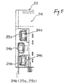
- the second connector 24 is constituted by a 3-pin connector and has connecting pins 24a, 24b and 24c for conversion which are arranged at regular intervals and penetrate through the back face of the body 22 in a longitudinal direction as shown in Figs. 1 and 5.
- the second connector 24 has the top (first) connecting pin 24a connected to a fourth pin (A4) 23e of the connector 23b for an A-part of the first connector 23, and the third connecting pin 24c connected to a seventh pin (A7) 23d of the connector 23b for an A-part of the first connector 23.
- the second connector 24 has the second connecting pin 24b penetrating through the back face of the body 12 in the longitudinal direction, extended sideward (downward in Fig. 1) and connected to a BUP output terminal of a circuit formed on the main print circuit board 21 at the user side (see Fig. 8), for example.
- the contact pin 23c and the connecting pins 24a, 24b and 24c are formed of a conductor, and their ends extended rearward are protruded rearward from the back face of the body 22 excluding the contact pin 24b and are inserted in through holes provided on the sub-print circuit board 31 and can be electrically connected at lower edges of the through holes by soldering during mounting and the other ends are protruded forward in the body 22 such that contacts can abut when the corresponding connecting terminals 25a and 25b and the auto fuse 30 (see Fig. 5) are to be connected.
- one of ends of the connecting pin 24b penetrates through the back face of the body 22 in the longitudinal direction, is extended sideward (downward in Fig. 1), is inserted in a through hole provided on the main print circuit board 21 and can be electrically connected at a lower edge of the through hole by soldering and the other end thereof is protruded upward in the body 22 such that a contact 32 or 33 of the corresponding auto fuse 30 can abut thereon (see Fig. 8).
- connecting terminals 25a and 25b acting as normally-closed contacts are provided adjacently to the first and third connecting pins 24a and 24c in the second connector 24.
- the connecting terminals 25a and 25b are formed of an elastic member and have almost inverted U-shaped sections as shown in Fig. 5.
- Each of the connecting terminals 25a and 25b has one of ends extended rearward and sideward (downward in Fig. 1) through the body 20 and connected to the main print circuit board 21, and the other end provided in contact with each of the connecting pins 24a and 24c with elasticity.
- each of the connecting terminals 25a and 25b is protruded into a hollow portion 24d of the second connector 24 and is pressed against the elasticity of each of the connecting terminals 25a and 25b through the body of the auto fuse 30 entering the hollow portion 24d and is separated from each of the connecting pins 24a and 24c of the second connector 24 when the auto fuse 30 is attached to the second connector 24 as will be described below.
- each of the connecting terminals 25a and 25b is protruded downward from the back face of the body 22, is inserted in the through hole provided on the main print circuit board 21 and is electrically connected at the lower edge of the through hole by soldering during the mounting.
- the end is connected to the connecting terminal for ACC of a circuit provided on the main print circuit board 21, for example.
- Fig. 7 shows the auto fuse 30 which is attached to the second connector 24 to selectively short-circuit the connecting pin.
- the auto fuse 30 itself has a known structure and has been put on the market, and is constituted by a body 31 which can be inserted into the hollow portion 24d opened upward in the second connector 24 and two contacts 32 and 33 protruded downward to abut on the upper end of the connecting pin 24a for conversion of the second connector 24 in the body 31.
- the body 31 is formed of an insulating material and presses one of the ends of each of the connecting terminals 25a and 25b protruded into the hollow portion 24d and separates the end from each of the connecting pins 24a and 24c when the body 31 is inserted into the hollow portion 24d of the second connector 24.
- the contacts 32 and 33 of the auto fuse 30 are electrically connected to each other or are constituted integrally.
- the auto fuse 30 is selectively inserted into the hollow portion 24d of the second connector 24 and is attached thereto such that the two contacts 32 and 33 are engaged with the first connecting pin 24a and the second connecting pin 24b of the second connector 24 or with the second connecting pin 24b and the third connecting pin 24c of the second connector 24.
- the electric connector 20 according to the embodiment of the invention has a different structure in the following respect.
- the sub-print circuit board 31 is provided opposite to the back face of the body 22.
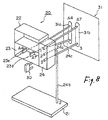
- the sub-print circuit board 31 is a printed board, and includes a through hole for accepting the contact pin 23c and the connecting pins 24a and 24c protruded from the back face of the body 22 and a conductive pattern for properly connecting the through holes, in particular, a connecting pattern 31a for connecting the first connecting pin 24a to the fourth pin (A4) 23e of the connector 23b for an A-part of the first connector 23 and a connecting pattern 31b for connecting the third connecting pin 24c to the seventh pin (A7) 23d of the connector 23b for an A-part of the first connector 23 (other wiring patterns are omitted) as shown in Fig. 8.
- the electric connector 20 has the above-mentioned structure, and the back face of the body 22 is mounted on the upper face of the main print circuit board 21 such that the lower ends of the contact pin 23c and the connecting pins 24a and 24c are inserted into the through holes (not shown) provided on the sub-print circuit board 31 respectively during assembly. Then, the lower ends of the contact pin 23c and the connecting pins 24a and 24c are soldered at the lower ends of the through holes of the sub-print circuit board 31 by solder dipping, for example and can be electrically connected to the circuit provided on the lower face of the main print circuit board 21.
- the connecting terminals of the connectors 23a and 23b of the first connector 23 are connected to the connecting terminals of the circuit provided on the sub-print circuit board 31 respectively, and the fourth pin 23e and the seventh pin 23d of the connector 23b are connected to the first connecting pin 24a and the third connecting pin 24c of the second connector 24 through the connecting patterns 31a and 31b formed on the sub-print circuit board 31 respectively.
- the body 22 is mounted on the main print circuit board 21 such that the lower ends of the connecting pin 24b and the connecting terminals 25a and 25b are inserted into the through holes (not shown) provided on the main print circuit board 21, respectively. Then, the lower ends of the contact pin 24b and the connecting terminals 25a and 25b are soldered at the lower ends of the through holes of the main print circuit board 21 by solder dipping, for example, and can be electrically connected to the circuit provided on the lower face of the main print circuit board 21.
- the second connecting pin 24b of the second connector 24 is connected to the BUP output terminal of the circuit provided on the main print circuit board 21 at the user side in a car audio system.
- each of the connecting terminals 25a and 25b is connected to the connecting terminal for ACC of the circuit provided on the main print circuit board 21, for example.
- the auto fuse 30 is selectively attached to the second connector 24 as described above corresponding to a wiring specification of a connecting socket on the body side to be connected to the first connector 23 of the electric connector 20 which is determined by automobile manufactures.
- the BUP and the ACC are selectively connected to the fourth pin 23e or the seventh pin 23d of the connector 23b for an A-part of the first connector 23 depending on a position where the auto fuse 30 is to be attached.
- the body 32 of the auto fuse 30 when the body 32 of the auto fuse 30 is inserted into the hollow portion 24d of the second converting connector 24 and the auto fuse 30 is attached to the second connector 24 such that the two contacts 32 and 33 of the auto fuse 30 are engaged with the first and second connecting pins 24a and 24b of the second connector 24, the body 32 of the auto fuse 30 presses the other end of the connecting terminal 25a to be separated from the first connecting pin 24a and short-circuits the first connecting pin 24a and the second connecting pin 24b of the second connector 24 through the two contacts 32 and 33 of the auto fuse 30. At this time, the connecting terminal 25b is not pressed by the body 32 of the auto fuse 30 and is therefore maintained in contact with the third connecting pin 24c.
- the ACC is connected to the seventh pin 23d of the connector 23b for an A-part of the first connector 23 through the connecting terminal 25b and the BUP output is connected from the connecting 24b to the fourth pin 23e of the connector 23b for an A-part of the first connector 23 through the auto fuse 30.
- the body 32 of the auto fuse 30 when the body 32 of the auto fuse 30 is inserted into the hollow portion 24d of the second converting connector 24 and the auto fuse 30 is attached to the second connector 24 such that the two contacts 32 and 33 of the auto fuse 30 are engaged with the second connecting pin 24b and the third connecting pin 24c of the second connector 20, the body 32 of the auto fuse 30 presses the other end of the connecting terminal 25b to be separated from the third connecting pin 24c and short-circuits the second connecting pin 24b and the third connecting pin 24c of the second connector 24 through the two contacts 32 and 33 of the auto fuse 30. At this time, the connecting terminal 25a is not pressed by the body 32 of the auto fuse 30 and is therefore maintained in contact with the first connecting pin 24a.
- the BUP output is connected to the seventh pin 23d of the connector 23b for an A-part of the first connector 23 through the auto fuse 30 and the ACC is connected to the fourth pin 23e of the connector 23b for an A-part of the first connector 23 through the connecting terminal 25a.
- the fourth pin or seventh pin of the connector 23b for an A-part of the first connector 23 is connected to the first connecting pin 24a or the third connecting pin 24c of the second connector 24 through the connecting patterns 31a and 31b formed on the sub-print circuit board 31, respectively. Therefore, a connection is not carried out through the connecting pattern provided on the print circuit board at the user side differently from the conventional art. Consequently, it is not necessary to provide the spaces for mounting the connecting pins 24a and 24c on the print circuit board at the user side and the conductive patterns.
- the main print circuit board 21 at the user side can be small-sized and can be carried out at a low cost.
- the width of the conductive pattern constituting the circuit on the main print circuit board 21 at the user side can be increased.
- the two signal terminals to be switched in the first connector and the first and third connecting pins of the second connector are mounted on the sub-print circuit board including the connecting patterns for mutual connection. Consequently, it is not necessary to provide mounting spaces and through holes for the signal terminals and the connecting pins and a connecting pattern for mutually connecting them on the main print circuit board at the user side. Accordingly, it is not necessary to consider the mounting spaces, the through holes and the connecting patterns on the main print circuit board at the user side during the design of a circuit pattern thereof. Thus, the degree of freedom of the design can be increased and the circuit pattern can also be widened so that reliability can be enhanced.
- the signal terminals and the connecting pins are previously mounted on the sub-print circuit board. Consequently, it is possible to simplify a work for mounting the electric connector on the main print circuit board at the user side.
Landscapes
- Coupling Device And Connection With Printed Circuit (AREA)
Abstract
Description
- The present invention relates to an electric connector for connecting an audio system for automobiles and more particularly to an electric connector having an ISO standard for connecting various signal lines together.
- Conventionally, such an electric connector is constituted as shown in Fig. 9, for example.
- In Fig. 9, an electric connector 1 is mounted on a
print circuit board 2 of an audio system for automobiles through solder dipping, for example, and is used for connecting various signal lines, that is, a power supply, an audio signal, and lines for ACC (Accessory), BUP (Back Up) and a speaker to the body side. - A
connector 3 for a speaker connected to the speaker on the body side and aconnector 4 for a signal line connected to the power supply on the body side are connected to the electric connector 1 thus mounted on theprint circuit board 2. Consequently, an on-vehicle speaker is connected, and furthermore, power is supplied to the audio system for automobiles which is provided on theprint circuit board 2. Moreover, the audio signal is output to an apparatus which is not shown. - Such an electric connector having the ISO standard has widely been employed in automobile manufacturers in various countries, particularly, Europe. The connector is unified to be common and has various wirings depending on the automobile manufactures in some cases. For example, the electric connector having the ISO standard is provided with ACC (accessory) and BUP (back up) wirings which are reverse to each other in some cases.
- In order to cope with the difference between the wirings, conventionally, there has been employed a method of interposing an
adaptor 5 for circuit conversion between the electric connector 1 and theconnector 4 for a signal line as shown in Fig. 10. - In the
adaptor 5 for circuit conversion, a connecting terminal which is removable in a middle portion is provided onsignal lines 5a and 5b related to the ACC and the BUP. By rearranging the connecting terminal if necessary, the ACC and the BUP can be connected correctly. - However, if such an
adaptor 5 for circuit conversion is used to correspond to automobile manufactures having different wirings, the number of parts is increased so that a cost is increased and a work for rearranging the connecting terminals is required, resulting in a deterioration in workability. - On the other hand, there has also been known an electric connector capable of easily replacing wirings as shown in Figs. 11 to 13, for example.
- In Figs. 11 and 13, an
electric connector 10 is constituted by abody 12 formed of a mold resin which is mounted on a main print circuit board 11 (theprint circuit board 2 in Fig. 10) at the user side, afirst connector 13 including two 8-pin connectors body 12, asecond connector 14 including a 3-pin connector and anauto fuse 16 attached to the second connector 14 (see Figs. 11, 14 and 5). - The
first connector 13 includes the two 8-pin connectors connector 13a constitutes a connector for a speaker (a B-part) and theconnector 13b constitutes a connector for an A-part. - Each of the
connectors contact pin 13c penetrating through the back face of thebody 12 in a longitudinal direction as shown in Fig. 12. An end of thecontact pin 13c which is extended rearward is protruded longitudinally from below thebody 12 and sideward (downward in Fig. 11). - The
second connector 14 is constituted by the 3-pin connector and has connectingpins body 12 in a longitudinal direction and are extended sideward (rearward in Fig. 11) as shown in Figs. 11 and 12. - As shown in Fig. 13, the
second connector 14 has the top (first) connecting pin 14a connected to a fourth pin (A4) 13e of theconnector 13b for an A-part of thefirst connector 13, and the third connectingpin 14c connected to a seventh pin (A7) 13d of theconnector 13b for an A-part of thefirst connector 13. This connection is carried out through a conductive pattern formed on the main print circuit board 11 at the user side. - Furthermore, the
second connector 14 has the second connectingpin 14b connected to a BUP output terminal of a circuit, for example, and a signal is output to the print circuit board at the user side. - The
contact pins body 12 such that contacts can be opened when the corresponding connectingterminals - On the other hand, the connecting
terminals pins 14a and 14c in thesecond connector 14. - The connecting
terminals terminals body 12 and the other end provided in contact with each of the connectingpins 14a and 14c with elasticity. - The other end of each of the connecting
terminals second connector 14 and is pressed against the elasticity of each of the connectingterminals auto fuse 16 entering the hollow portion 14d and is separated from each of the connectingpins 14a and 14c of thesecond connector 14 when theauto fuse 16 is attached to thesecond connector 14 as will be described below. - Moreover, one of the ends of each of the connecting
terminals body 12, is inserted in the through hole provided on the main print circuit board 11 at the user side and is electrically connected at the lower edge of the through hole by soldering during the mounting. Thus, the end is connected to the connecting terminal for ACC of a circuit provided on the main print circuit board 11, for example. - Fig. 14 shows the
auto fuse 16 which is attached to thesecond connector 14 to selectively short-circuit the connecting pin. - The
auto fuse 16 itself has a known structure and has been put on the market, and is constituted by abody 16a which can be inserted into the hollow portion 14d opened upward in thesecond connector 14 and twocontacts second connector 14 in the body 16 (see Fig. 14). - The
body 16a is formed of an insulating material, presses one of the ends of each of the connectingterminals pins 14a and 14c when thebody 16a is inserted into the hollow portion 14d of thesecond connector 14. - Moreover, the
contacts auto fuse 16 are electrically connected to each other in thebody 16a or are constituted integrally. - Consequently, the
auto fuse 16 is selectively inserted into the hollow portion 14d of thesecond connector 14 and is attached thereto such that the twocontacts pin 14b of thesecond connector 14 or with the second connectingpin 14b and the third connectingpin 14c of thesecond connector 14. - According to the
electric connector 10 having such a structure, the bottom face of thebody 12 is mounted on the upper face of the main print circuit board 11 such that the lower ends of thecontact pins pins contact pins pins - Consequently, the connecting terminals of the
connectors first connector 13 are connected to the connecting terminals of the circuit provided on the main print circuit board 11 except for the fourth and seventh pins of theconnector 13b, and thefourth pin 13e and theseventh pin 13d of theconnector 13b are connected to the first connecting pin 14a and the third connectingpin 14c of thesecond connector 14 throughconductive patterns 11a and 11b formed on the main print circuit board 11 as shown in Fig. 15. - Furthermore, the second connecting
pin 14b of thesecond connector 14 is connected to the BUP output terminal of the circuit provided on a print circuit board (not shown) of a car audio system. - Moreover, one of the ends of each of the connecting
terminals - Then, the
auto fuse 16 is selectively attached to thesecond connector 14 as described above corresponding to a wiring specification of a connecting socket on the body side to be connected to thefirst connector 13 of theelectric connector 10 which is determined by automobile manufactures. - Consequently, the BUP and the ACC are selectively connected to the
fourth pin 13e or theseventh pin 13d of theconnector 13b for an A-part of thefirst connector 13 depending on a position where theauto fuse 16 is to be attached. - More specifically, when the
body 16a of theauto fuse 16 is inserted into the hollow portion 14d of the second convertingconnector 14 such that the twocontacts auto fuse 16 are engaged with the first and second connectingpins 14a and 14b of thesecond connector 14, thebody 16a of theauto fuse 16 presses the other end of the connectingterminal 15a to be separated from the first connecting pin 14a and short-circuits the first connecting pin 14a and the second connectingpin 14b of thesecond connector 14 through the twocontacts auto fuse 16. At this time, the connectingterminal 15b is not pressed by thebody 16a of theauto fuse 16 and is therefore maintained in contact with the third connectingpin 14c. - Consequently, the ACC is connected to the
seventh pin 13d of theconnector 13b for an A-part of thefirst connector 13 through the connectingterminal 15b and the BUP output is connected from the connectingpin 14b to thefourth pin 13e of theconnector 13b for an A-part of thefirst connector 13 through theauto fuse 16. - On the other hand, when the
body 16a of theauto fuse 16 is inserted into the hollow portion 14d of the second convertingconnector 14 such that the twocontacts auto fuse 16 are engaged with the second connectingpin 14b and the third connectingpin 14c of thesecond connector 20, thebody 16a of theauto fuse 16 presses the other end of the connectingterminal 15b to be separated from the third connectingpin 14c and short-circuits the second connectingpin 14b and the third connectingpin 14c of thesecond connector 14 through the twocontacts auto fuse 16. At this time, the connectingterminal 15a is not pressed by thebody 16a of theauto fuse 16 and is therefore maintained in contact with the first connecting pin 14a. - Consequently, the BUP output is connected to the
seventh pin 13d of theconnector 13b for an A-part of thefirst connector 13 through theauto fuse 16 and the ACC is connected to thefourth pin 13e of theconnector 13b for an A-part of thefirst connector 13 through theconnecting terminal 15a. - In the
electric connector 10 thus mounted on the main print circuit board 11, the connecting socket on the body side is inserted into each of theconnectors first connector 13. Consequently, a desirable electrical connection can be carried out. - More specifically, the fourth pin or the seventh pin of the
connector 13b for an A-part of thefirst connector 13 can properly be set to the BUP and the ACC corresponding to the automobile manufactures through the position where theauto fuse 16 is to be attached to thesecond connector 14. Accordingly, the connecting plug on the body side can be directly connected to thefirst connector 13 of theelectric connector 10 without using an adaptor for circuit conversion corresponding to all automobile manufactures having different wirings. - In the
electric connector 10 having such a structure, however, thefourth pin 13e and theseventh pin 13d of theconnector 13b for an A-part of thefirst connector 13 and thecontact pins 14a and 14c of thesecond connector 14 are mounted on the main print circuit board 11 at the user side and are electrically connected to each other through the connecting pattern formed on the main print circuit board 11 as shown in Fig. 15. - Therefore, a back-up current supplied from an automobile is output from the
fourth pin 13e or theseventh pin 13d of theconnector 13b for an A-part of thefirst connector 13 to the main print circuit board 11 at the user side, is output to thecontact pin 14a or 14c of thesecond connector 14 through the connecting pattern formed on the main print circuit board 11 at the user side, and is further output from the connectingterminal auto fuse 16 again. - Accordingly, the main print circuit board 11 at the user side should be provided with mounting spaces and through holes for the
fourth pin 13e andseventh pin 13d of theconnector 13b for an A-part of thefirst connector 13 and thecontact pins 14a and 14c of thesecond connector 14 and requires the connecting pattern for mutually connecting the through holes. Therefore, there has been a problem in that the size of the main print circuit board 11 is increased and the design of a circuit pattern in the main print circuit board 11 is restricted. - In consideration of the above-mentioned respects, it is an object of the present invention to provide an electric connector having a simple and inexpensive structure in which a wiring between a first connector and a second connector can be carried out without passing through a main print circuit board at the user side.
- In order to achieve the object, the present invention provides an electric connector (20) comprising a first connector (23) including a plurality of signal terminals and mounted on a main print circuit board (21), a second connector (24) including three connecting pins (24a), (24b) and (24c) arranged at regular intervals, the first and third connecting pins (24a) and (24c) being connected to two signal terminals (23d) and (23e) to be switched in the first connector (23) and a signal to be switched being supplied to the first arid third connecting pins (24a) and (24c) through normally-closed contacts (25a) and (25b) and directly to the second connecting pin (24b), and an auto fuse (30) including two contacts (32) and (33) arranged at a regular interval to be selectively engaged with two connecting pins on one of sides or the other side of the second connector (24), the two contacts being electrically connected to each other, and serving to open the normally-closed contacts (25a) and (25b) coming in contact with the first or third connecting pin (24a) or (24c) when being engaged with the second connector (24), wherein the two signal terminals (23d) and (23e) to be switched in the first connector (23) and the first and third connecting pins (24a) and (24c) of the second connector (24) are mounted on a sub-print circuit board (31) including connecting patterns (31a) and (31b) to be connected to each other.
- According to the structure, one of the signal lines to be switched (a power supply, an audio signal and a control signal) is connected to the first and third connecting pins (24a) and (24c) of the second connector (24) through the normally-closed contacts (25a) and (25b) and the other signal line is directly connected to the second connecting pin (24b) of the second connector (24), and the first and third connecting pins (24a) and (24c) of the second connector (24) are connected to the corresponding signal terminals of the first connector (23), respectively.
- When the auto fuse (30) is attached to the second connector (24) such that the two contacts (32) and (33) of the auto fuse (30) are engaged with the first and second connecting pins (24a) and (24c) of the second connector (24), the first and second connecting pins (24a) and (24c) of the second connector (24) are short-circuited by the auto fuse (30) and the normally-closed contact (25a) provided in contact with the first connecting pin (24a) is separated from the first connecting pin (24a) through the body of the auto fuse (30).
- Consequently, one of the signal lines to be switched is connected through the normally-closed contact (25b) to the signal terminal (23d) of the first connector (23) connected to the third connecting pin (24c) of the second connector (24), and the other signal line to be switched is connected through the auto fuse (30) from the second connecting pin (24b) of the second connector (24) to the signal terminal (23e) of the first connector (23) connected to the first connecting pin (24a) of the second connector (24).
- On the other hand, when the auto fuse (30) is attached to the second connector (24) such that the two contacts (32) and (33) of the auto fuse (30) are engaged with the second and third connecting pins (24b) and (24c) of the second connector (24), the second and third connecting pins (24b) and (24c) of the second connector (24) are short-circuited by the auto fuse (30) and the normally-closed contact (25b) provided in contact with the third connecting pin (24c) is separated from the third connecting pin (24c) through the body (31) of the auto fuse (30).
- Consequently, one of the signal lines to be switched is connected through the normally-closed contact (25a) to the signal terminal (23e) of the first connector (23) connected to the first connecting pin (24a) of the second connector (24), and the other signal line to be switched is connected through the auto fuse (30) from the second connecting pin (24b) of the second connector (24) to the signal terminal (23d) of the first connector (23) connected to the third connecting pin (24c) of the second connector (24).
- Accordingly, in the case in which the two signal lines are replaced, the position where the auto fuse (30) is to be attached to the second connector (24) is shifted. Thus, it is possible to easily take countermeasures for a difference in the wiring at the corresponding connector side which is to be connected to the first connector (23).
- In this case, the two signal terminals (23d) and (23e) to be switched in the first connector (23) and the first and third connecting pins (24) and (24c) of the second connector (24) are mounted on the sub-print circuit board (31) including the connecting patterns (31a) and (31b) to be connected to each other. Consequently, it is not necessary to provide, on the main print circuit board (21) at the user side, the mounting spaces and through holes for the signal terminals and the connecting pins and the connecting patterns for mutually connecting them. Referring to the main print circuit board (21) at the user side, accordingly, it is not necessary to consider the mounting spaces, the through holes and the connecting patterns during the design of a circuit pattern. Therefore, the degree of freedom of a design can be increased and the circuit pattern can be widened so that reliability can be enhanced.
- Furthermore, the signal terminals (23d) and (23e) and the connecting pins (24a) and (24c) are previously mounted on the sub-print circuit board (31). Consequently, it is possible to simplify a work for mounting the electric connector (20) on the main print circuit board (21) at the user side.
- The designations in the parentheses are attached for easy understanding as an example and are not restricted.
-
- Fig. 1 is a front view showing an electric connector according to an embodiment of the invention,
- Fig. 2 is a bottom view showing the electric connector of Fig. 1,
- Fig. 3 is a right side view showing the electric connector of Fig. 1,
- Fig. 4 is a sectional view taken along the line Y1 - Y1 in the electric connector of Fig. 1,
- Fig. 5 is a rear view showing a main part in the electric connector of Fig. 1,
- Fig. 6 is a schematic view showing a sate in which a first connector and a second connector in the electric connector of Fig. 1 are connected,
- Fig. 7 is a front view showing an auto fuse to be connected to the second connector in the electric connector of Fig. 1,
- Fig. 8 is a schematic perspective view showing a state in which the electric connector of Fig. 1 is connected to a sub-print circuit board and a main print circuit board,
- Fig. 9 is a schematic view showing a state in which a conventional electric connector is used as an example,
- Fig. 10 is a schematic view showing the state of use in which signal lines are replaced through the electric connector of Fig. 9,
- Fig. 11 is a front view showing the conventional electric connector according to another example,
- Fig. 12 is a sectional view taken along the line X - X in the electric connector of Fig. 11,
- Fig. 13 is a schematic enlarged view showing a state in which a first connector and a second connector in the electric connector of Fig. 11 are connected,
- Fig. 14 is a front view showing an auto fuse to be used in the electric connector of Fig. 11, and
- Fig. 15 is a schematic perspective view showing a state in which the electric connector of Fig. 11 is connected to a print circuit board at the user side.
-
- The invention will be described in detail based on an embodiment with reference to the drawings.
- Figs. 1 to 8 show the structure of an electric connector according to the embodiment of the invention.
- In Figs. 1 to 3, an
electric connector 20 is a connector for connecting an audio system for automobiles having an ISO standard (ISO 30487 - 1) and is constituted by abody 22 to be mounted on a mainprint circuit board 21 at the user side, afirst connector 23 including two 8-pin connectors body 22, asecond connector 24 including a 3-pin connector and an auto fuse 30 (see Fig. 7) to be attached to thesecond connector 24, and furthermore, asub-print circuit board 31 fixed to a bottom face of the body 22 (see Fig. 8). - The
body 22 is formed of a mold resin, for example, and the bottom face thereof (a lower face in Fig. 1) comes in contact with an upper face of the mainprint circuit board 21 during the work for mounting the print circuit board. - The
first connector 23 includes the two 8-pin connectors connector 23a constitutes a connector for a speaker (a B part) and theconnector 23b constitutes a connector for an A-part. - Each of the
connectors contact pin 23c connected to thesub-print circuit board 31 through the back face of thebody 22 in a longitudinal direction as shown in Fig. 4. (In Fig. 1, theconnector 23b has seven contact pins (indicated as A1 to A8)). - The
second connector 24 is constituted by a 3-pin connector and has connectingpins body 22 in a longitudinal direction as shown in Figs. 1 and 5. - As shown in Fig. 6, the
second connector 24 has the top (first) connecting pin 24a connected to a fourth pin (A4) 23e of theconnector 23b for an A-part of thefirst connector 23, and the third connectingpin 24c connected to a seventh pin (A7) 23d of theconnector 23b for an A-part of thefirst connector 23. - Furthermore, the
second connector 24 has the second connectingpin 24b penetrating through the back face of thebody 12 in the longitudinal direction, extended sideward (downward in Fig. 1) and connected to a BUP output terminal of a circuit formed on the mainprint circuit board 21 at the user side (see Fig. 8), for example. - The
contact pin 23c and the connectingpins body 22 excluding thecontact pin 24b and are inserted in through holes provided on thesub-print circuit board 31 and can be electrically connected at lower edges of the through holes by soldering during mounting and the other ends are protruded forward in thebody 22 such that contacts can abut when the corresponding connectingterminals - Moreover, one of ends of the connecting
pin 24b penetrates through the back face of thebody 22 in the longitudinal direction, is extended sideward (downward in Fig. 1), is inserted in a through hole provided on the mainprint circuit board 21 and can be electrically connected at a lower edge of the through hole by soldering and the other end thereof is protruded upward in thebody 22 such that acontact corresponding auto fuse 30 can abut thereon (see Fig. 8). - On the other hand, the connecting
terminals pins 24a and 24c in thesecond connector 24. - The connecting
terminals terminals body 20 and connected to the mainprint circuit board 21, and the other end provided in contact with each of the connectingpins 24a and 24c with elasticity. - The other end of each of the connecting
terminals second connector 24 and is pressed against the elasticity of each of the connectingterminals auto fuse 30 entering the hollow portion 24d and is separated from each of the connectingpins 24a and 24c of thesecond connector 24 when theauto fuse 30 is attached to thesecond connector 24 as will be described below. - Moreover, one of the ends of each of the connecting
terminals body 22, is inserted in the through hole provided on the mainprint circuit board 21 and is electrically connected at the lower edge of the through hole by soldering during the mounting. Thus, the end is connected to the connecting terminal for ACC of a circuit provided on the mainprint circuit board 21, for example. - Fig. 7 shows the
auto fuse 30 which is attached to thesecond connector 24 to selectively short-circuit the connecting pin. - The
auto fuse 30 itself has a known structure and has been put on the market, and is constituted by abody 31 which can be inserted into the hollow portion 24d opened upward in thesecond connector 24 and twocontacts second connector 24 in thebody 31. - The
body 31 is formed of an insulating material and presses one of the ends of each of the connectingterminals pins 24a and 24c when thebody 31 is inserted into the hollow portion 24d of thesecond connector 24. - Moreover, the
contacts auto fuse 30 are electrically connected to each other or are constituted integrally. - Consequently, the
auto fuse 30 is selectively inserted into the hollow portion 24d of thesecond connector 24 and is attached thereto such that the twocontacts pin 24b of thesecond connector 24 or with the second connectingpin 24b and the third connectingpin 24c of thesecond connector 24. - Although the structure is almost the same as that of the conventional
electric connector 10 shown in Figs. 11 to 15, theelectric connector 20 according to the embodiment of the invention has a different structure in the following respect. - More specifically, the
sub-print circuit board 31 is provided opposite to the back face of thebody 22. - The
sub-print circuit board 31 is a printed board, and includes a through hole for accepting thecontact pin 23c and the connectingpins 24a and 24c protruded from the back face of thebody 22 and a conductive pattern for properly connecting the through holes, in particular, a connecting pattern 31a for connecting the first connecting pin 24a to the fourth pin (A4) 23e of theconnector 23b for an A-part of thefirst connector 23 and a connecting pattern 31b for connecting the third connectingpin 24c to the seventh pin (A7) 23d of theconnector 23b for an A-part of the first connector 23 (other wiring patterns are omitted) as shown in Fig. 8. - The
electric connector 20 according to the embodiment of the invention has the above-mentioned structure, and the back face of thebody 22 is mounted on the upper face of the mainprint circuit board 21 such that the lower ends of thecontact pin 23c and the connectingpins 24a and 24c are inserted into the through holes (not shown) provided on thesub-print circuit board 31 respectively during assembly. Then, the lower ends of thecontact pin 23c and the connectingpins 24a and 24c are soldered at the lower ends of the through holes of thesub-print circuit board 31 by solder dipping, for example and can be electrically connected to the circuit provided on the lower face of the mainprint circuit board 21. - Consequently, the connecting terminals of the
connectors first connector 23 are connected to the connecting terminals of the circuit provided on thesub-print circuit board 31 respectively, and thefourth pin 23e and theseventh pin 23d of theconnector 23b are connected to the first connecting pin 24a and the third connectingpin 24c of thesecond connector 24 through the connecting patterns 31a and 31b formed on thesub-print circuit board 31 respectively. - When the
electric connector 20 having such a structure is to be mounted on the mainprint circuit board 21, thebody 22 is mounted on the mainprint circuit board 21 such that the lower ends of the connectingpin 24b and the connectingterminals print circuit board 21, respectively. Then, the lower ends of thecontact pin 24b and the connectingterminals print circuit board 21 by solder dipping, for example, and can be electrically connected to the circuit provided on the lower face of the mainprint circuit board 21. - Consequently, the second connecting
pin 24b of thesecond connector 24 is connected to the BUP output terminal of the circuit provided on the mainprint circuit board 21 at the user side in a car audio system. - Moreover, one of the ends of each of the connecting
terminals print circuit board 21, for example. - Then, the
auto fuse 30 is selectively attached to thesecond connector 24 as described above corresponding to a wiring specification of a connecting socket on the body side to be connected to thefirst connector 23 of theelectric connector 20 which is determined by automobile manufactures. - Consequently, the BUP and the ACC are selectively connected to the
fourth pin 23e or theseventh pin 23d of theconnector 23b for an A-part of thefirst connector 23 depending on a position where theauto fuse 30 is to be attached. - More specifically, when the
body 32 of theauto fuse 30 is inserted into the hollow portion 24d of the second convertingconnector 24 and theauto fuse 30 is attached to thesecond connector 24 such that the twocontacts auto fuse 30 are engaged with the first and second connectingpins 24a and 24b of thesecond connector 24, thebody 32 of theauto fuse 30 presses the other end of the connecting terminal 25a to be separated from the first connecting pin 24a and short-circuits the first connecting pin 24a and the second connectingpin 24b of thesecond connector 24 through the twocontacts auto fuse 30. At this time, the connecting terminal 25b is not pressed by thebody 32 of theauto fuse 30 and is therefore maintained in contact with the third connectingpin 24c. - Consequently, the ACC is connected to the
seventh pin 23d of theconnector 23b for an A-part of thefirst connector 23 through the connecting terminal 25b and the BUP output is connected from the connecting 24b to thefourth pin 23e of theconnector 23b for an A-part of thefirst connector 23 through theauto fuse 30. - On the other hand, when the
body 32 of theauto fuse 30 is inserted into the hollow portion 24d of the second convertingconnector 24 and theauto fuse 30 is attached to thesecond connector 24 such that the twocontacts auto fuse 30 are engaged with the second connectingpin 24b and the third connectingpin 24c of thesecond connector 20, thebody 32 of theauto fuse 30 presses the other end of the connecting terminal 25b to be separated from the third connectingpin 24c and short-circuits the second connectingpin 24b and the third connectingpin 24c of thesecond connector 24 through the twocontacts auto fuse 30. At this time, the connecting terminal 25a is not pressed by thebody 32 of theauto fuse 30 and is therefore maintained in contact with the first connecting pin 24a. - Consequently, the BUP output is connected to the
seventh pin 23d of theconnector 23b for an A-part of thefirst connector 23 through theauto fuse 30 and the ACC is connected to thefourth pin 23e of theconnector 23b for an A-part of thefirst connector 23 through the connecting terminal 25a. - Thus, in the
electric connector 20 mounted on the mainprint circuit board 21, a connecting socket on the body side is inserted into each of theconnectors first connector 23. Consequently, a desirable electrical connection can be carried out. - The fourth pin or seventh pin of the
connector 23b for an A-part of thefirst connector 23 is connected to the first connecting pin 24a or the third connectingpin 24c of thesecond connector 24 through the connecting patterns 31a and 31b formed on thesub-print circuit board 31, respectively. Therefore, a connection is not carried out through the connecting pattern provided on the print circuit board at the user side differently from the conventional art. Consequently, it is not necessary to provide the spaces for mounting the connectingpins 24a and 24c on the print circuit board at the user side and the conductive patterns. - Accordingly, only the connecting
pin 24 and the connectingterminals print circuit board 21 at the user side are finally mounted on the mainprint circuit board 21 at the user side. Thus, the mainprint circuit board 21 at the user side can be small-sized and can be carried out at a low cost. In addition, in the case in which a print circuit board having the same size is to be used, the width of the conductive pattern constituting the circuit on the mainprint circuit board 21 at the user side can be increased. - While the connector having the ISO standard for connecting the audio system for automobiles has been described in the embodiment, it is apparent that the invention can be applied to an electric connector which requires replacement of wirings in various apparatuses.
- As described above, according to the invention, the two signal terminals to be switched in the first connector and the first and third connecting pins of the second connector are mounted on the sub-print circuit board including the connecting patterns for mutual connection. Consequently, it is not necessary to provide mounting spaces and through holes for the signal terminals and the connecting pins and a connecting pattern for mutually connecting them on the main print circuit board at the user side. Accordingly, it is not necessary to consider the mounting spaces, the through holes and the connecting patterns on the main print circuit board at the user side during the design of a circuit pattern thereof. Thus, the degree of freedom of the design can be increased and the circuit pattern can also be widened so that reliability can be enhanced.
- Furthermore, the signal terminals and the connecting pins are previously mounted on the sub-print circuit board. Consequently, it is possible to simplify a work for mounting the electric connector on the main print circuit board at the user side.
- According to the invention, thus, it is possible to provide a very excellent electric connector having a simple and inexpensive structure in which a wiring between a first connector and a second connector is carried out without passing through a main print circuit board at the user side.
Claims (2)
- An electric connector comprising:a first connector including a plurality of signal terminals and mounted on a main print circuit board;a second connector including three connecting pins arranged at regular intervals, the first and third connecting pins being connected to two signal terminals to be switched in the first connector and a signal to be switched being supplied to the first and third connecting pins through a normally-closed contact and directly to the second connecting pin; andan auto fuse including two contacts arranged at a regular interval to be selectively engaged with two connecting pins on one of sides or the other side of the second connector, the two contacts being electrically connected to each other, and serving to open the normally-closed contact coming in contact with the first or third connecting pin when being engaged with the second connector.a sub-print circuit board for connecting first connector and second connector.
- An electric connector as claimed in claim 1, wherein the two signal terminals to be switched in the first connector and the first and third connecting pins of the second connector are mounted on a sub-print circuit board including connecting patterns to be connected to each other.
Applications Claiming Priority (2)
| Application Number | Priority Date | Filing Date | Title |
|---|---|---|---|
| JP31050699 | 1999-11-01 | ||
| JP31050699A JP2001135438A (en) | 1999-11-01 | 1999-11-01 | Electrical connector |
Publications (2)
| Publication Number | Publication Date |
|---|---|
| EP1096621A1 true EP1096621A1 (en) | 2001-05-02 |
| EP1096621B1 EP1096621B1 (en) | 2007-02-07 |
Family
ID=18006055
Family Applications (1)
| Application Number | Title | Priority Date | Filing Date |
|---|---|---|---|
| EP00123864A Expired - Lifetime EP1096621B1 (en) | 1999-11-01 | 2000-11-02 | Electric connector |
Country Status (3)
| Country | Link |
|---|---|
| EP (1) | EP1096621B1 (en) |
| JP (1) | JP2001135438A (en) |
| DE (1) | DE60033255T2 (en) |
Citations (4)
| Publication number | Priority date | Publication date | Assignee | Title |
|---|---|---|---|---|
| US3957333A (en) * | 1974-11-01 | 1976-05-18 | Dana Corporation | Universal control system interface |
| EP0520284A2 (en) * | 1991-06-25 | 1992-12-30 | Yazaki Corporation | An electric junction box |
| US5443389A (en) * | 1993-07-16 | 1995-08-22 | Hughes; Michael T. | Unified connector interface |
| EP0951103A2 (en) * | 1998-04-16 | 1999-10-20 | Mitsumi Electric Company Ltd. | Electric connector |
-
1999
- 1999-11-01 JP JP31050699A patent/JP2001135438A/en active Pending
-
2000
- 2000-11-02 DE DE60033255T patent/DE60033255T2/en not_active Expired - Fee Related
- 2000-11-02 EP EP00123864A patent/EP1096621B1/en not_active Expired - Lifetime
Patent Citations (4)
| Publication number | Priority date | Publication date | Assignee | Title |
|---|---|---|---|---|
| US3957333A (en) * | 1974-11-01 | 1976-05-18 | Dana Corporation | Universal control system interface |
| EP0520284A2 (en) * | 1991-06-25 | 1992-12-30 | Yazaki Corporation | An electric junction box |
| US5443389A (en) * | 1993-07-16 | 1995-08-22 | Hughes; Michael T. | Unified connector interface |
| EP0951103A2 (en) * | 1998-04-16 | 1999-10-20 | Mitsumi Electric Company Ltd. | Electric connector |
Also Published As
| Publication number | Publication date |
|---|---|
| DE60033255T2 (en) | 2007-05-24 |
| EP1096621B1 (en) | 2007-02-07 |
| JP2001135438A (en) | 2001-05-18 |
| DE60033255D1 (en) | 2007-03-22 |
Similar Documents
| Publication | Publication Date | Title |
|---|---|---|
| JP2939851B2 (en) | Electrical connector with mating connection detection function | |
| US7128596B2 (en) | Plug-type connector and electric connector comprising the same | |
| US5061205A (en) | Electrical connector for flat arranged terminals | |
| JP2000286027A (en) | Joint connector and connector for branch connection | |
| JP3970547B2 (en) | Connector for connecting flexible printed circuit and wire harness | |
| EP1096621B1 (en) | Electric connector | |
| US5997356A (en) | Electronic card connector having card-biasing means | |
| EP1065761A1 (en) | Electric connector | |
| EP4092845B1 (en) | Joint connector | |
| JP4093129B2 (en) | Electrical junction box for automobiles | |
| JP4502544B2 (en) | Flat cable terminal | |
| JP2727973B2 (en) | Card unit integrated electronic equipment | |
| JPH09149527A (en) | Electrical junction box | |
| US20040209519A1 (en) | Electric connector | |
| US20060211275A1 (en) | Card-edge board connector | |
| JP3287805B2 (en) | Electrical junction box | |
| EP0951103A2 (en) | Electric connector | |
| JP3300164B2 (en) | Jack board | |
| EP0951107B1 (en) | Electric connector | |
| JP4297299B2 (en) | Electrical junction box | |
| JP2004350445A (en) | Circuit body and electric joint box for automobile containing the same | |
| JPH05135820A (en) | Connector | |
| JPH08203624A (en) | Electric connector | |
| JPH09213390A (en) | Electrical connector | |
| JP3723498B2 (en) | Connected device |
Legal Events
| Date | Code | Title | Description |
|---|---|---|---|
| PUAI | Public reference made under article 153(3) epc to a published international application that has entered the european phase |
Free format text: ORIGINAL CODE: 0009012 |
|
| AK | Designated contracting states |
Kind code of ref document: A1 Designated state(s): DE FR |
|
| AX | Request for extension of the european patent |
Free format text: AL;LT;LV;MK;RO;SI |
|
| 17P | Request for examination filed |
Effective date: 20010717 |
|
| AKX | Designation fees paid |
Free format text: DE FR |
|
| GRAP | Despatch of communication of intention to grant a patent |
Free format text: ORIGINAL CODE: EPIDOSNIGR1 |
|
| GRAS | Grant fee paid |
Free format text: ORIGINAL CODE: EPIDOSNIGR3 |
|
| GRAA | (expected) grant |
Free format text: ORIGINAL CODE: 0009210 |
|
| AK | Designated contracting states |
Kind code of ref document: B1 Designated state(s): DE FR |
|
| REF | Corresponds to: |
Ref document number: 60033255 Country of ref document: DE Date of ref document: 20070322 Kind code of ref document: P |
|
| ET | Fr: translation filed | ||
| PLBE | No opposition filed within time limit |
Free format text: ORIGINAL CODE: 0009261 |
|
| STAA | Information on the status of an ep patent application or granted ep patent |
Free format text: STATUS: NO OPPOSITION FILED WITHIN TIME LIMIT |
|
| 26N | No opposition filed |
Effective date: 20071108 |
|
| PG25 | Lapsed in a contracting state [announced via postgrant information from national office to epo] |
Ref country code: DE Free format text: LAPSE BECAUSE OF NON-PAYMENT OF DUE FEES Effective date: 20080603 |
|
| REG | Reference to a national code |
Ref country code: FR Ref legal event code: ST Effective date: 20080930 |
|
| PG25 | Lapsed in a contracting state [announced via postgrant information from national office to epo] |
Ref country code: FR Free format text: LAPSE BECAUSE OF NON-PAYMENT OF DUE FEES Effective date: 20071130 |