EP1096584A1 - Hydrogen absorbing alloy for alkaline storage battery and method for production thereof, and hydrogen absorbing alloy electrode for alkaline storage battery and method for production thereof - Google Patents
Hydrogen absorbing alloy for alkaline storage battery and method for production thereof, and hydrogen absorbing alloy electrode for alkaline storage battery and method for production thereof Download PDFInfo
- Publication number
- EP1096584A1 EP1096584A1 EP99925358A EP99925358A EP1096584A1 EP 1096584 A1 EP1096584 A1 EP 1096584A1 EP 99925358 A EP99925358 A EP 99925358A EP 99925358 A EP99925358 A EP 99925358A EP 1096584 A1 EP1096584 A1 EP 1096584A1
- Authority
- EP
- European Patent Office
- Prior art keywords
- hydrogen absorbing
- absorbing alloy
- particles
- storage battery
- alkaline storage
- Prior art date
- Legal status (The legal status is an assumption and is not a legal conclusion. Google has not performed a legal analysis and makes no representation as to the accuracy of the status listed.)
- Withdrawn
Links
Images

Classifications
-
- H—ELECTRICITY
- H01—ELECTRIC ELEMENTS
- H01M—PROCESSES OR MEANS, e.g. BATTERIES, FOR THE DIRECT CONVERSION OF CHEMICAL ENERGY INTO ELECTRICAL ENERGY
- H01M4/00—Electrodes
- H01M4/02—Electrodes composed of, or comprising, active material
- H01M4/36—Selection of substances as active materials, active masses, active liquids
- H01M4/38—Selection of substances as active materials, active masses, active liquids of elements or alloys
- H01M4/383—Hydrogen absorbing alloys
-
- Y—GENERAL TAGGING OF NEW TECHNOLOGICAL DEVELOPMENTS; GENERAL TAGGING OF CROSS-SECTIONAL TECHNOLOGIES SPANNING OVER SEVERAL SECTIONS OF THE IPC; TECHNICAL SUBJECTS COVERED BY FORMER USPC CROSS-REFERENCE ART COLLECTIONS [XRACs] AND DIGESTS
- Y02—TECHNOLOGIES OR APPLICATIONS FOR MITIGATION OR ADAPTATION AGAINST CLIMATE CHANGE
- Y02E—REDUCTION OF GREENHOUSE GAS [GHG] EMISSIONS, RELATED TO ENERGY GENERATION, TRANSMISSION OR DISTRIBUTION
- Y02E60/00—Enabling technologies; Technologies with a potential or indirect contribution to GHG emissions mitigation
- Y02E60/10—Energy storage using batteries
Definitions
- the present invention relates generally to a hydrogen absorbing alloy for an alkaline storage battery used as a negative electrode material for an alkaline storage battery and a method of producing the same, and a hydrogen absorbing alloy electrode for an alkaline storage battery and a method of producing the same, and is particularly characterized in that the hydrogen absorbing alloy is treated to enhance the activity in the early stages of the hydrogen absorbing alloy, to increase an initial discharge capacity as well as to improve high-rate discharge characteristics in the alkaline storage battery using the hydrogen absorbing alloy.
- nickel-cadmium storage batteries have been generally used as alkaline storage batteries.
- nickel-hydrogen storage batteries using a hydrogen absorbing alloy as a negative electrode material have been paid attention to in that they have a high capacity which is not less than twice that of the nickel cadmium storage batteries and are also superior in environmental safety because they do not use cadmium.
- the nickel-hydrogen storage batteries have been used for various types of portable equipment. It is expected to further improve the performance of the nickel-hydrogen storage batteries.
- examples of the hydrogen absorbing alloy used for the negative electrode material include an Mm type hydrogen absorbing alloy using Mish metal (Mm) which is a mixture of rare earth elements and a Laves type hydrogen absorbing alloy.
- an oxide coating is generally easy to form on its surface by natural oxidation or the like.
- a hydrogen absorbing alloy electrode is produced using the hydrogen absorbing alloy having the oxide coating thus formed on its surface, and is used for a negative electrode of the nickel-hydrogen storage battery, there are some problems. For example, the activity in the early stages of the hydrogen absorbing alloy is low, so that an initial battery capacity in the nickel-hydrogen storage battery is reduced.
- the present invention solves various problems, as described above, in an alkaline storage battery using a hydrogen absorbing alloy as a negative electrode material.
- an object of the present invention is to enhance the activity in the early stages of a hydrogen absorbing alloy used as a negative electrode material of an alkaline storage battery, to increase an initial battery capacity and improve high-rate discharge characteristics in the alkaline storage battery using the hydrogen absorbing alloy.
- a hydrogen absorbing alloy for an alkaline storage battery in the present invention is a hydrogen absorbing alloy having a crystal structure of a CaCu 5 type and represented by a composition formula MmNi x Co y Mn z M 1-z (in the formula, M is at least one element selected from aluminum Al and copper Cu, x is a composition ratio of nickel Ni and satisfies 3.0 ⁇ x ⁇ 5.2, y is a composition ratio of cobalt Co and satisfies 0 ⁇ y ⁇ 1.2, and z is a composition ratio of manganese Mn and satisfies 0.1 ⁇ z ⁇ 0.9, with the proviso that the sum of x, y, and z satisfies 4.4 ⁇ x + y + z ⁇ 5.4 ), which has a surface region and a bulk region covered with the surface region, the surface region and the bulk region differing in composition, and satisfies the condition of a/b ⁇ 1.2, letting
- the surface region and the bulk region in the hydrogen absorbing alloy are definitely distinguished by observation using a scanning type transmission electron microscope (TEM), and differ in composition.
- the surface region is normally formed to a depth of approximately 80 nm from the surface of the hydrogen absorbing alloy.
- analysis is performed using the scanning type transmission electron microscope and an energy dispersion type X-ray analysis meter at spacing of several nanometers from the surface of each of the particles of the hydrogen absorbing alloy toward the center thereof, and the respective abundance ratios of metal elements at each of points of measurement are found.
- the respective abundance ratios of the metal elements are constant in a region inside of a certain point of measurement.
- the point of measurement is taken as the boundary, to take a region on the side of the surface from the point of measurement as the surface region and take a region on the side of the center from the point of measurement as the bulk region.
- the sum a of the respective abundance ratios (atm%) of the atoms Ni, Co, and Mn in the surface region is a value measured at a middle point between the surface of each of the particles of the hydrogen absorbing alloy and the boundary
- the sum b of the respective abundance ratios (atm%) of the atoms Ni, Co, Mn in the bulk region is a value measured at a point on the side of the center of each of the particles of the hydrogen absorbing alloy from the boundary in which the respective abundance ratios of the metal elements are constant, as described above.
- a hydrogen absorbing alloy having a crystal structure of a CaCu 5 type and represented by a composition formula MmNi x Co y Mn z M 1-z (in the formula, M is at least one element selected from aluminum Al and copper Cu, x is a composition ratio of nickel Ni and satisfies 3.0 ⁇ x ⁇ 5.2, y is a composition ratio of cobalt Co and satisfies 0 ⁇ y ⁇ 1.2, and z is a composition ratio of manganese Mn and satisfies 0.1 ⁇ z ⁇ 0.9, with the proviso that the sum of x, y, and z satisfies 4.4 ⁇ x + y + z ⁇ 5.4 ) is used as a negative electrode material of an alkaline storage battery, as in the hydrogen absorbing alloy for an alkaline storage battery in the present invention, the hydrogen absorbing alloy is prevented from being corroded in an alkaline electrolyte, to prevent the amount of hydrogen absorbed
- the hydrogen absorbing alloy when the condition of a/b ⁇ 1.2 is satisfied, letting a be the sum of the respective abundance ratios (atm%) of the atoms Ni, Co, and Mn in the surface region and letting b be the sum of the respective abundance rations (atm%) of the atoms Ni, Co, and Mn in the bulk region, a lot of active Ni and Co exist in the surface region in the hydrogen absorbing alloy, so that the activity in the early stages of the hydrogen absorbing alloy is improved. In the alkaline storage battery using the hydrogen absorbing alloy, therefore, an initial battery capacity is increased.
- the mass of the hydrogen absorbing alloy produced in an arc furnace in an argon atmosphere is ground, to obtain the particles of the hydrogen absorbing alloy. Further, it is possible to obtain the particles of the hydrogen absorbing alloy by a gas atomizing method, a roll quenching method, or the like.
- examples of the acid solution for treating the particles of the hydrogen absorbing alloy include hydrochloric acid, sulfuric acid, and phosphoric acid.
- the pH in the early stages of the acid solution is in the range of 0.7 to 2.0.
- a nickel compound and a cobalt compound are added to the acid solution.
- the nickel compound to be added to the acid solution include nickel chloride NiCl 2 and nickel hydroxide Ni(OH) 2 .
- the cobalt compound include cobalt chloride CoCl 2 and cobalt hydroxide Co(OH) 2 .
- the nickel compound and the cobalt compound which have been added to the acid solution are respectively reduced to metal nickel and metal cobalt.
- the metal nickel and the metal cobalt thus reduced are deposited on the surface of the hydrogen absorbing alloy, so that a lot of active metal nickel and metal cobalt appear on the surface of each of the particles of the hydrogen absorbing alloy.
- the respective amounts of the nickel compound and the cobalt compound to be added to the acid solution are small, the respective amount of the metal nickel and the metal cobalt to be deposited on the surface of the hydrogen absorbing alloy are reduced, so that a lot of active metal nickel and metal cobalt cannot appear on the surface of each of the particles of the hydrogen absorbing alloy.
- the respective amounts of the nickel compound and the cobalt compound to be added are too large, the respective amounts of the metal nickel and metal cobalt to be deposited on the surface of the particle of the hydrogen absorbing alloy are excessive. Accordingly, the surface of the particle of the hydrogen absorbing alloy is easily oxidized. Therefore, it is preferable that the respective amounts of the nickel compound and the cobalt compound to be added to the acid solution are in the range of 0.3 to 5.0 % by weight of the particle of the hydrogen absorbing alloy.
- the particles of the hydrogen absorbing alloy are thus treated in the acid solution, and the particles of the hydrogen absorbing alloy are then heat-treated and sintered at a temperature of not more than the melting point of the particles of the hydrogen absorbing alloy in a hydrogen atmosphere, an oxide on the surface of each of the particles of the hydrogen absorbing alloy is reduced, and manganese Mn contained in the particle of the hydrogen absorbing alloy is moved to the surface of the particle of the hydrogen absorbing alloy.
- the melting point of the particles of the hydrogen absorbing alloy having the above-mentioned composition is generally in the range of 1100°C to 1300°C and specifically, in the range of 1180°C and 1250°C.
- the particles of the hydrogen absorbing alloy is heat-treated at a temperature lower than the melting point.
- the manganese Mn moved to the surface of the particle of the hydrogen absorbing alloy as described above is oxidized more easily than the metal nickel and the metal cobalt on the surface of the particle of the hydrogen absorbing alloy.
- the manganese is first oxidized on the surface of the particle of the hydrogen absorbing alloy, so that the metal nickel and the metal cobalt are prevented from being oxidized again.
- the hydrogen absorbing alloy electrode using the particles of the hydrogen absorbing alloy is used as the alkaline storage battery, the manganese or an oxide of the manganese on the surface of the particle of the hydrogen absorbing alloy is gradually dissolved in the alkaline electrolyte in the alkaline storage battery, not to degrade the activity on the surface of the particle of the hydrogen absorbing alloy.
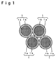
- the particles of the hydrogen absorbing alloy are treated in the acid solution in the second step, and the particles of the hydrogen absorbing alloy are then heat-treated and sintered at a temperature of not more than the melting point of the particles of the hydrogen absorbing alloy in the hydrogen atmosphere in the third step, as described above, a surface region 1b where the respective abundance ratios of nickel atoms, cobalt atoms, and manganese atoms are higher than those in an inner bulk region 1a is formed, and the particles 1 of the hydrogen absorbing alloy are welded together in the surface region 1b. Accordingly, contact resistance between the particles 1 of the hydrogen absorbing alloy is reduced.
- a conductive core member is filled with the particles of the hydrogen absorbing alloy thus obtained, to produce a hydrogen absorbing alloy electrode for an alkaline storage battery.
- the hydrogen absorbing alloy electrode for an alkaline storage battery thus produced is used for a negative electrode to obtain an alkaline storage battery, a lot of active metal nickel, metal cobalt, and so forth appear on the surface of the hydrogen absorbing alloy, so that the activity in the early stages of the hydrogen absorbing alloy is sufficiently improved. Accordingly, an initial battery capacity is increased.
- the particles of the hydrogen absorbing alloy are welded together in the surface region, so that the contact resistance between the particles of the hydrogen absorbing alloy is reduced. Accordingly, high-rate discharge characteristics in the alkaline storage battery are also improved.
- a hydrogen absorbing alloy for an alkaline storage battery in each of examples of the present invention and a method of producing the same as well as a hydrogen absorbing alloy electrode for an alkaline storage battery and a method of producing the same will be specifically described, and a comparative example is taken, to clarify that those in the examples of the present invention are superior.
- the hydrogen absorbing alloy for an alkaline storage battery in the present invention and the method of producing the same as well as the hydrogen absorbing alloy electrode for an alkaline storage battery and the method of producing the same are not limited to those in the following examples, and can be embodied by being suitably changed in a range in which the gist thereof is not changed.
- Misch metal (Mm) which is a mixture of rare earth elements containing 25 % by weight of La, 50 % by weight of Ce, 7 % by weight of Pr, and 18 % by weight of Nd and Ni, Co, Mn and Al having a purity of 99.9 % were mixed at a molar ratio of 1.0 : 3.1 : 0.9 : 0.6 : 0.4.
- a mixture obtained was dissolved by an arc melting furnace in an argon atmosphere, and was then naturally cooled, to produce an ingot of a hydrogen absorbing alloy indicated by a composition formula MmNi 3.1 Co 0.9 Mn 0.6 Al 0.4 .
- the ingot of the hydrogen absorbing alloy was mechanically ground in the air and classified, to obtain particles of the hydrogen absorbing alloy having an average particle diameter of 80 ⁇ m.
- a hydrochloric acid solution was used as the acid solution.
- Nickel chloride NiCl 2 which is a nickel compound was contained in the hydrochloric acid solution at a ratio of 0 % by weight to 10.0 % by weight, as shown in the following Table 1, to the particles of the hydrogen absorbing alloy, and the pH of the hydrochloric acid solution was adjusted to 1.0.
- the particles of the hydrogen absorbing alloy were treated upon being immersed in the hydrochloric acid solution for thirty minutes while being agitated. Thereafter, the particles of the hydrogen absorbing alloy thus treated were sucked in and filtered, and were rinsed and dried.
- the particles of the hydrogen absorbing alloy were sintered at a temperature of 600°C under the hydrogen atmosphere for six hours, to obtain particles of each of the hydrogen absorbing alloys in the examples 1 to 10.
- the melting point of the particles of the hydrogen absorbing alloy was approximately 1200°C.
- nickel chloride NiCl 2 which is a nickel compound was not added to a hydrochloric acid solution, and the particles of the hydrogen absorbing alloy were immersed in the hydrochloric acid solution having a pH of 0.3 and having a liquid temperature of 25°C for thirty minutes while being agitated. Thereafter, the particles of the hydrogen absorbing alloy thus treated were sucked in and filtered, and were rinsed and dried.
- the particles of the hydrogen absorbing alloy thus treated were then sintered at a temperature of 600°C under a hydrogen atmosphere for six hours, as in the examples 1 to 10, to obtain particles of the hydrogen absorbing alloy in the comparative example 1.
- the abundance ratio (atm%) of each of atoms in a surface region and the abundance ratio (atm%) of the atom in an inner bulk region were respectively measured using a scanning type transmission electron microscope and an energy dispersion type X-ray analysis meter.
- the abundance ratio of the nickel atoms was 70.7 atm%
- the abundance ratio of the cobalt atoms was 16.7 atm%
- the abundance ratio of the manganese atoms was 4.6 atm%
- the sum a of the abundance ratios was 92.0 atm%.
- the abundance ratio of the nickel atoms was 51.7 atm%
- the abundance ratio of the cobalt atoms was 15.1 atm%
- the abundance ratio of the manganese atoms was 9.9 atm%
- the sum b of the abundance ratios was 76.7 atm%.
- the value of a/b was 1.20.
- a hydrogen absorbing alloy electrode was then produced using the particles of each of the hydrogen absorbing alloys in the examples 1 to 10 and the comparative example 1 obtained in the above-mentioned manner.
- each of the hydrogen absorbing alloy electrodes 100 parts by weight of the particles of each of the hydrogen absorbing alloys in the examples 1 to 10 and the comparative example 1 and 20 parts by weight of a 5 % solution by weight of polyethylene oxide (PEO) which is a binder were mixed to prepare paste. Both surfaces of a conductive core member composed of a punching metal which was nickel-plated were coated and filled with the paste, and the conductive core member filled and coated with the paste was then dried at room temperature, and was then cut to a predetermined size, to produce the hydrogen absorbing alloy electrode.
- PEO polyethylene oxide
- Each of the hydrogen absorbing alloy electrodes thus produced was used as a negative electrode, while a sintered nickel electrode was used as a positive electrode.
- a non woven fabric having alkali resistance was used for a separator, and a 30 % potassium hydroxide solution by weight was used as an alkaline electrolyte, to produce an alkaline storage battery of a positive electrode control type of AA size and having a battery capacity of 1000 mAh, as shown in Fig. 2.
- a separator 13 was interposed between a positive electrode 11 and a negative electrode 12, the positive electrodes 11, the negative electrodes 12, and the separators 13 were wound in a spiral shape and were contained in a battery can 14, after which the alkaline electrolyte was poured into the battery can 14, and the battery can 14 was sealed, as shown in Fig. 2.
- the positive electrode 11 was connected to a positive electrode cover 15 through a positive electrode lead 11a, and the negative electrode 12 is connected to the battery can 14 through a negative electrode lead 12a, to electrically separate the battery can 14 and the positive electrode cover 15 from each other by an insulating packing 16.
- a coil spring 18 is provided between the positive electrode cover 15 and a positive electrode external terminal 17. When the internal pressure of the battery is abnormally raised, the coil spring 18 is compressed so that gas inside the battery is released in the air.
- each of the alkaline storage batteries produced in the above-mentioned manner was charged at a current value of 0.2 C under room temperature for six hours, and was then discharged to 1.0 V at a current value of 0.2 C, to measure a discharge capacity in the first cycle.
- the discharge capacity in the first cycle was taken as an initial discharge capacity.
- the initial discharge capacity was found in the above-mentioned manner, and each of the alkaline storage batteries was then charged and discharged in three cycles in the same manner as described above. Thereafter, the alkaline storage battery was charged at a current value of 0.2 C under room temperature for six hours, and was discharged to 1.0 V at a high current value of 6.0 C. The discharge capacity was measured, and was taken as a high-rate discharge capacity.
- the particles of the hydrogen absorbing alloys in the examples 1 to 10 so adapted that in the second step in which the particles of the hydrogen absorbing alloy were treated in the acid solution, the particles of the hydrogen absorbing alloy were treated in a hydrochloric acid solution containing 0 % by weight to 10.0 % by weight of nickel chloride NiCl 2 which is a nickel compound in the particles of the hydrogen absorbing alloy and having a pH adjusted to 1.0, the ratio (a/b) of the sum a (atm%) of the respective abundance ratios of nickel atoms, cobalt atoms, and manganese atoms in the surface region to the sum b (atm%) of the respective abundance ratios of nickel atoms, cobalt atoms, and manganese atoms in the bulk region was not less than 1.20, and the value of a/b was increased as the amount of the nickel chloride NiCl 2 contained in the hydrochloric acid solution was increased.
- the initial discharge capacity and the high-rate discharge capacity were made larger, as compared with those in the alkaline storage battery produced using the particles of the hydrogen absorbing alloy in the comparative example 1 in which the value of a/b was as low as 1.14.
- the initial discharge capacity assumed a high value of 800 mAh to 840 mAh
- the high-rate discharge capacity assumed a high value of 800 mAh to 840 mAh.
- the hydrochloric acid solution was used as the acid solution in the second step, the same effect also appeared in a case where a nitric acid solution, a phosphoric acid solution, or the like was used. Further, nickel chloride NiCl 2 was contained in the hydrochloric acid solution. However, the same effect also appeared in a case where another nickel compound such as nickel hydroxide Ni(OH) 2 or a cobalt compound such as cobalt chloride CoCl 2 or cobalt hydroxide Co(OH) 2 was contained.
- the particles of the hydrogen absorbing alloys thus treated in the acid solution at a temperature of not more than the melting point under a hydrogen atmosphere were sintered at a temperature of 600°C under a hydrogen atmosphere for six hours, as in the examples 1 to 10.
- a hydrogen absorbing alloy electrode was produced, as in the examples 1 to 10, using the particles of each of the hydrogen absorbing alloys in the examples 11 to 15 obtained in the above-mentioned manner, and an alkaline storage battery of a positive electrode control type of AA size and having a battery capacity of 1000 mAh was produced using the hydrogen absorbing alloy.
- an initial discharge capacity (mAh) and a high-rate discharge capacity (mAh) were also found, as in the examples 1 to 10.
- the particles of the hydrogen absorbing alloys in the examples 7 and 11 to 15 so adapted that in the second step in which the particles of the hydrogen absorbing alloy were treated in the acid solution, the particles of the hydrogen absorbing alloy were treated in a hydrochloric acid solution containing 3.0 % by weight of nickel chloride NiCl 2 which is a nickel compound in the particles of the hydrogen absorbing alloy and having a pH adjusted in the range of 0.3 to 3.0, the ratio (a/b) of the sum a (atm%) of the respective abundance ratios of nickel atoms, cobalt atoms, and manganese atoms in the surface region to the sum b (atm%) of the respective abundance ratios of nickel atoms, cobalt atoms, and manganese atoms in the bulk region was not less than 1.20.
- the value of a/b was the highest, i.e., 1.27.
- the reason for this is conceivably that the nickel atoms and the cobalt atoms in the surface region were also dissolved, and the respective numbers of the nickel atoms and the cobalt atoms in the surface region were reduced when the pH of the hydrochloric acid solution is too low, while an oxide coating on the surface of each of the particles of the hydrogen absorbing alloy was not sufficiently removed when the pH of the hydrochloric acid solution was increased.
- the initial discharge capacity and the high-rate discharge capacity were larger, as compared with those in the alkaline storage battery produced using the particles of the hydrogen absorbing alloy in the comparative example 1.
- the initial discharge capacity assumed a high value of 830 mAh to 840 mAh
- the high-rate discharge capacity assumed a high value of 835 mAh to 840 mAh.
- the pH thereof was set in the range of 0.7 to 2.0.
- the hydrochloric acid solution was also used as the acid solution in the second step, the same effect also appeared in a case where a nitric acid solution, a phosphoric acid solution, or the like was used. Further, nickel chloride NiCl 2 was contained in the hydrochloric acid solution. However, the same effect also appeared in a case where another nickel compound such as nickel hydroxide Ni(OH) 2 and a cobalt compound such as cobalt chloride CoCl 2 or cobalt hydroxide Co(OH) 2 were contained.
- the particles of the hydrogen absorbing alloy obtained by grinding the mass of the hydrogen absorbing alloy were produced using an arc furnace in an argon atmosphere
- the particles of the hydrogen absorbing alloy can be also produced using a gas atomizing method or a roll quenching method. The same effect also appeared in a case where the particles of the hydrogen absorbing alloy, which were easy to sinter, thus obtained by the gas atomizing method or the roll quenching method were used.
- a hydrogen absorbing alloy for an alkaline storage battery in the present invention and a hydrogen absorbing alloy for an alkaline storage battery obtained by a method of producing the hydrogen absorbing alloy for an alkaline storage battery in the present invention, a lot of active metal nickel and metal cobalt appear on the surface of each of particles of the hydrogen absorbing alloy, and the metal nickel and metal cobalt are prevented from being oxidized again. Further, the particles of the hydrogen absorbing alloy are welded together in a surface region in the hydrogen absorbing alloy.
Landscapes
- Chemical & Material Sciences (AREA)
- Chemical Kinetics & Catalysis (AREA)
- Electrochemistry (AREA)
- General Chemical & Material Sciences (AREA)
- Battery Electrode And Active Subsutance (AREA)
Abstract
A hydrogen absorbing alloy for an alkaline storage
battery having a crystal structure of a CaCu5 type and
represented by a composition formula MmNixCoyMnzM1-z (in the
formula, M is at least one element selected from aluminum
Al and copper Cu, x is a composition ratio of nickel Ni and
satisfies 3.0 ≦ x ≦ 5.2, y is a composition ratio of
cobalt Co and satisfies 0 ≦ y ≦ 1.2, and z is a
composition ratio of manganese Mn and satisfies 0.1 ≦ z ≦
0.9, with the proviso that the sum of x, y, and z satisfies
4.4 ≦ x + y + z ≦ 5.4 ) is so adapted as to have a surface
region and a bulk region covered with the surface region
and satisfy the condition of a/b ≧ 1.2, letting a be the
sum of the respective abundance ratios of atoms Ni, Co, and
Mn in the surface region and letting b the sum of the
respective abundance ratios of atoms Ni, Co, and Mn in the
bulk region.
Description
The present invention relates generally to a hydrogen
absorbing alloy for an alkaline storage battery used as a
negative electrode material for an alkaline storage battery
and a method of producing the same, and a hydrogen
absorbing alloy electrode for an alkaline storage battery
and a method of producing the same, and is particularly
characterized in that the hydrogen absorbing alloy is
treated to enhance the activity in the early stages of the
hydrogen absorbing alloy, to increase an initial discharge
capacity as well as to improve high-rate discharge
characteristics in the alkaline storage battery using the
hydrogen absorbing alloy.
Conventionally, nickel-cadmium storage batteries
have been generally used as alkaline storage batteries.
However, in recent years, nickel-hydrogen storage batteries
using a hydrogen absorbing alloy as a negative electrode
material have been paid attention to in that they have a
high capacity which is not less than twice that of the
nickel cadmium storage batteries and are also superior in
environmental safety because they do not use cadmium.
The nickel-hydrogen storage batteries have been used
for various types of portable equipment. It is expected to
further improve the performance of the nickel-hydrogen
storage batteries.
In the nickel-hydrogen storage batteries, examples of
the hydrogen absorbing alloy used for the negative
electrode material include an Mm type hydrogen absorbing
alloy using Mish metal (Mm) which is a mixture of rare
earth elements and a Laves type hydrogen absorbing alloy.
In the hydrogen absorbing alloy, however, an oxide
coating is generally easy to form on its surface by natural
oxidation or the like. When a hydrogen absorbing alloy
electrode is produced using the hydrogen absorbing alloy
having the oxide coating thus formed on its surface, and is
used for a negative electrode of the nickel-hydrogen
storage battery, there are some problems. For example, the
activity in the early stages of the hydrogen absorbing
alloy is low, so that an initial battery capacity in the
nickel-hydrogen storage battery is reduced.
Therefore, in recent years, a method of immersing a
hydrogen absorbing alloy in an acid solution such as a
hydrochloric acid solution, to remove an oxide coating on
the surface of the hydrogen absorbing alloy has been
proposed, as disclosed in JP-A-5-225975.
When the hydrogen absorbing alloy is thus immersed in
the acid solution, to remove the oxide coating on the
surface of the hydrogen absorbing alloy, active metal
nickel Ni, metal cobalt Co, and so forth appear on the
surface of the hydrogen absorbing alloy. However, the
active metal nickel and metal cobalt are oxidized again.
The activity in the early stages of the hydrogen absorbing
alloy cannot be sufficiently improved, so that the initial
battery capacity in the nickel-hydrogen storage battery is
still low.
When the active metal nickel, metal cobalt, and so
forth appear upon removal of the oxide coating on the
surface of the hydrogen absorbing alloy, as described
above, electrochemical contact resistance between particles
of the hydrogen absorbing alloy is reduced, so that the
high-rate discharge characteristics in the nickel-hydrogen
storage battery are slightly improved. However, contact
between the particles of the hydrogen absorbing alloy is
not sufficient. Consequently, the contact resistance
between the particles of the hydrogen absorbing alloy is
still high, so that the high-rate discharge characteristics
cannot be greatly improved.
The present invention solves various problems, as
described above, in an alkaline storage battery using a
hydrogen absorbing alloy as a negative electrode material.
Specifically, an object of the present invention is to
enhance the activity in the early stages of a hydrogen
absorbing alloy used as a negative electrode material of an
alkaline storage battery, to increase an initial battery
capacity and improve high-rate discharge characteristics in
the alkaline storage battery using the hydrogen absorbing
alloy.
A hydrogen absorbing alloy for an alkaline storage
battery in the present invention is a hydrogen absorbing
alloy having a crystal structure of a CaCu5 type and
represented by a composition formula MmNixCoyMnzM1-z (in the
formula, M is at least one element selected from aluminum
Al and copper Cu, x is a composition ratio of nickel Ni and
satisfies 3.0 ≦ x ≦ 5.2, y is a composition ratio of
cobalt Co and satisfies 0 ≦ y ≦ 1.2, and z is a
composition ratio of manganese Mn and satisfies 0.1 ≦ z ≦
0.9, with the proviso that the sum of x, y, and z satisfies
4.4 ≦ x + y + z ≦ 5.4 ), which has a surface region and a
bulk region covered with the surface region, the surface
region and the bulk region differing in composition, and
satisfies the condition of a/b ≧ 1.2, letting a be the sum
of the respective abundance ratios of atoms Ni, Co, and Mn
in the surface region and letting b the sum of the
respective abundance ratios of atoms Ni, Co, and Mn.
The surface region and the bulk region in the
hydrogen absorbing alloy are definitely distinguished by
observation using a scanning type transmission electron
microscope (TEM), and differ in composition. The surface
region is normally formed to a depth of approximately 80 nm
from the surface of the hydrogen absorbing alloy.
In determining the surface region and the bulk region
in the present invention, analysis is performed using the
scanning type transmission electron microscope and an
energy dispersion type X-ray analysis meter at spacing of
several nanometers from the surface of each of the
particles of the hydrogen absorbing alloy toward the center
thereof, and the respective abundance ratios of metal
elements at each of points of measurement are found. The
respective abundance ratios of the metal elements are
constant in a region inside of a certain point of
measurement. The point of measurement is taken as the
boundary, to take a region on the side of the surface from
the point of measurement as the surface region and take a
region on the side of the center from the point of
measurement as the bulk region.
The sum a of the respective abundance ratios (atm%)
of the atoms Ni, Co, and Mn in the surface region is a
value measured at a middle point between the surface of
each of the particles of the hydrogen absorbing alloy and
the boundary, and the sum b of the respective abundance
ratios (atm%) of the atoms Ni, Co, Mn in the bulk region is
a value measured at a point on the side of the center of
each of the particles of the hydrogen absorbing alloy from
the boundary in which the respective abundance ratios of
the metal elements are constant, as described above.
When a hydrogen absorbing alloy having a crystal
structure of a CaCu5 type and represented by a composition
formula MmNixCoyMnzM1-z (in the formula, M is at least one
element selected from aluminum Al and copper Cu, x is a
composition ratio of nickel Ni and satisfies 3.0 ≦ x ≦
5.2, y is a composition ratio of cobalt Co and satisfies 0
≦ y ≦ 1.2, and z is a composition ratio of manganese Mn
and satisfies 0.1 ≦ z ≦ 0.9, with the proviso that the
sum of x, y, and z satisfies 4.4 ≦ x + y + z ≦ 5.4 ) is
used as a negative electrode material of an alkaline
storage battery, as in the hydrogen absorbing alloy for an
alkaline storage battery in the present invention, the
hydrogen absorbing alloy is prevented from being corroded
in an alkaline electrolyte, to prevent the amount of
hydrogen absorbed by the hydrogen absorbing alloy from
being reduced.
In the hydrogen absorbing alloy, when the condition
of a/b ≧ 1.2 is satisfied, letting a be the sum of the
respective abundance ratios (atm%) of the atoms Ni, Co, and
Mn in the surface region and letting b be the sum of the
respective abundance rations (atm%) of the atoms Ni, Co,
and Mn in the bulk region, a lot of active Ni and Co exist
in the surface region in the hydrogen absorbing alloy, so
that the activity in the early stages of the hydrogen
absorbing alloy is improved. In the alkaline storage
battery using the hydrogen absorbing alloy, therefore, an
initial battery capacity is increased.
In a method of producing a hydrogen absorbing alloy
for an alkaline storage battery according to the present
invention, the first step of obtaining particles of a
hydrogen absorbing alloy having a crystal structure of a
CaCu5 type and represented by a composition formula
MmNixCoyMnzM1-z (in the formula, M is at least one element
selected from aluminum Al and copper Cu, x is a composition
ratio of nickel Ni and satisfies 3.0 ≦ x ≦ 5.2, y is a
composition ratio of cobalt Co and satisfies 0 ≦ y ≦ 1.2,
and z is a composition ratio of manganese Mn and satisfies
0.1 ≦ z ≦ 0.9, with the proviso that the sum of x, y, and
z satisfies 4.4 ≦ x + y + z ≦ 5.4 ), the second step of
treating the particles of the hydrogen absorbing alloy in
an acid solution, and the third step of heat-treating and
sintering the particles of the hydrogen absorbing alloy
treated in the acid solution at a temperature of not more
than the melting point of the particles of the hydrogen
absorbing alloy in a hydrogen atmosphere are carried out,
to obtain a hydrogen absorbing alloy for an alkaline
storage battery having a surface region and a bulk region
covered with the surface region and satisfying the
condition of a/b ≧ 1.2, letting a be the sum of the
respective abundance ratios (atm%) of atoms Ni, Co, and Mn
in the surface region and letting b the sum of the
respective abundance ratios (atm%) of atoms Ni, Co, and Mn.
In the foregoing first step, in obtaining the
particles of the hydrogen absorbing alloy, the mass of the
hydrogen absorbing alloy produced in an arc furnace in an
argon atmosphere is ground, to obtain the particles of the
hydrogen absorbing alloy. Further, it is possible to
obtain the particles of the hydrogen absorbing alloy by a
gas atomizing method, a roll quenching method, or the like.
In the foregoing second step, when the particles of
the hydrogen absorbing alloy are treated in the acid
solution, an oxide coating on the surface of each of the
particles of the hydrogen absorbing alloy is removed.
Accordingly, active metal nickel Ni and metal cobalt Co
appear on the surface of the particle of the hydrogen
absorbing alloy.
In the second step, examples of the acid solution for
treating the particles of the hydrogen absorbing alloy
include hydrochloric acid, sulfuric acid, and phosphoric
acid.
In treating the particles of the hydrogen absorbing
alloy in such an acid solution, when the pH of the acid
solution is too low, the particles of the hydrogen
absorbing alloy are rapidly oxidized, so that nickel and
cobalt on the surface of each of the particles of the
hydrogen absorbing alloy are also dissolved. On the other
hand, when the pH of the acid solution is high, the oxide
coating on the surface of the particle of the hydrogen
absorbing alloy is not sufficiently removed. Therefore, it
is preferable that the pH in the early stages of the acid
solution is in the range of 0.7 to 2.0.
In thus treating the particles of the hydrogen
absorbing alloy in the acid solution, it is preferable that
a nickel compound and a cobalt compound are added to the
acid solution. Examples of the nickel compound to be added
to the acid solution include nickel chloride NiCl2 and
nickel hydroxide Ni(OH)2. Examples of the cobalt compound
include cobalt chloride CoCl2 and cobalt hydroxide Co(OH)2.
When the nickel compound and the cobalt compound are
thus added to the acid solution to treat the particles of
the hydrogen absorbing alloy, the nickel compound and the
cobalt compound which have been added to the acid solution
are respectively reduced to metal nickel and metal cobalt.
The metal nickel and the metal cobalt thus reduced are
deposited on the surface of the hydrogen absorbing alloy,
so that a lot of active metal nickel and metal cobalt
appear on the surface of each of the particles of the
hydrogen absorbing alloy.
When the respective amounts of the nickel compound
and the cobalt compound to be added to the acid solution
are small, the respective amount of the metal nickel and
the metal cobalt to be deposited on the surface of the
hydrogen absorbing alloy are reduced, so that a lot of
active metal nickel and metal cobalt cannot appear on the
surface of each of the particles of the hydrogen absorbing
alloy. On the other hand, when the respective amounts of
the nickel compound and the cobalt compound to be added are
too large, the respective amounts of the metal nickel and
metal cobalt to be deposited on the surface of the particle
of the hydrogen absorbing alloy are excessive.
Accordingly, the surface of the particle of the hydrogen absorbing alloy is easily oxidized. Therefore, it is preferable that the respective amounts of the nickel compound and the cobalt compound to be added to the acid solution are in the range of 0.3 to 5.0 % by weight of the particle of the hydrogen absorbing alloy.
Accordingly, the surface of the particle of the hydrogen absorbing alloy is easily oxidized. Therefore, it is preferable that the respective amounts of the nickel compound and the cobalt compound to be added to the acid solution are in the range of 0.3 to 5.0 % by weight of the particle of the hydrogen absorbing alloy.
When the particles of the hydrogen absorbing alloy
are thus treated in the acid solution, and the particles of
the hydrogen absorbing alloy are then heat-treated and
sintered at a temperature of not more than the melting
point of the particles of the hydrogen absorbing alloy in a
hydrogen atmosphere, an oxide on the surface of each of the
particles of the hydrogen absorbing alloy is reduced, and
manganese Mn contained in the particle of the hydrogen
absorbing alloy is moved to the surface of the particle of
the hydrogen absorbing alloy. The melting point of the
particles of the hydrogen absorbing alloy having the above-mentioned
composition is generally in the range of 1100°C
to 1300°C and specifically, in the range of 1180°C and
1250°C. The particles of the hydrogen absorbing alloy is
heat-treated at a temperature lower than the melting point.
The manganese Mn moved to the surface of the particle
of the hydrogen absorbing alloy as described above is
oxidized more easily than the metal nickel and the metal
cobalt on the surface of the particle of the hydrogen
absorbing alloy. The manganese is first oxidized on the
surface of the particle of the hydrogen absorbing alloy, so
that the metal nickel and the metal cobalt are prevented
from being oxidized again. When the hydrogen absorbing
alloy electrode using the particles of the hydrogen
absorbing alloy is used as the alkaline storage battery,
the manganese or an oxide of the manganese on the surface
of the particle of the hydrogen absorbing alloy is
gradually dissolved in the alkaline electrolyte in the
alkaline storage battery, not to degrade the activity on
the surface of the particle of the hydrogen absorbing
alloy.
When the particles of the hydrogen absorbing alloy
are treated in the acid solution in the second step, and
the particles of the hydrogen absorbing alloy are then
heat-treated and sintered at a temperature of not more than
the melting point of the particles of the hydrogen
absorbing alloy in the hydrogen atmosphere in the third
step, as described above, a surface region 1b where the
respective abundance ratios of nickel atoms, cobalt atoms,
and manganese atoms are higher than those in an inner bulk
region 1a is formed, and the particles 1 of the hydrogen
absorbing alloy are welded together in the surface region
1b. Accordingly, contact resistance between the particles
1 of the hydrogen absorbing alloy is reduced.
A conductive core member is filled with the particles
of the hydrogen absorbing alloy thus obtained, to produce a
hydrogen absorbing alloy electrode for an alkaline storage
battery.
When the hydrogen absorbing alloy electrode for an
alkaline storage battery thus produced is used for a
negative electrode to obtain an alkaline storage battery, a
lot of active metal nickel, metal cobalt, and so forth
appear on the surface of the hydrogen absorbing alloy, so
that the activity in the early stages of the hydrogen
absorbing alloy is sufficiently improved. Accordingly, an
initial battery capacity is increased. The particles of
the hydrogen absorbing alloy are welded together in the
surface region, so that the contact resistance between the
particles of the hydrogen absorbing alloy is reduced.
Accordingly, high-rate discharge characteristics in the
alkaline storage battery are also improved.
A hydrogen absorbing alloy for an alkaline storage
battery in each of examples of the present invention and a
method of producing the same as well as a hydrogen
absorbing alloy electrode for an alkaline storage battery
and a method of producing the same will be specifically
described, and a comparative example is taken, to clarify
that those in the examples of the present invention are
superior. The hydrogen absorbing alloy for an alkaline
storage battery in the present invention and the method of
producing the same as well as the hydrogen absorbing alloy
electrode for an alkaline storage battery and the method of
producing the same are not limited to those in the
following examples, and can be embodied by being suitably
changed in a range in which the gist thereof is not
changed.
In the examples, in producing particles of a
hydrogen absorbing alloy, as shown in the foregoing first
step, Misch metal (Mm) which is a mixture of rare earth
elements containing 25 % by weight of La, 50 % by weight of
Ce, 7 % by weight of Pr, and 18 % by weight of Nd and Ni,
Co, Mn and Al having a purity of 99.9 % were mixed at a
molar ratio of 1.0 : 3.1 : 0.9 : 0.6 : 0.4. A mixture
obtained was dissolved by an arc melting furnace in an
argon atmosphere, and was then naturally cooled, to produce
an ingot of a hydrogen absorbing alloy indicated by a
composition formula MmNi3.1Co0.9Mn0.6Al0.4. The ingot of the
hydrogen absorbing alloy was mechanically ground in the air
and classified, to obtain particles of the hydrogen
absorbing alloy having an average particle diameter of 80
µm.
In then treating the particles of the hydrogen
absorbing alloy in an acid solution, as shown in the
foregoing second step, a hydrochloric acid solution was
used as the acid solution. Nickel chloride NiCl2 which is
a nickel compound was contained in the hydrochloric acid
solution at a ratio of 0 % by weight to 10.0 % by weight,
as shown in the following Table 1, to the particles of the
hydrogen absorbing alloy, and the pH of the hydrochloric
acid solution was adjusted to 1.0. The particles of the
hydrogen absorbing alloy were treated upon being immersed
in the hydrochloric acid solution for thirty minutes while
being agitated. Thereafter, the particles of the hydrogen
absorbing alloy thus treated were sucked in and filtered,
and were rinsed and dried.
In heat-treating and sintering the particles of the
hydrogen absorbing alloy thus treated in the acid solution
at a temperature of not more than the melting point under a
hydrogen atmosphere, as shown in the foregoing third step,
the particles of the hydrogen absorbing alloy were sintered
at a temperature of 600°C under the hydrogen atmosphere for
six hours, to obtain particles of each of the hydrogen
absorbing alloys in the examples 1 to 10. The melting
point of the particles of the hydrogen absorbing alloy was
approximately 1200°C.
In the comparative example 1, particles of a hydrogen
absorbing alloy indicated by a composition formula
MmNi3.1Co0.9Mn0.6Al0.4 produced in the same manner as that in
the first step in each of the examples 1 to 10 were used.
In treating the particles of the hydrogen absorbing
alloy in an acid solution, nickel chloride NiCl2 which is a
nickel compound was not added to a hydrochloric acid
solution, and the particles of the hydrogen absorbing alloy
were immersed in the hydrochloric acid solution having a pH
of 0.3 and having a liquid temperature of 25°C for thirty
minutes while being agitated. Thereafter, the particles of
the hydrogen absorbing alloy thus treated were sucked in
and filtered, and were rinsed and dried.
The particles of the hydrogen absorbing alloy thus
treated were then sintered at a temperature of 600°C under
a hydrogen atmosphere for six hours, as in the examples 1
to 10, to obtain particles of the hydrogen absorbing alloy
in the comparative example 1.
With respect to the particles of each of the
hydrogen absorbing alloys in the examples 1 to 10 and the
comparative example 1 obtained in the above-mentioned
manner, the abundance ratio (atm%) of each of atoms in a
surface region and the abundance ratio (atm%) of the atom
in an inner bulk region were respectively measured using a
scanning type transmission electron microscope and an
energy dispersion type X-ray analysis meter.
With respect to the particles of each of the
hydrogen absorbing alloys in the examples 1 to 10 and the
comparative example 1, the sum a (atm%) of the respective
abundance ratios of nickel atoms, cobalt atoms, and
manganese atoms in the surface region and the sum b (atm%)
of the respective abundance ratios of nickel atoms, cobalt
atoms, and manganese atoms in the bulk region were found,
to calculate the value of a/b. The results thereof were
together shown in the following Table 1. In the particles
of the hydrogen absorbing alloy in the example 1, in the
surface region, the abundance ratio of the nickel atoms was
70.7 atm%, the abundance ratio of the cobalt atoms was 16.7
atm%, the abundance ratio of the manganese atoms was 4.6
atm%, and the sum a of the abundance ratios was 92.0 atm%.
On the other hand, in the bulk region, the abundance ratio
of the nickel atoms was 51.7 atm%, the abundance ratio of
the cobalt atoms was 15.1 atm%, the abundance ratio of the
manganese atoms was 9.9 atm%, and the sum b of the
abundance ratios was 76.7 atm%. The value of a/b was 1.20.
A hydrogen absorbing alloy electrode was then
produced using the particles of each of the hydrogen
absorbing alloys in the examples 1 to 10 and the
comparative example 1 obtained in the above-mentioned
manner.
In producing each of the hydrogen absorbing alloy
electrodes, 100 parts by weight of the particles of each of
the hydrogen absorbing alloys in the examples 1 to 10 and
the comparative example 1 and 20 parts by weight of a 5 %
solution by weight of polyethylene oxide (PEO) which is a
binder were mixed to prepare paste. Both surfaces of a
conductive core member composed of a punching metal which
was nickel-plated were coated and filled with the paste,
and the conductive core member filled and coated with the
paste was then dried at room temperature, and was then cut
to a predetermined size, to produce the hydrogen absorbing
alloy electrode.
Each of the hydrogen absorbing alloy electrodes thus
produced was used as a negative electrode, while a sintered
nickel electrode was used as a positive electrode. A non
woven fabric having alkali resistance was used for a
separator, and a 30 % potassium hydroxide solution by
weight was used as an alkaline electrolyte, to produce an
alkaline storage battery of a positive electrode control
type of AA size and having a battery capacity of 1000 mAh,
as shown in Fig. 2.
In producing each of the above-mentioned alkaline
storage batteries, a separator 13 was interposed between a
positive electrode 11 and a negative electrode 12, the
positive electrodes 11, the negative electrodes 12, and the
separators 13 were wound in a spiral shape and were
contained in a battery can 14, after which the alkaline
electrolyte was poured into the battery can 14, and the
battery can 14 was sealed, as shown in Fig. 2. The
positive electrode 11 was connected to a positive electrode
cover 15 through a positive electrode lead 11a, and the
negative electrode 12 is connected to the battery can 14
through a negative electrode lead 12a, to electrically
separate the battery can 14 and the positive electrode
cover 15 from each other by an insulating packing 16.
Further, a coil spring 18 is provided between the positive
electrode cover 15 and a positive electrode external
terminal 17. When the internal pressure of the battery is
abnormally raised, the coil spring 18 is compressed so that
gas inside the battery is released in the air.
With respect to the alkaline storage battery produced
using the particles of each of the hydrogen absorbing
alloys in the examples 1 to 10 and the comparative example
1, an initial discharge capacity (mAh) and a high-rate
discharge capacity (mAl) were found. The results thereof
were together shown in the following Table 1.
In finding the initial discharge capacity, each of
the alkaline storage batteries produced in the above-mentioned
manner was charged at a current value of 0.2 C
under room temperature for six hours, and was then
discharged to 1.0 V at a current value of 0.2 C, to measure
a discharge capacity in the first cycle. The discharge
capacity in the first cycle was taken as an initial
discharge capacity.
In finding the high-rate discharge capacity, the
initial discharge capacity was found in the above-mentioned
manner, and each of the alkaline storage batteries was then
charged and discharged in three cycles in the same manner
as described above. Thereafter, the alkaline storage
battery was charged at a current value of 0.2 C under room
temperature for six hours, and was discharged to 1.0 V at a
high current value of 6.0 C. The discharge capacity was
measured, and was taken as a high-rate discharge capacity.
| acid solution | a/b | initial discharge capacity (mAh) | high-rate discharge capacitu (mAh) | ||
| pH | content of NiCl2 | ||||
| example 1 | 1.0 | no added | 1.20 | 730 | 730 |
| example 2 | 1.0 | 0.3 % by weight | 1.21 | 810 | 800 |
| example 3 | 1.0 | 0.5 % by weight | 1.22 | 820 | 815 |
| example 4 | 1.0 | 0.7% by weight | 1.23 | 830 | 830 |
| example 5 | 1.0 | 1.0 % by weight | 1.24 | 830 | 835 |
| example 6 | 1.0 | 2.0 % by weight | 1.26 | 840 | 835 |
| example 7 | 1.0 | 3.0 % by weight | 1.27 | 840 | 840 |
| example 8 | 1.0 | 5.0 % by weight | 1.28 | 820 | 835 |
| example 9 | 1.0 | 7.0 % by weight | 1.29 | 780 | 775 |
| example 10 | 1.0 | 10.0 % by weight | 1.29 | 770 | 760 |
| comparative example 1 | 0.3 | no added | 1.14 | 670 | 690 |
As a result, in the particles of each of the hydrogen
absorbing alloys in the examples 1 to 10 so adapted that in
the second step in which the particles of the hydrogen
absorbing alloy were treated in the acid solution, the
particles of the hydrogen absorbing alloy were treated in a
hydrochloric acid solution containing 0 % by weight to
10.0 % by weight of nickel chloride NiCl2 which is a nickel
compound in the particles of the hydrogen absorbing alloy
and having a pH adjusted to 1.0, the ratio (a/b) of the sum
a (atm%) of the respective abundance ratios of nickel
atoms, cobalt atoms, and manganese atoms in the surface
region to the sum b (atm%) of the respective abundance
ratios of nickel atoms, cobalt atoms, and manganese atoms
in the bulk region was not less than 1.20, and the value of
a/b was increased as the amount of the nickel chloride
NiCl2 contained in the hydrochloric acid solution was
increased.
On the other hand, in the particles of the hydrogen
absorbing alloy in the comparative example 1 in which in
treating the particles of the hydrogen absorbing alloy in
the acid solution, the particles of the hydrogen absorbing
alloy were treated in a hydrochloric acid solution
containing no nickel chloride NiCl2 which is a nickel
compound and having a pH adjusted to 0.3, the inside of
each of the particles of the hydrogen absorbing alloy was
also dissolved by the hydrochloric acid solution, and the
value of a/b was as low as 1.14.
In the alkaline storage battery produced using the
particles of each of hydrogen absorbing alloys in the
examples 1 to 10 in which the value of a/b was not less
than 1.20, the initial discharge capacity and the high-rate
discharge capacity were made larger, as compared with those
in the alkaline storage battery produced using the
particles of the hydrogen absorbing alloy in the
comparative example 1 in which the value of a/b was as low
as 1.14. Particularly, in the alkaline storage battery
using the particles of each of the hydrogen absorbing
alloys in the examples 2 to 8 treated using a hydrochloric
acid solution containing 0.3 % by weight to 5.0 % by weight
of nickel chloride NiCl2 to be contained in the
hydrochloric acid solution to the particle of the hydrogen
absorbing alloy, the initial discharge capacity assumed a
high value of 800 mAh to 840 mAh, and the high-rate
discharge capacity assumed a high value of 800 mAh to 840
mAh. In treating the particles of the hydrogen absorbing
alloy in the hydrochloric acid solution, it was preferable
that 0.3 % by weight to 5.0 % by weight of NiCl2 was added
to the particles of the hydrogen absorbing alloy.
Although in the examples 1 to 10, the hydrochloric
acid solution was used as the acid solution in the second
step, the same effect also appeared in a case where a
nitric acid solution, a phosphoric acid solution, or the
like was used. Further, nickel chloride NiCl2 was
contained in the hydrochloric acid solution. However, the
same effect also appeared in a case where another nickel
compound such as nickel hydroxide Ni(OH)2 or a cobalt
compound such as cobalt chloride CoCl2 or cobalt hydroxide
Co(OH)2 was contained.
Also in the examples 11 to 15, particles of a
hydrogen absorbing alloy represented by a composition
formula MmNi3.1Co0.9Mn0.6Al0.4 produced in the same manner as
that in the foregoing first step in each of the examples 1
to 10 were used.
In treating the particles of the hydrogen absorbing
alloy in an acid solution, as shown in the foregoing second
step, 0.3 % by weight of nickel chloride NiCl2 which is a
nickel compound was contained in the particles of the
hydrogen absorbing alloy, as in the example 7, while the
particles of the hydrogen absorbing alloy were treated in
the hydrochloric acid solution in the same manner as those
in the examples 1 to 10 except that the pH of the
hydrochloric acid solution was changed in the range of 0.3
to 3.0, as shown in the following Table 2.
In heat-treating and sintering the particles of each
of the hydrogen absorbing alloys thus treated in the acid
solution at a temperature of not more than the melting
point under a hydrogen atmosphere, as in the third step,
the particles of the hydrogen absorbing alloy were sintered
at a temperature of 600°C under a hydrogen atmosphere for
six hours, as in the examples 1 to 10.
With respect to the particles of each of the hydrogen
absorbing alloys in the examples 11 to 15 thus obtained,
the sum a (atm%) of the respective abundance ratios of
nickel atoms, cobalt atoms, and manganese atoms in a
surface region and the sum b (atm%) of the respective
abundance ratios of nickel atoms, cobalt atoms and
manganese atoms in a bulk region were also found, as in the
examples 1 to 10, to calculate the value of a/b. The
results thereof were together shown in the following Table
2.
A hydrogen absorbing alloy electrode was produced, as
in the examples 1 to 10, using the particles of each of the
hydrogen absorbing alloys in the examples 11 to 15 obtained
in the above-mentioned manner, and an alkaline storage
battery of a positive electrode control type of AA size and
having a battery capacity of 1000 mAh was produced using
the hydrogen absorbing alloy.
With respect to each of the alkaline storage
batteries, an initial discharge capacity (mAh) and a high-rate
discharge capacity (mAh) were also found, as in the
examples 1 to 10. The results thereof, together with those
in the example 7, were shown in the following Table 2.
| acid solution | a/b | initial discharge capacity (mAh) | high-rate discharge capacitu (mAh) | ||
| pH | content of NiCl2 | ||||
| example 11 | 0.3 | 3.0 % by weight | 1.20 | 770 | 780 |
| example 12 | 0.5 | 3.0 % by weight | 1.22 | 790 | 795 |
| example 13 | 0.7 | 3.0 % by weight | 1.25 | 830 | 840 |
| example 7 | 1.0 | 3.0 % by weight | 1.27 | 840 | 840 |
| example 14 | 2.0 | 3.0 % by weight | 1.25 | 830 | 835 |
| example 15 | 3.0 | 3.0 % by weight | 1.20 | 790 | 795 |
As a result, in the particles of each of the hydrogen
absorbing alloys in the examples 7 and 11 to 15 so adapted
that in the second step in which the particles of the
hydrogen absorbing alloy were treated in the acid solution,
the particles of the hydrogen absorbing alloy were treated
in a hydrochloric acid solution containing 3.0 % by weight
of nickel chloride NiCl2 which is a nickel compound in the
particles of the hydrogen absorbing alloy and having a pH
adjusted in the range of 0.3 to 3.0, the ratio (a/b) of the
sum a (atm%) of the respective abundance ratios of nickel
atoms, cobalt atoms, and manganese atoms in the surface
region to the sum b (atm%) of the respective abundance
ratios of nickel atoms, cobalt atoms, and manganese atoms
in the bulk region was not less than 1.20. Particularly in
the particles of the hydrogen absorbing alloy in the
example 7 treated using a hydrochloric acid solution having
a pH of 1.0, the value of a/b was the highest, i.e., 1.27.
The reason for this is conceivably that the nickel atoms
and the cobalt atoms in the surface region were also
dissolved, and the respective numbers of the nickel atoms
and the cobalt atoms in the surface region were reduced
when the pH of the hydrochloric acid solution is too low,
while an oxide coating on the surface of each of the
particles of the hydrogen absorbing alloy was not
sufficiently removed when the pH of the hydrochloric acid
solution was increased.
Also in the alkaline storage battery produced using
the particles of each of the hydrogen absorbing alloys in
the examples 11 to 15, the initial discharge capacity and
the high-rate discharge capacity were larger, as compared
with those in the alkaline storage battery produced using
the particles of the hydrogen absorbing alloy in the
comparative example 1. Particularly in the alkaline
storage battery using the particles of each of the hydrogen
absorbing alloys in the examples 13, 7, and 14 treated with
the pH of the hydrochloric acid solution set in the range
of 0.7 to 2.0, the initial discharge capacity assumed a
high value of 830 mAh to 840 mAh, and the high-rate
discharge capacity assumed a high value of 835 mAh to 840
mAh. In treating the particles of the hydrogen absorbing
alloy in the hydrochloric acid solution, it was preferable
that the pH thereof was set in the range of 0.7 to 2.0.
Although in each of the examples 11 to 15, the
hydrochloric acid solution was also used as the acid
solution in the second step, the same effect also appeared
in a case where a nitric acid solution, a phosphoric acid
solution, or the like was used. Further, nickel chloride
NiCl2 was contained in the hydrochloric acid solution.
However, the same effect also appeared in a case where
another nickel compound such as nickel hydroxide Ni(OH)2
and a cobalt compound such as cobalt chloride CoCl2 or
cobalt hydroxide Co(OH)2 were contained.
Although in each of the examples, in producing the
particles of the hydrogen absorbing alloy in the first
step, the particles of the hydrogen absorbing alloy
obtained by grinding the mass of the hydrogen absorbing
alloy were produced using an arc furnace in an argon
atmosphere, the particles of the hydrogen absorbing alloy
can be also produced using a gas atomizing method or a roll
quenching method. The same effect also appeared in a case
where the particles of the hydrogen absorbing alloy, which
were easy to sinter, thus obtained by the gas atomizing
method or the roll quenching method were used.
As described in detail above, in a hydrogen
absorbing alloy for an alkaline storage battery in the
present invention and a hydrogen absorbing alloy for an
alkaline storage battery obtained by a method of producing
the hydrogen absorbing alloy for an alkaline storage
battery in the present invention, a lot of active metal
nickel and metal cobalt appear on the surface of each of
particles of the hydrogen absorbing alloy, and the metal
nickel and metal cobalt are prevented from being oxidized
again. Further, the particles of the hydrogen absorbing
alloy are welded together in a surface region in the
hydrogen absorbing alloy.
When a hydrogen absorbing alloy electrode for an
alkaline storage battery using the hydrogen absorbing alloy
is used as a negative electrode of the alkaline storage
battery, the activity in the early stages of the hydrogen
absorbing alloy is enhanced, so that an initial battery
capacity in the alkaline storage battery is improved.
Further, contact resistance between the particles of the
hydrogen absorbing alloy is reduced, so that high-rate
discharge characteristics in the alkaline storage battery
are also improved.
Claims (7)
- A hydrogen absorbing alloy for an alkaline storage battery having a crystal structure of a CaCu5 type and represented by a composition formula MmNixCoyMnzM1-z (in the formula, M is at least one element selected from aluminum Al and copper Cu, x is a composition ratio of nickel Ni and satisfies 3.0 ≦ x ≦ 5.2, y is a composition ratio of cobalt Co and satisfies 0 ≦ y ≦ 1.2, and z is a composition ratio of manganese Mn and satisfies 0.1 ≦ z ≦ 0.9, with the proviso that the sum of x, y, and z satisfies
- A method of producing a hydrogen absorbing alloy for an alkaline storage battery, characterized in that the first step of obtaining particles of a hydrogen absorbing alloy having a crystal structure of a CaCu5 type and represented by a composition formula MmNixCoyMnzM1-z (in the formula, M is at least one element selected from aluminum Al, and copper Cu, x is a composition ratio of nickel Ni and satisfies 3.0 ≦ x ≦ 5.2, y is a composition ratio of cobalt Co and satisfies 0 ≦ y ≦ 1.2, and z is a composition ratio of manganese Mn and satisfies 0.1 ≦ z ≦ 0.9, with the proviso that the sum of x, y, and z satisfies
- The method according to claim 2, characterized in that at least one of a nickel compound and a cobalt compound is added to the acid solution in said second step.
- The method according to claim 3, characterized in that in adding at least one of a nickel compound and a cobalt compound to the acid solution, the amount of the compound to be added is in the range of 0.3 to 5.0 % by weight of the particles of the hydrogen absorbing alloy.
- The method according to claim 2, characterized in that the pH of the acid solution in said second step is in the range of 0.7 to 2.0.
- A hydrogen absorbing alloy electrode for an alkaline storage battery, characterized in that a conductive core member is filled with the hydrogen absorbing alloy for an alkaline storage battery according to claim 1.
- A hydrogen absorbing alloy electrode for an alkaline storage battery, characterized in that a conductive core member is filled with the hydrogen absorbing alloy for an alkaline storage battery according to claim 1.
Applications Claiming Priority (3)
| Application Number | Priority Date | Filing Date | Title |
|---|---|---|---|
| JP17152798 | 1998-06-18 | ||
| JP17152798 | 1998-06-18 | ||
| PCT/JP1999/003234 WO1999066573A1 (en) | 1998-06-18 | 1999-06-16 | Hydrogen absorbing alloy for alkaline storage battery and method for production thereof, and hydrogen absorbing alloy electrode for alkaline storage battery and method for production thereof |
Publications (2)
| Publication Number | Publication Date |
|---|---|
| EP1096584A1 true EP1096584A1 (en) | 2001-05-02 |
| EP1096584A4 EP1096584A4 (en) | 2007-05-16 |
Family
ID=15924787
Family Applications (1)
| Application Number | Title | Priority Date | Filing Date |
|---|---|---|---|
| EP99925358A Withdrawn EP1096584A4 (en) | 1998-06-18 | 1999-06-16 | Hydrogen absorbing alloy for alkaline storage battery and method for production thereof, and hydrogen absorbing alloy electrode for alkaline storage battery and method for production thereof |
Country Status (3)
| Country | Link |
|---|---|
| EP (1) | EP1096584A4 (en) |
| CN (1) | CN1155131C (en) |
| WO (1) | WO1999066573A1 (en) |
Families Citing this family (1)
| Publication number | Priority date | Publication date | Assignee | Title |
|---|---|---|---|---|
| JP7333358B2 (en) * | 2021-03-03 | 2023-08-24 | プライムアースEvエナジー株式会社 | Nickel metal hydride storage battery |
Family Cites Families (11)
| Publication number | Priority date | Publication date | Assignee | Title |
|---|---|---|---|---|
| JPH05179372A (en) * | 1992-01-06 | 1993-07-20 | Tokin Corp | Method for producing hydrogen storage alloy powder |
| JPH0963573A (en) * | 1995-08-23 | 1997-03-07 | Toyota Autom Loom Works Ltd | Manufacture of hydrogen storage alloy electrode |
| JP3201247B2 (en) * | 1996-02-05 | 2001-08-20 | 松下電器産業株式会社 | Sealed alkaline storage battery |
| JPH09237628A (en) * | 1996-02-29 | 1997-09-09 | Sanyo Electric Co Ltd | Production of hydrogen storage alloy electrode |
| JP3433002B2 (en) * | 1996-06-10 | 2003-08-04 | 三洋電機株式会社 | Method for producing hydrogen storage alloy and hydrogen storage alloy electrode |
| EP1713139A1 (en) * | 1996-06-26 | 2006-10-18 | Sanyo Electric Co., Ltd. | Hydrogen-absorbing alloy electrode and process for making the same |
| JPH1021907A (en) * | 1996-07-01 | 1998-01-23 | Chuo Denki Kogyo Kk | Method for producing hydrogen storage alloy powder and Ni-hydrogen battery |
| JPH1050309A (en) * | 1996-07-30 | 1998-02-20 | Yuasa Corp | Hydrogen storage alloy electrode and manufacture thereof |
| JP3433027B2 (en) * | 1996-09-27 | 2003-08-04 | 三洋電機株式会社 | Hydrogen storage alloy electrode and method of manufacturing hydrogen storage alloy electrode |
| JPH10149824A (en) * | 1996-11-20 | 1998-06-02 | Matsushita Electric Ind Co Ltd | Manufacturing method of hydrogen storage alloy electrode |
| JP3553750B2 (en) * | 1996-11-29 | 2004-08-11 | 三洋電機株式会社 | Method for producing hydrogen storage alloy for alkaline storage battery |
-
1999
- 1999-06-16 WO PCT/JP1999/003234 patent/WO1999066573A1/en not_active Ceased
- 1999-06-16 CN CNB998075493A patent/CN1155131C/en not_active Expired - Fee Related
- 1999-06-16 EP EP99925358A patent/EP1096584A4/en not_active Withdrawn
Also Published As
| Publication number | Publication date |
|---|---|
| EP1096584A4 (en) | 2007-05-16 |
| CN1155131C (en) | 2004-06-23 |
| WO1999066573A1 (en) | 1999-12-23 |
| CN1306680A (en) | 2001-08-01 |
| HK1036884A1 (en) | 2002-01-18 |
Similar Documents
| Publication | Publication Date | Title |
|---|---|---|
| US8481210B2 (en) | Hydrogen-absorbing alloy, fabrication method thereof and alkaline storage battery | |
| EP1075032B1 (en) | Hydrogen absorbing alloy and nickel-metal hydride rechargeable battery | |
| US8053114B2 (en) | Hydrogen-absorbing alloy electrode, alkaline storage battery, and method of manufacturing the alkaline storage battery | |
| EP0845822B1 (en) | Hydrogen absorbing alloy electrode, method of fabricating hydrogen absorbing alloy electrode, and alkali battery | |
| EP0845823B1 (en) | Hydrogen absorbing alloy electrode, method of fabricating hydrogen absorbing alloy electrode, and alkali secondary battery | |
| US6852447B2 (en) | Metal hydride alkaline storage cell and manufacturing method thereof | |
| EP1096584A1 (en) | Hydrogen absorbing alloy for alkaline storage battery and method for production thereof, and hydrogen absorbing alloy electrode for alkaline storage battery and method for production thereof | |
| US6576367B1 (en) | Hydrogen storage alloy for use in alkaline storage batteries and method for production thereof | |
| JP3545209B2 (en) | Hydrogen storage alloy for alkaline storage battery and method for producing the same, hydrogen storage alloy electrode for alkaline storage battery and method for producing the same | |
| JP3825582B2 (en) | Hydrogen storage alloy for alkaline storage battery and method for manufacturing the same, hydrogen storage alloy electrode for alkaline storage battery and method for manufacturing the same | |
| JP3939049B2 (en) | Method for producing hydrogen storage alloy for alkaline storage battery | |
| US20070072079A1 (en) | Hydrogen-absorbing alloy electrode, alkaline storage battery, and method of manufacturing the alkaline storage battery | |
| JP3548006B2 (en) | Hydrogen storage alloy for alkaline storage battery and method for producing the same, hydrogen storage alloy electrode for alkaline storage battery and method for producing the same | |
| JP3548004B2 (en) | Hydrogen storage alloy electrode for alkaline storage battery and method for producing the same | |
| JP2005108816A (en) | Hydrogen storage alloy for alkaline storage battery, method for producing the same, and alkaline storage battery | |
| US6420068B1 (en) | Hydrogen storage alloy electrode and method for manufacture thereof | |
| JP2001006666A (en) | Hydrogen storage alloy for alkaline storage battery and manufacture of such alloy | |
| JP3459525B2 (en) | Method for producing hydrogen storage alloy for hydrogen storage alloy electrode | |
| JP3322452B2 (en) | Rare earth hydrogen storage alloy for alkaline storage batteries | |
| JP3942310B2 (en) | Method for producing hydrogen storage alloy for alkaline storage battery | |
| JP3459528B2 (en) | Method for producing hydrogen storage alloy for hydrogen storage alloy electrode | |
| JP3485753B2 (en) | Method for producing hydrogen storage alloy electrode | |
| JPH10162819A (en) | Hydrogen storage alloy electrode and manufacture thereof | |
| HK1036880A (en) | Hydrogen absorbing alloy for alkaline storage battery and method for preparing the same | |
| HK1036884B (en) | Hydrogen absorbing alloy for alkaline storage battery and method for production thereof, and hydrogen absorbing alloy electrode for alkaline storage battery and method for production thereof |
Legal Events
| Date | Code | Title | Description |
|---|---|---|---|
| PUAI | Public reference made under article 153(3) epc to a published international application that has entered the european phase |
Free format text: ORIGINAL CODE: 0009012 |
|
| 17P | Request for examination filed |
Effective date: 20001030 |
|
| AK | Designated contracting states |
Kind code of ref document: A1 Designated state(s): DE FR GB |
|
| A4 | Supplementary search report drawn up and despatched |
Effective date: 20070416 |
|
| 17Q | First examination report despatched |
Effective date: 20070921 |
|
| STAA | Information on the status of an ep patent application or granted ep patent |
Free format text: STATUS: THE APPLICATION HAS BEEN WITHDRAWN |
|
| 18W | Application withdrawn |
Effective date: 20090409 |