EP1096486A2 - Magneto-optical recording medium - Google Patents
Magneto-optical recording medium Download PDFInfo
- Publication number
- EP1096486A2 EP1096486A2 EP00123269A EP00123269A EP1096486A2 EP 1096486 A2 EP1096486 A2 EP 1096486A2 EP 00123269 A EP00123269 A EP 00123269A EP 00123269 A EP00123269 A EP 00123269A EP 1096486 A2 EP1096486 A2 EP 1096486A2
- Authority
- EP
- European Patent Office
- Prior art keywords
- magneto
- recording medium
- optical recording
- layer
- reproduction
- Prior art date
- Legal status (The legal status is an assumption and is not a legal conclusion. Google has not performed a legal analysis and makes no representation as to the accuracy of the status listed.)
- Withdrawn
Links
Images




Classifications
-
- G—PHYSICS
- G11—INFORMATION STORAGE
- G11B—INFORMATION STORAGE BASED ON RELATIVE MOVEMENT BETWEEN RECORD CARRIER AND TRANSDUCER
- G11B11/00—Recording on or reproducing from the same record carrier wherein for these two operations the methods are covered by different main groups of groups G11B3/00 - G11B7/00 or by different subgroups of group G11B9/00; Record carriers therefor
- G11B11/10—Recording on or reproducing from the same record carrier wherein for these two operations the methods are covered by different main groups of groups G11B3/00 - G11B7/00 or by different subgroups of group G11B9/00; Record carriers therefor using recording by magnetic means or other means for magnetisation or demagnetisation of a record carrier, e.g. light induced spin magnetisation; Demagnetisation by thermal or stress means in the presence or not of an orienting magnetic field
- G11B11/105—Recording on or reproducing from the same record carrier wherein for these two operations the methods are covered by different main groups of groups G11B3/00 - G11B7/00 or by different subgroups of group G11B9/00; Record carriers therefor using recording by magnetic means or other means for magnetisation or demagnetisation of a record carrier, e.g. light induced spin magnetisation; Demagnetisation by thermal or stress means in the presence or not of an orienting magnetic field using a beam of light or a magnetic field for recording by change of magnetisation and a beam of light for reproducing, i.e. magneto-optical, e.g. light-induced thermomagnetic recording, spin magnetisation recording, Kerr or Faraday effect reproducing
-
- G—PHYSICS
- G11—INFORMATION STORAGE
- G11B—INFORMATION STORAGE BASED ON RELATIVE MOVEMENT BETWEEN RECORD CARRIER AND TRANSDUCER
- G11B11/00—Recording on or reproducing from the same record carrier wherein for these two operations the methods are covered by different main groups of groups G11B3/00 - G11B7/00 or by different subgroups of group G11B9/00; Record carriers therefor
- G11B11/10—Recording on or reproducing from the same record carrier wherein for these two operations the methods are covered by different main groups of groups G11B3/00 - G11B7/00 or by different subgroups of group G11B9/00; Record carriers therefor using recording by magnetic means or other means for magnetisation or demagnetisation of a record carrier, e.g. light induced spin magnetisation; Demagnetisation by thermal or stress means in the presence or not of an orienting magnetic field
- G11B11/105—Recording on or reproducing from the same record carrier wherein for these two operations the methods are covered by different main groups of groups G11B3/00 - G11B7/00 or by different subgroups of group G11B9/00; Record carriers therefor using recording by magnetic means or other means for magnetisation or demagnetisation of a record carrier, e.g. light induced spin magnetisation; Demagnetisation by thermal or stress means in the presence or not of an orienting magnetic field using a beam of light or a magnetic field for recording by change of magnetisation and a beam of light for reproducing, i.e. magneto-optical, e.g. light-induced thermomagnetic recording, spin magnetisation recording, Kerr or Faraday effect reproducing
- G11B11/10582—Record carriers characterised by the selection of the material or by the structure or form
-
- G—PHYSICS
- G11—INFORMATION STORAGE
- G11B—INFORMATION STORAGE BASED ON RELATIVE MOVEMENT BETWEEN RECORD CARRIER AND TRANSDUCER
- G11B11/00—Recording on or reproducing from the same record carrier wherein for these two operations the methods are covered by different main groups of groups G11B3/00 - G11B7/00 or by different subgroups of group G11B9/00; Record carriers therefor
- G11B11/10—Recording on or reproducing from the same record carrier wherein for these two operations the methods are covered by different main groups of groups G11B3/00 - G11B7/00 or by different subgroups of group G11B9/00; Record carriers therefor using recording by magnetic means or other means for magnetisation or demagnetisation of a record carrier, e.g. light induced spin magnetisation; Demagnetisation by thermal or stress means in the presence or not of an orienting magnetic field
- G11B11/105—Recording on or reproducing from the same record carrier wherein for these two operations the methods are covered by different main groups of groups G11B3/00 - G11B7/00 or by different subgroups of group G11B9/00; Record carriers therefor using recording by magnetic means or other means for magnetisation or demagnetisation of a record carrier, e.g. light induced spin magnetisation; Demagnetisation by thermal or stress means in the presence or not of an orienting magnetic field using a beam of light or a magnetic field for recording by change of magnetisation and a beam of light for reproducing, i.e. magneto-optical, e.g. light-induced thermomagnetic recording, spin magnetisation recording, Kerr or Faraday effect reproducing
- G11B11/10582—Record carriers characterised by the selection of the material or by the structure or form
- G11B11/10584—Record carriers characterised by the selection of the material or by the structure or form characterised by the form, e.g. comprising mechanical protection elements
-
- G—PHYSICS
- G11—INFORMATION STORAGE
- G11B—INFORMATION STORAGE BASED ON RELATIVE MOVEMENT BETWEEN RECORD CARRIER AND TRANSDUCER
- G11B11/00—Recording on or reproducing from the same record carrier wherein for these two operations the methods are covered by different main groups of groups G11B3/00 - G11B7/00 or by different subgroups of group G11B9/00; Record carriers therefor
- G11B11/10—Recording on or reproducing from the same record carrier wherein for these two operations the methods are covered by different main groups of groups G11B3/00 - G11B7/00 or by different subgroups of group G11B9/00; Record carriers therefor using recording by magnetic means or other means for magnetisation or demagnetisation of a record carrier, e.g. light induced spin magnetisation; Demagnetisation by thermal or stress means in the presence or not of an orienting magnetic field
- G11B11/105—Recording on or reproducing from the same record carrier wherein for these two operations the methods are covered by different main groups of groups G11B3/00 - G11B7/00 or by different subgroups of group G11B9/00; Record carriers therefor using recording by magnetic means or other means for magnetisation or demagnetisation of a record carrier, e.g. light induced spin magnetisation; Demagnetisation by thermal or stress means in the presence or not of an orienting magnetic field using a beam of light or a magnetic field for recording by change of magnetisation and a beam of light for reproducing, i.e. magneto-optical, e.g. light-induced thermomagnetic recording, spin magnetisation recording, Kerr or Faraday effect reproducing
- G11B11/10502—Recording on or reproducing from the same record carrier wherein for these two operations the methods are covered by different main groups of groups G11B3/00 - G11B7/00 or by different subgroups of group G11B9/00; Record carriers therefor using recording by magnetic means or other means for magnetisation or demagnetisation of a record carrier, e.g. light induced spin magnetisation; Demagnetisation by thermal or stress means in the presence or not of an orienting magnetic field using a beam of light or a magnetic field for recording by change of magnetisation and a beam of light for reproducing, i.e. magneto-optical, e.g. light-induced thermomagnetic recording, spin magnetisation recording, Kerr or Faraday effect reproducing characterised by the transducing operation to be executed
- G11B11/10515—Reproducing
-
- Y—GENERAL TAGGING OF NEW TECHNOLOGICAL DEVELOPMENTS; GENERAL TAGGING OF CROSS-SECTIONAL TECHNOLOGIES SPANNING OVER SEVERAL SECTIONS OF THE IPC; TECHNICAL SUBJECTS COVERED BY FORMER USPC CROSS-REFERENCE ART COLLECTIONS [XRACs] AND DIGESTS
- Y10—TECHNICAL SUBJECTS COVERED BY FORMER USPC
- Y10T—TECHNICAL SUBJECTS COVERED BY FORMER US CLASSIFICATION
- Y10T428/00—Stock material or miscellaneous articles
- Y10T428/24—Structurally defined web or sheet [e.g., overall dimension, etc.]
- Y10T428/24355—Continuous and nonuniform or irregular surface on layer or component [e.g., roofing, etc.]
-
- Y—GENERAL TAGGING OF NEW TECHNOLOGICAL DEVELOPMENTS; GENERAL TAGGING OF CROSS-SECTIONAL TECHNOLOGIES SPANNING OVER SEVERAL SECTIONS OF THE IPC; TECHNICAL SUBJECTS COVERED BY FORMER USPC CROSS-REFERENCE ART COLLECTIONS [XRACs] AND DIGESTS
- Y10—TECHNICAL SUBJECTS COVERED BY FORMER USPC
- Y10T—TECHNICAL SUBJECTS COVERED BY FORMER US CLASSIFICATION
- Y10T428/00—Stock material or miscellaneous articles
- Y10T428/24—Structurally defined web or sheet [e.g., overall dimension, etc.]
- Y10T428/24942—Structurally defined web or sheet [e.g., overall dimension, etc.] including components having same physical characteristic in differing degree
-
- Y—GENERAL TAGGING OF NEW TECHNOLOGICAL DEVELOPMENTS; GENERAL TAGGING OF CROSS-SECTIONAL TECHNOLOGIES SPANNING OVER SEVERAL SECTIONS OF THE IPC; TECHNICAL SUBJECTS COVERED BY FORMER USPC CROSS-REFERENCE ART COLLECTIONS [XRACs] AND DIGESTS
- Y10—TECHNICAL SUBJECTS COVERED BY FORMER USPC
- Y10T—TECHNICAL SUBJECTS COVERED BY FORMER US CLASSIFICATION
- Y10T428/00—Stock material or miscellaneous articles
- Y10T428/31—Surface property or characteristic of web, sheet or block
Definitions
- the present invention relates to a magneto-optical recording medium data of which is read out by a laser beam by way of utilizing magneto-optical effect. More particularly, the present invention relates to a magneto-optical recording medium comprising at least a reproduction layer and a recording layer, on which readout process based on magnetically induced super resolution is carried out utilizing a blue-violet laser beam, that is, a laser beam having a wavelength of 350nm to 450nm.
- the above-cited magneto-optical recording medium comprises a transparent substrate made of polycarbonate resin, for example, having on a main surface sequentially laminated layers comprising: a dielectric film of silicon nitride or aluminum nitride, for example; a magnetic recording layer which is made of amorphous film of rare-earth transition-metal alloy, for example, and provided with an easy axis of magnetization in the vertical direction with regard to a film surface and surpassing magneto-optical-effect characteristic; another dielectric film made of silicon nitride or aluminum nitride, for example; a reflection layer composed of aluminum, gold, or silver, for example; and a protection layer made of ultraviolet-ray-cured type resin, for example.
- the above-cited magneto-optical recording medium By causing the above-cited magneto-optical recording medium to be exposed to a laser beam irradiated from the side of the transparent substrate for example, the above-cited information magnetic domain is formed, in other words, recording of data signal is executed against the magnetic layer.
- the magneto-optical recording medium is exposed to a laser beam irradiated from the side of the above-cited transparent substrate to detect actual rotating angle of polarized surface via magneto-optical effect such as the Kerr effect generated in the information magnetic domain in the magnetic layer to subsequently execute reproduction of recorded data.
- the linear recording density of optical disks including a disc for digital audio recording and a disc for digital video recording, or the like is also determined by the signal-to-noise (S/N) ratio in the course of performing reproduction in most cases.
- the amount of signal under reproduction mode is dependent on the cyclic period of bit array of recorded signal, the wavelength ⁇ of the laser beam, and the numerical aperture N.A. of the objective lens.
- a semiconductor laser for example, a laser having a wavelength of around 400nm through a GaN semiconductor laser, capable of securing a blue-violet laser beam having a laser wavelength of 350nm to 450nm.
- a numerical aperture N.A. of an objective lens obtained by a resin mold for example, is about 0.7.
- an information mark is recorded not by a method in which information is recorded according to the presence of a mark, that is, so-called “mark position recording method”, but a method in which a linear density of the recording medium is achieved by varying the length of the mark to make an edge portion thereof to have the information.
- a laser pulse irradiation magnetic field modulating recording method As for another recording method, for example, "a laser pulse irradiation magnetic field modulating recording method” has been suggested.
- a recording laser beam is irradiated so that a waveform thereof is made to be a pulse form, not continuously, in accordance with a phase of an external magnetic field. It results in prevention of unnecessary expansion in a track direction, reduction of cross-write and cross-erase in adjacent tracks, and improvement in track density.
- a magneto-optical recording medium comprising at least a reproduction layer and a recording layer.
- This method comprises a process for causing data signal recorded on the recording layer having high coercive force to be transferred onto the reproduction layer.
- a polarized surface is subject to rotation by magneto-optical effect of the reproduction layer generated by a laser beam irradiated onto the reproduction layer.
- readout (reproduction) of recorded data is executed.
- the above-referred magnetically induced super-resolution readout method is disclosed in Japanese Patent Application Publication Laid-Open HEISEI-1-143041/1989 and also in Japanese Patent Application Publication Laid-Open HEISEI-1-143042/1989, both being a basic application of the USP 5,018,119, for example.
- the magneto-optical recording medium used for implementing the magnetically induced super-resolution readout method essentially comprises a reproduction (readout) layer, an intermediate layer, and a recording layer, which are magnetically coupled with each other at room temperature.
- the magneto-optical recording medium used for implementing the above-referred CAD-MSR readout method comprises the following: a transparent substrate 10 made of polycarbonate resin, for example, on which a first dielectric film 5, a reproduction (readout) layer 1, an auxiliary reproduction layer 2, a non-magnetic intermediate layer 4, a recording layer 3, a second dielectric film 6, a thermal-control layer 7 are laminated in the upward direction. Further, a protection layer 8 is superficially formed by way of covering the top surface of the thermal-control layer 7.
- the above-referred magneto-optical recording medium comprises a reproduction (readout) layer 1, an auxiliary reproduction layer 2, a non-magnetic intermediate layer (cut-off layer) 4, and a recording layer 3.
- both the reproduction layer 1 and auxiliary reproduction layer 2 are respectively composed of such a magnetic layer having in-plane magnetic anisotropy.
- the recording layer 3 comprises such a magnetic layer having perpendicular magnetic anisotropy, whereas the non-magnetic intermediate layer 4 comprises a non-magnetic-material layer.
- a recorded mark M being recorded in response to recording signal in other words, information magnetic domain, is formed (i.e., recorded) on the recording layer 3.
- Reading (in other words, reproduction) of recorded data out from the magneto-optical recording medium based on the above-referred CAD-MSR method is carried out by irradiating the magneto-optical recording medium with a reproducing laser beam L through an optical lens, i.e., an objective lens. Subsequent to the irradiation of the reproducing laser beam L, magnetized effect disappears from the heated portion I of the auxiliary reproduction layer 2 to cause a reproducing window W, i.e., an aperture, to be formed at a demagnetized portion. This in turn enables the reproduction layer 1 to be magnetically coupled with the recording layer 3 via the reproducing window W to further cause the recorded mark M to be transferred onto the reproduction layer 1. Then, the transferred recorded mark M causes the reproducing laser beam to generate the Kerr rotation. By way of detecting actual angle of the Kerr rotation performed by the returning laser beam, reading of the recorded signal is eventually performed.
- a rare-earth transition-metal magnetic film utilized as a conventional magneto-optical recording medium for example, a thin amorphous alloy film of TbFeCo or GdFeCo is known to have a characteristic feature that the Kerr rotational angle or the Faraday rotational angle being a magneto-optical effect which is in proportion with a signal amount (carrier level) of the magneto-optical recording medium is decreased in a region of a blue-violet laser beam having a wavelength of 350nm to 450nm described above.
- an Si photo-detector for detecting a reproducing beam for example, which has been used conventionally is known to have a characteristic feature that a signal amount (carrier level) at the time of converting optical information obtained from magnetized information recorded in the recoding medium into an electrical signal due to deterioration of quantum efficiency in the wavelength region of 350nm to 450nm.
- the magneto-optical recording/reproducing method utilizing a blue-violet laser beam having a wavelength of 350nm to 450nm, it brings an advantage in improvement of the limit of optical detection brought by shorter wavelength of a laser beam, while it also brings disadvantages in deterioration in magneto-optical effect due to the shorter wavelength of the laser beam and deterioration in a signal amount (carrier level) due to deterioration in photo-detector sensitivity, which results in deterioration in carrier-to-noise (C/N) ratio and increase of jitter.
- carrier level carrier-to-noise
- the C/N ratio and the jitter at the time of recording random mark signals depend on various conditions, such as compositions, film thickness, film forming conditions or the like of respective magnetic layers of a magneto-optical recording medium. However, even if these conditions are optimized, the C/N ratio and the jitter are deteriorated in a case where the magnetically induced super resolution readout is carried out by utilizing a blue-violet laser beam, in comparison with a case of utilizing a conventional red laser beam having a wavelength of 600nm to 800nm.
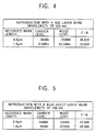
- Fig. 4 shows measurement results of carrier level. noise level and C/N in a case of utilizing a red laser beam having a wavelength of 635nm.
- Fig. 5 shows the same in a case of utilizing a blue-violet laser beam having a wavelength of 406nm.
- a numerical aperture N.A. of an objective lens of measurement apparatus is 0.6
- a track pitch of the magneto-optical recording medium is 0.55 ⁇ m
- recorded mark lengths are 0.4 ⁇ m and 1.6 ⁇ m.
- the inventors of the present invention have finally found a magneto-optical recording medium capable of effectively improving the above-described problems after careful consideration and investigation.
- the present invention provides a magneto-optical recording medium having at least a reproduction layer and a recording layer on a substrate thereof, and on which data-reproduction based on a magnetically induced super-resolution readout method utilizing a blue-violet laser beam is carried out.
- a surface of the substrate being a base surface on which the reproduction layer and the recording layer, that is, recording/reproducing magnetic layers, are formed, or a surface of a dielectric film formed on the substrate (this dielectric film is referred to "first dielectric film” hereinafter) has a surface roughness Ra of 0.3nm or less.
- Ra means an average center roughness defined in JIS B0601, and is merely referred to "surface roughness” in this specification.
- Recording on the magneto-optical recording medium that is, formation of information mark (magnetic domain) according to the present invention can be carried out in accordance with a light intensity modulation or a magnetic field modulation, for example, as in a usual case.
- Reproduction (readout) of the magnetized signal recording on the magneto-optical recording medium is carried out in accordance with the magnetically induced super resolution readout utilizing a blue-violet laser beam, in particular.
- the above-described surface roughness is selected for a preferred structure, which reduces noise, and thus, improves the C/N ratio and the jitter.
- the magneto-optical recording medium according to the present invention is based on the magnetically induced super resolution readout method as its basic principle. However, reproduction or recording/reproduction of the magneto-optical recording medium is carried out by utilizing, in particular, a blue-violet laser beam (that is, a laser beam having a wavelength of 350nm to 450nm).
- a blue-violet laser beam that is, a laser beam having a wavelength of 350nm to 450nm.
- Basic principle of the magnetically induced super resolution readout method being applied to the magneto-optical recording medium of the present invention also includes the following: the CAD-MSR method (the center aperture detection magnetically induced super resolution method) which has previously been cited in the description; the front-aperture detection magnetically induced super resolution method (this will merely be called FAD-MSR in the following description) which is described in Japanese Patent Application Publication Laid-Open HEISEI-9-171643/1997; the rear aperture detection magnetically induced super resolution method (this will merely be called RAD-MSR in the following description) which is described in Japanese Patent Application Publication Laid-Open HEISEI-3-093058/1991 being a basic application of the USP 5,168,482; the domain-wall displacement detection method (this will merely be called DWDD in the following description) which was described in Japanese Patent Application Publication Laid-Open HEISEI-6-290496/1994 being a basic application of the USP 6,027,825; and the magnetic amp
- Such a magnetically induced super resolution readout is carried out on the magneto-optical recording medium according to the present invention, and the laser beam utilized in such a case is in particular the above-described blue-violet laser beam having a short wavelength.
- a base surface on which recording/reproducing magnetic layers having at least a reproduction layer and a recording layer for example, a surface of a substrate of the magneto-optical recording medium, or, in a case where a first dielectric film is formed on the surface, a surface of the first dielectric film is made to have a surface roughness of 0.3nm or less. The value of the surface roughness may be as small as possible if it is 0.3nm or less.
- Recording on the magneto-optical recording medium may be carried out by a conventional recording method and magneto-optical recording apparatus used for a conventional magneto-optical recording medium. For example, a light intensity modulation method or a magnetic field modulation method may be applied.
- An aspect of the present invention is a magneto-optical recording medium on which a reproduction (readout) is carried out in accordance with CAD-MSR utilizing a blue-violet laser beam.
- a magnetized status signal of the reproduction layer is converted into an optical signal by a magneto-optical effect (the Kerr effect or the Faraday effect) to be read out.
- a magneto-optical effect the Kerr effect or the Faraday effect
- the reproduction (readout) method based on the CAD-MSR is carried out as shown in Fig. 3.
- a blue-violet laser beam having a wavelength of 350nm to 450nm is used as a laser beam L.
- Fig. 1 shows a schematic cross-sectional view of an example of the magneto-optical recording medium of the present invention.
- the magneto-optical recording medium of the present invention is applied to the reproduction based on the CAD-MSR method, for example. It should be noted however that the scope of the invention is not solely restricted within the illustrated structures.
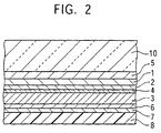
- a first dielectric film 5, a reproduction (readout) layer 1, an auxiliary reproduction layer 2, an non-magnetic intermediate layer 4, a recording layer 3, a second dielectric film 6, and a thermal-control layer 7, are sequentially laminated on a surface of a transparent substrate 10 made of polycarbonate resin, for example. Further, a protection layer 8 is superficially formed by way of covering the top surface thereof.
- the recording layer 3 comprises a first magnetic film 31, a second magnetic film 32 and a third magnetic film 33.
- each of the first, second and third magnetic films 31-33 comprises a rare-earth transition-metal magnetic film whose composition ranges from compensation composition to transition-metal-predominant composition at room temperature.
- the recording layer can be made to have high saturated magnetization in a desired temperature range, in combination of the three magnetic films.
- a transparent substrate 10 having a surface roughness Ra of 0.25nm.
- the surface roughness is measured by an atomic force microscope (AFM).
- the transparent substrate 10 has a diameter of 120mm and a thickness of 0.6mm and also has track grooves (guide grooves) having a track pitch of 0.40 ⁇ m formed thereon.
- the first dielectric film 5, the reproduction layer 1, the auxiliary reproduction layer 2, the non-magnetic intermediate layer 4, the recording layer 3, the second dielectric film 6, and the thermal control layer 7, are sequentially laminated on the transparent substrate 10.
- a protection layer 8 is formed by way of superficially covering the top surface of the thermal control layer 7.
- targets comprising Si, Tb, Gd, FeCo, Fe, and Al are respectively secured to a magnetron sputtering apparatus incorporating a pair of vacuum chambers.
- the transparent substrate 10 is secured to a substrate holder, and then, air remaining in the vacuum chambers is fully evacuated via a cryopump until high vacuum below 1 ⁇ 10 -5 (Pa) is eventually generated.
- valves for feeding argon gas and N 2 gas are respectively closed, and then, the substrate holder is transferred from the first vacuum chamber to the second chamber. Then, air remaining in the second vacuum chamber is fully evacuated by the cryopump until high vacuum below 1 ⁇ 10 -5 (Pa) is eventually generated.
- the reproduction layer 1 of 30nm thick GdFeCo, the auxiliary reproduction layer 2 of 8nm thick GdFe, the non-magnetic intermediate layer 4 of 4nm thick Al, the first magnetic film 31 of 10nm thick GdFeCo of the recording layer 3, the second magnetic film 32 of 30nm thick TbFeCo of the recording layer 3, and the third magnetic film 33 of 30nm thick TbFeCo of the recording layer 3 are sequentially laminated on the first dielectric film 5.
- the valve for feeding argon gas is closed, and then the substrate-holder is transferred from the second vacuum chamber to the first vacuum chamber. Then, while placing the substrate holder inside of the first vacuum chamber, air remaining in the second vacuum chamber is fully evacuated by the cryopump until high vacuum below 1 ⁇ 10 -5 (Pa) is eventually generated.
- valves for feeding argon gas and N 2 gas are respectively closed, and then, air remaining in the first vacuum chamber is fully evacuated by the cryopump until high vacuum below 1 ⁇ 10 -5 (Pa) is eventually generated.
- the thermal control layer 7 of 40nm thick aluminum is formed on the second dielectric film 6.
- composition of each of the above described magnetic layers and metal layers are determined by adjusting the power to be applied on each target.
- the transparent substrate 10 on which the above component films are laminated is drawn out of the vacuum chamber.
- the protection film 8 for protecting the thermal control layer 7 comprising aluminum is formed to be 20 ⁇ m in thickness with ultraviolet-ray-cured resin via coating followed by final curing of the coated resin via irradiation with UV-rays.
- the magneto-optical recording medium is formed.
- the composition of GdFeCo of the reproduction layer 1 is adjusted to show in-plane magnetization at room temperature and perpendicular magnetization at 150°C or more, and to have the Curie temperature of 350°C.
- composition of GdFe of the auxiliary reproduction layer 2 is adjusted to be an in-plane magnetized film of transition-metal-predominant composition from room temperature to the Curie temperature and to have the Curie temperature of 150°C.
- the composition of GdFeCo is adjusted to be a perpendicular magnetized film of transition-metal-predominant composition from room temperature to the Curie temperature and to have the Curie temperature of 300°C.
- the composition of TbFeCo is adjusted to be a perpendicular magnetized film of transition-metal-predominant composition from room temperature to the Curie temperature and to have the Curie temperature of 280°C.
- the composition of TbFeCo is adjusted to be a perpendicular magnetized film of transition-metal-predominant composition from room temperature to the Curie temperature and to have the Curie temperature of 300°C.
- the magneto-optical recording medium will be referred to as an optical disk No. 1 in the following description.
- a magneto-optical recording medium is formed in the same method and structural arrangement of the first embodiment except for the molding condition of the injection molding machine which utilizes a nickel stamper.
- the mold temperature is set to be 135°C and a transparent substrate 10 is made to have a surface roughness Ra of 0.35nm.
- the magneto-optical recording medium will be referred to as an optical disk No. 2 in the following description.
- Both the optical disk No. 1 and the optical disk No. 2 showed good magnetically induced super resolution readout characteristics, in a case where a read laser beam having a wavelength of 635nm is used as a reproducing laser beam in the above-described measurement.
- Fig. 6 shows the results of recording noise level, C/N ratio and jitter measured by a magneto-optical recording/reproducing apparatus using a blue-violet laser beam as described above, with regard to the optical disk No. 1 and the optical disk No. 2.
- the surface roughness is measured with the atomic force microscope (AFM).
- the measured track pitch is 0.40 ⁇ m, as described above, and the jitter is measured at a bit length of 0.19 ⁇ m and the C/N ratio is measured at mark lengths of 0.25 ⁇ m and 1.0 ⁇ m.
- a polycarbonate substrate formed under a molding condition of a mold temperature at 145°C and to have a surface roughness Ra of 0.38nm is prepared.
- the surface roughness of the substrate is changed by ultraviolet irradiation using an ultraviolet lamp.
- "UVO-CLEANER 144A-100” manufactured by Technovision Inc. is used as a UV irradiation apparatus.
- the ultraviolet lamp is a low-pressure mercury grid lamp and has a lamp output of 20mW/cm 2 .
- the main UV wavelengths are 184.4nm and 253.7nm.
- the UV irradiation is carried out in a nitrogen gas atmosphere.
- UV irradiation is carried out on the polycarbonate substrate having the surface roughness of 0.38nm for five minutes to have a surface roughness Ra of 0.25nm.
- the obtained polycarbonate substrate having the surface roughness of 0.25nm is used as the transparent substrate 10.
- the magneto-optical recording medium formed in the same way as the Embodiment 1 with this transparent substrate 10 will be referred to as an optical disk No. 3.
- the embodiment 3 is also based on the method and structural arrangement identical to those which are provided for the Embodiment 2 except for the surface roughness Ra of the transparent substrate 10 being 0.30nm, which is obtained by carrying out the UV irradiation on a polycarbonate substrate having a surface roughness of 0.38nm for five minutes using the UV irradiation apparatus.
- the magneto-optical recording medium of the embodiment 3 will be referred to as an optical disk No. 4 in the following description.
- the comparative example is also based on the method and structural arrangement identical to those provided for the Embodiment 2 except for the surface roughness Ra of the transparent substrate 10 being 0.38nm without UV irradiation.
- the magneto-optical recoding medium of the comparative example 2 will be referred to as an optical disk No. 5.
- Fig. 7 shows the measurement results of reproduction characteristics as described above, with regard to the optical disks No. 3 to No. 5.
- Fig. 7 also shows that the less the surface roughness is, the more the noise level is suppressed. As a result higher C/N ratio and less jitter are measured.
- a polycarbonate substrate formed under a molding condition of a mold temperature at 125°C and to have a surface roughness Ra of 0.30nm is prepared.
- silicon nitride film having a thickness of 40nm is formed on the substrate 10 as the first dielectric film 5.
- the film forming condition is as follows: while evacuating air out from the first vacuum chamber, 50 (sccm) of argon gas and 30 (sccm) of N 2 gas are respectively fed into the first vacuum chamber, and then, a main valve is adjusted until pressure inside of the first vacuum chamber reaches 0.24 (Pa).
- the obtained first dielectric film 5 has a surface roughness Ra of 0.30nm.
- the other method and structural arrangement are identical to those provided for the Embodiment 1.
- the magneto-optical recording medium will be referred to as an optical disk No. 6.
- magneto-optical recording media are formed. These magneto-optical recording media will be referred to as optical disks No. 7 and No. 8, respectively.
- Fig. 8 shows the measurement results of C/N ratio, noise and jitter according to the same measurement method as described above, with regard to the optical disks No. 6 to No. 8.
- the recording layer 3 is a triple-layer structure in the embodiments 1-4, the recording layer 3 may be a single-layer structure as shown in Fig. 2.
- the present invention also provides excellent effect when being used as a magneto-optical recording medium which is subject to magnetically induced super resolution readout process including a process of transferring the recorded mark from the recording layer onto the reproduction layer, such as FAD-MSR, RAD-MSR, or DWDD, or MAMMOS, or the like, for example.
- the objective recording medium comprises at least a reproduction layer and a recording layer comprising multiple layer-built films.
- composition of the layer-components may be subject to a variety of changes or modifications.
- a magneto-optical recording medium improved in its property in C/N ratio, jitter and reproducing power margin, and capable of reproducing signals under the diffraction limit of light excellently, in a case of being subject to magnetically induced super resolution readout capable of reproduction beyond the diffraction limit of light and intending higher density recording by utilizing a blue-violet laser beam.
Abstract
Description
Claims (5)
- A magneto-optical recording medium comprising at least a reproduction layer and a recording layer formed on a substrate, which is subject to a magnetically induced super resolution readout process by irradiation of a blue-violet laser beam, wherein:a surface roughness Ra of said substrate is 0.3nm or less.
- The magneto-optical recording medium according to Claim 1, wherein:said reproduction layer shows in-plane magnetization at room temperature and perpendicular magnetization at 150°C or more; andsaid recording layer comprises a first, second and third magnetic films each made of a rare-earth transition-metal magnetic film being a perpendicular magnetized film having a transition-metal-predominant composition from room temperature to the Curie temperature.
- The magneto-optical recording medium according to Claim 1, wherein UV (ultraviolet) irradiation is carried out on a surface of said substrate to have the surface roughness Ra of 0.3nm or less.
- A magneto-optical recording medium comprising at least a reproduction layer and a recording layer formed on a substrate, which is subject to a magnetically induced super resolution readout process by irradiation of a blue-violet laser beam, wherein:a dielectric film is formed between said substrate and said reproduction layer; anda surface roughness Ra of said dielectric film is 0.3nm or less.
- The magneto-optical recording medium according to Claim 4, wherein:said reproduction layer shows in-plane magnetization at room temperature and perpendicular magnetization at 150°C or more; andsaid recording layer comprises a first, second and third magnetic films each made of a rare-earth transition-metal magnetic film being a perpendicular magnetized film having a transition-metal-predominant composition from room temperature to the Curie temperature.
Applications Claiming Priority (2)
| Application Number | Priority Date | Filing Date | Title |
|---|---|---|---|
| JP30915399A JP2001126328A (en) | 1999-10-29 | 1999-10-29 | Magneto-optical recording medium |
| JP30915399 | 1999-10-29 |
Publications (2)
| Publication Number | Publication Date |
|---|---|
| EP1096486A2 true EP1096486A2 (en) | 2001-05-02 |
| EP1096486A3 EP1096486A3 (en) | 2002-06-12 |
Family
ID=17989567
Family Applications (1)
| Application Number | Title | Priority Date | Filing Date |
|---|---|---|---|
| EP00123269A Withdrawn EP1096486A3 (en) | 1999-10-29 | 2000-10-26 | Magneto-optical recording medium |
Country Status (7)
| Country | Link |
|---|---|
| US (1) | US6638597B1 (en) |
| EP (1) | EP1096486A3 (en) |
| JP (1) | JP2001126328A (en) |
| KR (1) | KR20010060224A (en) |
| CN (1) | CN1301015A (en) |
| ID (1) | ID27923A (en) |
| TW (1) | TW504667B (en) |
Families Citing this family (8)
| Publication number | Priority date | Publication date | Assignee | Title |
|---|---|---|---|---|
| JP4147753B2 (en) | 2001-07-02 | 2008-09-10 | ソニー株式会社 | Optical information recording medium, master for optical information recording medium, and manufacturing method thereof |
| JP2003141787A (en) * | 2001-11-05 | 2003-05-16 | Fujitsu Ltd | Optical recording medium and manufacturing method thereof |
| AU2002219606A1 (en) * | 2002-01-11 | 2003-07-30 | Fujitsu Limited | Optical information recording medium |
| WO2003060897A1 (en) * | 2002-01-11 | 2003-07-24 | Fujitsu Limited | Storage device |
| CN1689081A (en) * | 2002-10-04 | 2005-10-26 | 皇家飞利浦电子股份有限公司 | High track density super resolution MO-ROM medium |
| JP2004185683A (en) * | 2002-11-29 | 2004-07-02 | Sharp Corp | Magnetic recording medium, recording device, and reproducing device |
| US20060000814A1 (en) * | 2004-06-30 | 2006-01-05 | Bo Gu | Laser-based method and system for processing targeted surface material and article produced thereby |
| US7498092B2 (en) * | 2005-01-26 | 2009-03-03 | Hitachi Global Storage Technologies Netherlands B.V. | Perpendicular magnetic recording medium with magnetic torque layer coupled to the perpendicular recording layer |
Family Cites Families (14)
| Publication number | Priority date | Publication date | Assignee | Title |
|---|---|---|---|---|
| JP2957367B2 (en) * | 1993-01-07 | 1999-10-04 | シャープ株式会社 | Magneto-optical recording medium, recording method and recording / reproduction method |
| JPH06231498A (en) * | 1993-02-04 | 1994-08-19 | Idemitsu Petrochem Co Ltd | Magneto-optical recording medium |
| CA2127059A1 (en) * | 1993-07-02 | 1995-01-03 | Masahiko Sekiya | Magneto-optical recording medium |
| JP2799544B2 (en) | 1994-04-28 | 1998-09-17 | 株式会社オハラ | Crystallized glass for information recording disks |
| JPH0817080A (en) * | 1994-04-28 | 1996-01-19 | Mitsubishi Chem Corp | Magneto-optical recording / reproducing method and magneto-optical recording medium used therefor |
| JPH08147782A (en) * | 1994-11-17 | 1996-06-07 | Dainippon Ink & Chem Inc | Magneto-optical recording medium and manufacturing method thereof |
| JPH08221827A (en) * | 1995-02-13 | 1996-08-30 | Hitachi Ltd | Magneto-optical recording medium |
| EP0740296A3 (en) * | 1995-04-26 | 1998-02-25 | Sanyo Electric Co. Ltd | Magneto-optical recording media |
| JP3545133B2 (en) * | 1996-07-23 | 2004-07-21 | シャープ株式会社 | Method of reproducing magneto-optical recording medium and magneto-optical recording medium |
| JPH1064131A (en) * | 1996-08-19 | 1998-03-06 | Fujitsu Ltd | Magneto-optical recording medium and method of manufacturing the same |
| JPH10134435A (en) * | 1996-10-31 | 1998-05-22 | Sony Corp | Magneto-optical recording medium |
| JP3538727B2 (en) * | 1997-10-01 | 2004-06-14 | 富士通株式会社 | Magneto-optical recording medium |
| JP3108397B2 (en) * | 1997-10-13 | 2000-11-13 | 三洋電機株式会社 | Magneto-optical recording medium |
| US6268073B1 (en) * | 1998-11-09 | 2001-07-31 | Seagate Technology Llc | Flash layer overcoat for magnetically-induced super resolution magneto-optical media |
-
1999
- 1999-10-29 JP JP30915399A patent/JP2001126328A/en active Pending
-
2000
- 2000-10-24 TW TW089122317A patent/TW504667B/en not_active IP Right Cessation
- 2000-10-26 EP EP00123269A patent/EP1096486A3/en not_active Withdrawn
- 2000-10-26 US US09/697,473 patent/US6638597B1/en not_active Expired - Fee Related
- 2000-10-27 CN CN00135504A patent/CN1301015A/en active Pending
- 2000-10-30 KR KR1020000063941A patent/KR20010060224A/en not_active Withdrawn
- 2000-10-30 ID IDP20000935A patent/ID27923A/en unknown
Also Published As
| Publication number | Publication date |
|---|---|
| US6638597B1 (en) | 2003-10-28 |
| TW504667B (en) | 2002-10-01 |
| JP2001126328A (en) | 2001-05-11 |
| CN1301015A (en) | 2001-06-27 |
| KR20010060224A (en) | 2001-07-06 |
| ID27923A (en) | 2001-05-03 |
| EP1096486A3 (en) | 2002-06-12 |
Similar Documents
| Publication | Publication Date | Title |
|---|---|---|
| JP3781823B2 (en) | Magneto-optical recording medium and reproducing method thereof | |
| EP0619577B1 (en) | Magneto-optical recording medium and method for reproducing information therein | |
| EP0307554B1 (en) | Amorphous magneto optical recording medium | |
| CN100377241C (en) | Magneto-optical recording medium, method of manufacturing the same, and method for reading the same | |
| US6697323B1 (en) | Optical recording medium and method of manufacturing including smoothing treatment | |
| EP1096486A2 (en) | Magneto-optical recording medium | |
| JPH09180276A (en) | Magneto-optical recording medium and reproducing method thereof | |
| JP3545133B2 (en) | Method of reproducing magneto-optical recording medium and magneto-optical recording medium | |
| US7151716B2 (en) | Magneto-optical recording medium having a transfer control layer | |
| US20040057343A1 (en) | Magnetic recording medium, method for producing the same and magnetic recording/reproducing apparatus | |
| JP2000235743A (en) | Optical memory device and method of manufacturing the same | |
| JP3492233B2 (en) | Magneto-optical recording medium and reproducing method thereof | |
| EP1094455A2 (en) | Magneto-optical recording medium | |
| JP3626050B2 (en) | Magneto-optical recording medium and recording method thereof | |
| US7604878B2 (en) | Magneto-optical recording medium and layer structure | |
| US20030189878A1 (en) | Magneto-optical recording medium having magnetic film formed by sputtering and method of producing same | |
| JP2000222787A (en) | Magneto-optical recording medium | |
| EP1411509A1 (en) | sAGNETO−OPTICAL RECORDING MEDIUM AND ITS PRODUCTION METHOD | |
| US20090103401A1 (en) | Magnetic recording medium, production method for the same, and recording/reproducing method for magnetic medium | |
| US20050028183A1 (en) | Magneto-optical recording medium having in-plane magnetizing layer | |
| US20020022154A1 (en) | Magneto-optical recording medium and process for manufacturing a magneto-optical recording medium | |
| JP2001126331A (en) | Magneto-optical recording medium | |
| HK1041341A (en) | Magnetic-optical recording media | |
| JP2001126329A (en) | Magneto-optical recording medium | |
| JPH08124229A (en) | Magneto-optical recording medium |
Legal Events
| Date | Code | Title | Description |
|---|---|---|---|
| PUAI | Public reference made under article 153(3) epc to a published international application that has entered the european phase |
Free format text: ORIGINAL CODE: 0009012 |
|
| AK | Designated contracting states |
Kind code of ref document: A2 Designated state(s): AT BE CH CY DE DK ES FI FR GB GR IE IT LI LU MC NL PT SE |
|
| AX | Request for extension of the european patent |
Free format text: AL;LT;LV;MK;RO;SI |
|
| PUAL | Search report despatched |
Free format text: ORIGINAL CODE: 0009013 |
|
| AK | Designated contracting states |
Kind code of ref document: A3 Designated state(s): AT BE CH CY DE DK ES FI FR GB GR IE IT LI LU MC NL PT SE |
|
| AX | Request for extension of the european patent |
Free format text: AL;LT;LV;MK;RO;SI |
|
| 17P | Request for examination filed |
Effective date: 20021112 |
|
| AKX | Designation fees paid |
Designated state(s): DE FR GB |
|
| STAA | Information on the status of an ep patent application or granted ep patent |
Free format text: STATUS: THE APPLICATION HAS BEEN WITHDRAWN |
|
| 18W | Application withdrawn |
Effective date: 20031209 |