EP1096206B1 - Low emissions combustor - Google Patents
Low emissions combustor Download PDFInfo
- Publication number
- EP1096206B1 EP1096206B1 EP00309641A EP00309641A EP1096206B1 EP 1096206 B1 EP1096206 B1 EP 1096206B1 EP 00309641 A EP00309641 A EP 00309641A EP 00309641 A EP00309641 A EP 00309641A EP 1096206 B1 EP1096206 B1 EP 1096206B1
- Authority
- EP
- European Patent Office
- Prior art keywords
- heat shield
- flare
- combustor
- cone
- dome
- Prior art date
- Legal status (The legal status is an assumption and is not a legal conclusion. Google has not performed a legal analysis and makes no representation as to the accuracy of the status listed.)
- Expired - Lifetime
Links
Images

Classifications
-
- F—MECHANICAL ENGINEERING; LIGHTING; HEATING; WEAPONS; BLASTING
- F23—COMBUSTION APPARATUS; COMBUSTION PROCESSES
- F23R—GENERATING COMBUSTION PRODUCTS OF HIGH PRESSURE OR HIGH VELOCITY, e.g. GAS-TURBINE COMBUSTION CHAMBERS
- F23R3/00—Continuous combustion chambers using liquid or gaseous fuel
- F23R3/02—Continuous combustion chambers using liquid or gaseous fuel characterised by the air-flow or gas-flow configuration
- F23R3/04—Air inlet arrangements
- F23R3/06—Arrangement of apertures along the flame tube
-
- F—MECHANICAL ENGINEERING; LIGHTING; HEATING; WEAPONS; BLASTING
- F23—COMBUSTION APPARATUS; COMBUSTION PROCESSES
- F23R—GENERATING COMBUSTION PRODUCTS OF HIGH PRESSURE OR HIGH VELOCITY, e.g. GAS-TURBINE COMBUSTION CHAMBERS
- F23R3/00—Continuous combustion chambers using liquid or gaseous fuel
- F23R3/02—Continuous combustion chambers using liquid or gaseous fuel characterised by the air-flow or gas-flow configuration
- F23R3/04—Air inlet arrangements
- F23R3/10—Air inlet arrangements for primary air
- F23R3/12—Air inlet arrangements for primary air inducing a vortex
- F23R3/14—Air inlet arrangements for primary air inducing a vortex by using swirl vanes
-
- Y—GENERAL TAGGING OF NEW TECHNOLOGICAL DEVELOPMENTS; GENERAL TAGGING OF CROSS-SECTIONAL TECHNOLOGIES SPANNING OVER SEVERAL SECTIONS OF THE IPC; TECHNICAL SUBJECTS COVERED BY FORMER USPC CROSS-REFERENCE ART COLLECTIONS [XRACs] AND DIGESTS
- Y02—TECHNOLOGIES OR APPLICATIONS FOR MITIGATION OR ADAPTATION AGAINST CLIMATE CHANGE
- Y02T—CLIMATE CHANGE MITIGATION TECHNOLOGIES RELATED TO TRANSPORTATION
- Y02T50/00—Aeronautics or air transport
- Y02T50/60—Efficient propulsion technologies, e.g. for aircraft
Definitions
- the present invention relates generally to gas turbine engines, and, more specifically, to combustors therein.
- air is pressurized in a compressor and mixed with fuel in a combustor for generating hot combustion gases.
- Energy is extracted from the combustion gases in turbine stages which power the compressor and produce useful work such as powering a fan disposed upstream of the compressor.
- a turbofan engine operates over various power levels at idle, takeoff, and cruise and is designed to maximize efficiency for reducing fuel consumption and undesirable exhaust emissions.
- Typical exhaust emissions include smoke, unburned hydrocarbons, carbon monoxide (CO), and nitrogen oxides (NOx). Due to the complex nature of combustion, and due to the limited space available in typical combustors, many compromises must be made in combustor design for achieving acceptable performance for particular engine designs and power ratings.
- a typical single annular combustor includes radially outer and inner combustion liners joined at forward ends to an annular dome and spaced apart at aft ends to define an annular outlet for discharging combustion gases to the turbines.
- the dome includes a plurality of circumferentially spaced apart carburetors each including a fuel injector and cooperating swirler or swirl cup. Various designs are found for the fuel injectors and the swirlers.
- a typical swirler supports a fuel injector tip and mixes with the fuel therefrom compressed air typically swirled in counter-rotating streams therearound. Air swirling is typically affected by rows of inclined swirl vanes or inclined air holes formed in the body of the swirl cup.
- a fuel and air mixture discharged from each carburetor into the combustor undergoes combustion therein which liberates substantial heat.
- the various components of the combustor are protected from this heat by diverting a portion of the pressurized air for use as cooling air.
- a typical combustion liner is formed of annular panels axially joined together at corresponding film cooling nuggets which create a film of cooling air along the inner surface of the combustor bounding the combustion gases therein.
- Air is also channeled through the dome for cooling thereof.
- the dome is additionally cooled by providing corresponding heat shields or baffles around each of the swirlers which pass through the dome to provide a barrier against the hot combustion gases.
- the heat shields are cooled by holes in the dome which impinge air thereon. The spent impingement air then flows along the heat shields for discharge into the combustor.
- Each swirler also includes an outlet in the form of a flare cone at its aft end which protrudes through a corresponding heat shield.
- the included flare angle of the cone controls the corresponding spray angle of the fuel and air mixture from each of the carburetors.
- flare cones Since the flare cones are directly exposed to the combustion gases, they are subject to heating therefrom. To prevent burning of the flare cone, air may be channeled between the aft side of the heat shield and the front side of the flare cone for providing convection cooling thereof, with the spent air being discharged into the combustor. Combustors including this type of flare cone cooling have been sold in this country for many years. However, this type of flare cone cooling has been found to be a source of hydrocarbon and CO emissions, which are undesirable under more stringent emission requirements.
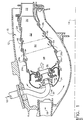
- FIG. 1 Illustrated in Figure 1 is a single annular combustor 10 disposed inside an annular casing 12 in a turbofan gas turbine aircraft engine.
- the combustor is axisymmetrical about a longitudinal or axial centerline axis 14 and receives pressurized air 16 from a compressor (not shown) which is mixed with fuel 18 and ignited for generating hot combustion gases 20 which are discharged from the combustor into conventional turbine stages including a high pressure turbine nozzle 22.
- the combustor includes radially outer and inner annular combustion liners 24,26 joined at forward ends thereof to an annular dome 28, and spaced radially apart at aft ends thereof to define an annular combustor outlet 30.
- a plurality of circumferentially spaced apart carburetors are suitably mounted through the dome, with each including a conventional fuel injector 32 and a cooperating air swirler or swirl cup 34.
- Each swirl cup is suitably mounted to the dome for coaxially receiving a respective fuel injector, and is configured for swirling and mixing air with fuel from the injector for generating a fuel and air mixture which is burned inside the combustor.
- the fuel injector 32 and cooperating swirler 34 may have any conventional configuration.
- the fuel injector 32 preferably has a dual orifice discharge nozzles with primary and secondary fuel circuits.
- the inner primary fuel circuit is sized for idle operation, and the outer secondary circuit is sized for high power operation for hydraulic atomization of the fuel inside the swirler.
- the swirler 34 includes a tubular ferrule 34a which receives the tip of the fuel injector, and includes a row of drilled holes 34b which are axially and circumferentially inclined to swirl primary air in one rotary direction concentrically around the fuel discharged from the injector.
- the swirler also includes a cast tubular body 34c having a row of circumferentially inclined secondary swirl vanes 34d which swirl additional air radially inwardly for discharge axially aft concentrically around the injected fuel and primary swirl air.
- the swirler body 34c also includes a primary venturi 34e disposed coaxially with the fuel injector and ferrule, and a cooperating secondary venturi 34f disposed coaxially with the primary venturi and spaced radially outwardly therefrom for receiving the secondary swirl air therebetween.
- the swirler body 34c is fixedly joined to the combustor dome 28, and the ferrule 34a is joined to the body in a conventional manner for permitting differential radial sliding movement therebetween during operation.
- the injector and swirl cup are conventional in configuration and operation for injecting fuel coaxially inside the swirler and mixing therewith air which is swirled with counter-rotation for producing a fuel and air mixture for undergoing combustion.
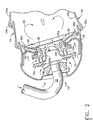
- the swirl cup 34 illustrated in Figure 2 includes a tubular flare cone 36 integrally formed with the secondary venturi 34f in a common casting, for example.
- the flare cone extends axially through a corresponding aperture in the combustor dome 28.
- the flare cone has an obtuse discharge flare angle A for discharging the fuel and air from the swirler in a correspondingly wide spray from the outlet 36a at the aft end of the flare cone.
- a flared heat shield 38 Suitably attached to the dome 28 is a flared heat shield 38 locally surrounding each of the flare cones 36 of each of the swirlers 34 around the circumference of the combustor dome.
- the heat shield 38 is preferably a fabricated sheet metal component which extends in most or major part aft from the flare cone outlet 36a, and is offset in minor part forwardly from the cone outlet 36a to define a radially outwardly facing annular step 40 circumferentially around the outer perimeter of the flare cone at its outlet end.
- the heat shield 38 has a tubular inlet end which is suitably attached inside the dome aperture, by brazing or welding for example.
- the heat shield flares radially outwardly from the flare cone toward the outer and inner liners to shield the combustor dome from the hot combustion gases 20 generated during operation.
- the heat shield also extends circumferentially in opposite directions from swirler to swirler as shown in Figure 3, with the collective circumferential extent of the several heat shields protecting the combustor dome circumferentially inside the combustor.
- the heat shield 38 has an obtuse flare angle B and diverges at least as much as the coaxial flare cone 36.
- the flare cone 36 and heat shield 38 are preferably imperforate at the step 40 in axial section to prevent airflow to the step 40.
- the flare cone 36 and the heat shield 38 are preferably two discrete components unattached to each other at the step 40 to permit unrestrained differential thermal movement therebetween during operation.
- the heat shield 38 is fixedly attached to the combustor dome inside the corresponding aperture therethrough, and the swirler body 34c is fixedly attached to the combustor dome outboard of the secondary swirl vanes 34d, with the secondary venturi 34f and integral flare cone 36 extending axially through the tubular bore of the heat shield inlet.
- the dome and heat shield are cooled in a conventional manner by providing rows of impingement holes 42 through the dome which direct the pressurized air in impingement against the forward side of the heat shield. This air then flows aft along the heat shield for discharge into the combustor.
- the combustor illustrated in Figures 1 and 2 is an improved, larger version of a single annular combustor commercially used in this country for many years. It is sized larger for increasing power from the corresponding engine. However, the larger combustor has a higher attitude starting requirement and is subject to more stringent exhaust emissions requirements. Mere scaling of the combustor to a larger size is insufficient for meeting these requirements.
- the original swirler in the commercial engine includes a sheet metal flare cone extending generally parallel to a cooperating sheet metal heat shield, with both extending coextensively radially outwardly from the centerline of the swirler with corresponding flare angles. Cooling air is injected between the heat shield and flare cone for cooling the flare cone.
- the flare cone 36 is radially truncated relative to the heat shield 38 and terminates at the base of the flared heat shield to define the step 40 therebetween.
- the flare cone 36 is cast with the common swirler body 34c for strength and increased durability, and is preferably a separate component from the surrounding heat shield 38.
- the flare cone and heat shield are assembled so that the cone outlet 36a protrudes aft of the heat shield to effect the step 40. And, no apertures are provided in the region of the step for providing cooling air thereto.
- the step 40 is thusly devoid of cooling air for eliminating undesirable hydrocarbon and CO exhaust emissions produced in the conventional design.
- the obtuse flare angle A of the flare cone provides a wide spray of fuel from the swirler which attaches to the aft surface of the heat shield 38 during operation.
- the attached spray prevents hot gas recirculation around the step 40 for substantially reducing metal temperatures thereat during operation.
- the gases surrounding the step 40 during operation are fuel rich, mostly unburned, and relatively cool, and thusly increase durability and life of this portion of the combustor.
- the wide spray from the flare cone also reduces unburned hydrocarbon emissions during operation, and additionally improves altitude starting.
- the flare angles A,B of both the flare cone 36 and heat shield 38 are preferably greater than about 110°, and preferably about 120°. In this way, a wide spray pattern is effected for attachment to the heat shield for the advantages described above.
- the combustor illustrated in Figure 1 is relatively small for powering a small turbofan engine in the 9,000-18,000 pound thrust range.
- relatively narrow and acute flare cone angles are used for proper operation of the combustors.
- narrow spray severely compromises altitude starting and is thusly undesirable.
- the wide spray operation of the swirler shown in Figure 1 not only increases altitude starting capability in the small combustor, but cooperates with the step 40 and heat shield for maintaining attachment of the gas mixture from the swirlers along the heat shield for reducing exhaust emissions while providing a cooling mechanism in this region.
- the step 40 illustrated in Figure 2 is sufficiently small for permitting gas discharge from the flare cone to attach to the heat shield, as well as stabilizing the flow attachment thereto.
- An additional advantage of the separate, but cooperating flare cone 36 and heat shield 38 is the substantial reduction in thermally generated stress during operation. During operation, a substantial temperature gradient is effected along the secondary venturi 34f to the flare cone 36 at the aft end thereof and along the heat shield 38. The heat shield 38 is relatively hot as compared with the flare cone 36.
- the heat shield 38 may be conventionally formed from stamped sheet metal having fast thermal response during operation.
- the flare cone 36 is preferably cast with the common swirler body 34c for increasing its strength and durability.
- the heat shield 38 includes an aft perimeter or boundary having radially opposite outer and inner circumferentially extending border edges 38a, and circumferentially opposite, radially extending lateral edges 38b having a generally rectangular configuration.
- the lateral edges 38b are preferably arcuate or rolled forward to adjoin the combustor dome 28 and restrict airflow therebetween.
- border edges 38a are arcuate or rolled aft toward the corresponding outer and inner liners 24,26, as additionally illustrated in Figure 2.
- the heat shield 38 thusly combines both rolled border and lateral edges, which rolled edges are conventional in double annular combustors, but not previously applied in a single annular combustor of the type illustrated in Figure 1.
- the rolling of the lateral edges 38b restricts or prevents cooling air discharge along those edges circumferentially between adjacent swirl cups, and instead directs all or most of the spent impingement cooling air in two paths radially outwardly to the outer liner 24 and radially inwardly to the inner liner 26.
- This feature in combination with the flare cone step 40 provides significant improvement in altitude starting, and a significant reduction in unburned hydrocarbon emissions.
- the rolled border edges 38a better direct the spent impingement air along the corresponding outer and inner liners 24,26 to provide additional film cooling thereof.
- each of the outer and inner combustor liners 24,26 illustrated in Figures 1 and 2 is preferably formed of annular panels or segments 24a,26a axially joined together at corresponding film cooling nuggets 24b,26b in a conventional manner.
- Each nugget includes one or more rows of film cooling holes which channel the pressurized air 16 as films along the inside surface of the liners exposed to the combustion gases.
- each liner is preferably formed of five axially adjoining panels 24a,26a which is one more panel than found in the conventional combustor over which the present invention is an improvement in larger size.
- the second and third panels 24a,26a of the two liners aft from the dome 28 include first and second respective rows of dilution holes 44,46 which inject into the combustor substantial portions of the pressurized air 16 for diluting the combustion gases generated therein.
- the two rows of dilution holes 44,46 illustrated in Figure 1 divide the combustor into a primary combustion zone 48 between the dome 28 and the first dilution row, an intermediate zone 50 axially between the first and second dilution rows, and an aft zone 52 axially between the second dilution row and the combustor outlet 30.
- Dilution holes are conventionally found in combustors in various configurations.
- the combustor illustrated in Figure 1 preferably has five liner panels which is one more than the conventional combustor over which the present combustor is an improvement.
- the dilution holes are positioned in the second and third liner panels with there being only single liner panels upstream therefrom and downstream therefrom. That combination affects the overall performance of the combustor.
- the dilution holes are also positioned in the second and third liner panels, but the combustor has a larger volume, and includes two liner panels aft of the second dilution row which significantly alters the relative sizes of the three combustion zones.
- the primary zone 40 is sized to have the maximum burning volume of the three zones, and the intermediate zone 50 is sized to have the minimum volume.
- the primary zone 48 cooperates with the row of swirl cups 34 in the dome 28 for receiving combustor air primarily only therefrom.
- first dilution row at the second liner panels provides a relatively large primary burning volume which minimizes entrainment of first row dilution air into the primary zone. This works in concert with the above described wide spray distribution from the row of swirl cups.
- the counter-rotating swirl cups 34 mix well the fuel and air for allowing acceptable levels of smoke despite a relatively rich condition in the primary zone at takeoff power.
- the homogeneous rich mixture in the primary zone also suppresses NOx formation therein.
- Swirler airflow is preferably set to provide near stoichiometric conditions in the primary zone at ground idle settings to minimize emissions of CO and unburned hydrocarbons. At high power, the primary zone runs sufficiently rich to suppress NOx formation.
- the first row of dilution holes 44 is preferably sized to dilute the combustion gases to a slightly lean condition or equivalence ratio at high power to maximize CO burnout.
- the second row of dilution holes 46 is close coupled to the first row by being disposed in the next downstream liner panel, and is sized to provide rapid quenching of the lean combustion gases to minimize NOx formation.
- the configuration of the combustor illustrated in Figure 1 thusly provides the many benefits of a rich-lean-quick quench combustor providing low NOx and CO emissions, but not at the expense of altitude starting requirements.
- the primary zone 48 may be operated fuel rich to the degree which allows acceptable levels of smoke.
- the intermediate zone 50 in which dilution air is first injected transitions the combustion gases from rich to lean and is a region of NOx formation.
- the aft zone 52 is the final mixing zone of the dilution air with the combustion gases prior to entering the turbine.
- the improved flare cone 36 and heat shield 38 combination described above provide yet further benefits.
- the primary combustion zone 38 may be operated relatively rich, with rich, primarily unburned gases attaching to the heat shield 38 during operation for providing effective cooling thereof while minimizing exhaust emissions.
- the spent impingement air from the heat shields is directed to the first liner panels to provide additional cooling thereof. This increased cooling effectiveness of the spent heat shield cooling air improves durability of the first liner panel, and reduces the cooling air requirement therefor from the film cooling nuggets.
- the reduced cooling air from the first cooling nugget further reduces emissions of CO and unburned hydrocarbons.
- the wide angle flare cone 36 and forward rolled heat shield border edges 38a not only increase the altitude starting ceiling, but improve performance of the combustor. Accordingly, for a given power rating of the combustor, it may be configured with a smaller burning volume for a unit airflow than otherwise possible. This relatively smaller burning volume reduces residence time for the combustion gases therein and reduces NOx emissions. The correspondingly smaller overall combustor size made possible by the reduced burning volume also requires less airflow for dome and liner cooling, which further reduces CO emissions and unburned hydrocarbons, while maintaining acceptable liner life and combustion gas exit temperature distribution in the circumferential pattern factor and radial profile factor.
- an otherwise conventional swirl cup to include the wide angle flare cone 36 and cooperating heat shield 38 having the step 40 therebetween permits substantial improvement in single annular combustor design in a small combustor not otherwise possible.
- the combustor illustrated in Figures 1-3 additionally includes otherwise conventional components in a new and synergistic combination for enhancing combustor performance with relatively high altitude starting capability, with reduced exhaust emissions, and with enhanced durability and life.
Landscapes
- Engineering & Computer Science (AREA)
- Chemical & Material Sciences (AREA)
- Combustion & Propulsion (AREA)
- Mechanical Engineering (AREA)
- General Engineering & Computer Science (AREA)
Applications Claiming Priority (2)
| Application Number | Priority Date | Filing Date | Title |
|---|---|---|---|
| US431464 | 1999-11-01 | ||
| US09/431,464 US6279323B1 (en) | 1999-11-01 | 1999-11-01 | Low emissions combustor |
Publications (2)
| Publication Number | Publication Date |
|---|---|
| EP1096206A1 EP1096206A1 (en) | 2001-05-02 |
| EP1096206B1 true EP1096206B1 (en) | 2006-08-09 |
Family
ID=23712059
Family Applications (1)
| Application Number | Title | Priority Date | Filing Date |
|---|---|---|---|
| EP00309641A Expired - Lifetime EP1096206B1 (en) | 1999-11-01 | 2000-11-01 | Low emissions combustor |
Country Status (4)
| Country | Link |
|---|---|
| US (1) | US6279323B1 (nl) |
| EP (1) | EP1096206B1 (nl) |
| JP (1) | JP4659201B2 (nl) |
| DE (1) | DE60029897T2 (nl) |
Cited By (1)
| Publication number | Priority date | Publication date | Assignee | Title |
|---|---|---|---|---|
| CN110657452A (zh) * | 2018-06-29 | 2020-01-07 | 中国航发商用航空发动机有限责任公司 | 低污染燃烧室及其燃烧控制方法 |
Families Citing this family (50)
| Publication number | Priority date | Publication date | Assignee | Title |
|---|---|---|---|---|
| US6655146B2 (en) * | 2001-07-31 | 2003-12-02 | General Electric Company | Hybrid film cooled combustor liner |
| US20030229559A1 (en) * | 2002-04-09 | 2003-12-11 | Panttaja James T. | Asset management platform |
| US6725667B2 (en) * | 2002-08-22 | 2004-04-27 | General Electric Company | Combustor dome for gas turbine engine |
| US6834505B2 (en) * | 2002-10-07 | 2004-12-28 | General Electric Company | Hybrid swirler |
| DE10257704A1 (de) * | 2002-12-11 | 2004-07-15 | Alstom Technology Ltd | Verfahren zur Verbrennung eines Brennstoffs |
| US20040202977A1 (en) * | 2003-04-08 | 2004-10-14 | Ken Walkup | Low NOx burner |
| FR2856468B1 (fr) * | 2003-06-17 | 2007-11-23 | Snecma Moteurs | Chambre de combustion annulaire de turbomachine |
| US6986253B2 (en) * | 2003-07-16 | 2006-01-17 | General Electric Company | Methods and apparatus for cooling gas turbine engine combustors |
| EP1510761A1 (de) * | 2003-08-13 | 2005-03-02 | Siemens Aktiengesellschaft | Verfahren zur Verbrennung eines fluidischen Brennstoffs sowie Brenner, insbesondere für eine Gasturbine, zur Durchführung des Verfahrens |
| US7185497B2 (en) * | 2004-05-04 | 2007-03-06 | Honeywell International, Inc. | Rich quick mix combustion system |
| US7013649B2 (en) * | 2004-05-25 | 2006-03-21 | General Electric Company | Gas turbine engine combustor mixer |
| US7308794B2 (en) * | 2004-08-27 | 2007-12-18 | Pratt & Whitney Canada Corp. | Combustor and method of improving manufacturing accuracy thereof |
| US7246494B2 (en) * | 2004-09-29 | 2007-07-24 | General Electric Company | Methods and apparatus for fabricating gas turbine engine combustors |
| US7421843B2 (en) * | 2005-01-15 | 2008-09-09 | Siemens Power Generation, Inc. | Catalytic combustor having fuel flow control responsive to measured combustion parameters |
| US7386980B2 (en) * | 2005-02-02 | 2008-06-17 | Power Systems Mfg., Llc | Combustion liner with enhanced heat transfer |
| US7316117B2 (en) * | 2005-02-04 | 2008-01-08 | Siemens Power Generation, Inc. | Can-annular turbine combustors comprising swirler assembly and base plate arrangements, and combinations |
| US7513098B2 (en) | 2005-06-29 | 2009-04-07 | Siemens Energy, Inc. | Swirler assembly and combinations of same in gas turbine engine combustors |
| US7464553B2 (en) * | 2005-07-25 | 2008-12-16 | General Electric Company | Air-assisted fuel injector for mixer assembly of a gas turbine engine combustor |
| FR2894327B1 (fr) * | 2005-12-05 | 2008-05-16 | Snecma Sa | Dispositif d'injection d'un melange d'air et de carburant, chambre de combustion et turbomachine munies d'un tel dispositif |
| FR2906350B1 (fr) * | 2006-09-22 | 2009-03-20 | Snecma Sa | Chambre de combustion annulaire d'une turbomachine |
| FR2908867B1 (fr) * | 2006-11-16 | 2012-06-15 | Snecma | Dispositif d'injection d'un melange d'air et de carburant, chambre de combustion et turbomachine munies d'un tel dispositif |
| US8707704B2 (en) * | 2007-05-31 | 2014-04-29 | General Electric Company | Method and apparatus for assembling turbine engines |
| FR2921462B1 (fr) * | 2007-09-21 | 2012-08-24 | Snecma | Chambre de combustion annulaire de moteur a turbine a gaz |
| US20090165435A1 (en) * | 2008-01-02 | 2009-07-02 | Michal Koranek | Dual fuel can combustor with automatic liquid fuel purge |
| US8096132B2 (en) * | 2008-02-20 | 2012-01-17 | Flexenergy Energy Systems, Inc. | Air-cooled swirlerhead |
| US20090255118A1 (en) * | 2008-04-11 | 2009-10-15 | General Electric Company | Method of manufacturing mixers |
| US8281597B2 (en) * | 2008-12-31 | 2012-10-09 | General Electric Company | Cooled flameholder swirl cup |
| US8443610B2 (en) * | 2009-11-25 | 2013-05-21 | United Technologies Corporation | Low emission gas turbine combustor |
| FR2955375B1 (fr) * | 2010-01-18 | 2012-06-15 | Turbomeca | Dispositif d'injection et chambre de combustion de turbomachine equipee d'un tel dispositif d'injection |
| GB201116608D0 (en) * | 2011-09-27 | 2011-11-09 | Rolls Royce Plc | A method of operating a combustion chamber |
| US10378775B2 (en) * | 2012-03-23 | 2019-08-13 | Pratt & Whitney Canada Corp. | Combustor heat shield |
| US9021812B2 (en) | 2012-07-27 | 2015-05-05 | Honeywell International Inc. | Combustor dome and heat-shield assembly |
| US9803498B2 (en) | 2012-10-17 | 2017-10-31 | United Technologies Corporation | One-piece fuel nozzle for a thrust engine |
| EP2920519A1 (en) * | 2012-11-15 | 2015-09-23 | General Electric Company | Fuel nozzle heat shield |
| US10260748B2 (en) | 2012-12-21 | 2019-04-16 | United Technologies Corporation | Gas turbine engine combustor with tailored temperature profile |
| WO2014123850A1 (en) | 2013-02-06 | 2014-08-14 | United Technologies Corporation | Gas turbine engine component with upstream-directed cooling film holes |
| EP2954261B1 (en) | 2013-02-08 | 2020-03-04 | United Technologies Corporation | Gas turbine engine combustor |
| US10914470B2 (en) | 2013-03-14 | 2021-02-09 | Raytheon Technologies Corporation | Combustor panel with increased durability |
| JP6470135B2 (ja) | 2014-07-14 | 2019-02-13 | ユナイテッド テクノロジーズ コーポレイションUnited Technologies Corporation | 付加製造された表面仕上げ |
| BR112017011472B1 (pt) | 2014-12-15 | 2022-09-13 | Nuovo Pignone Tecnologie Srl | Combustor para uma turbina a gás e método para montar um forro de combustor |
| US10309654B2 (en) * | 2016-07-27 | 2019-06-04 | Honda Motor Co., Ltd. | Structure for cooling gas turbine engine |
| US10816202B2 (en) | 2017-11-28 | 2020-10-27 | General Electric Company | Combustor liner for a gas turbine engine and an associated method thereof |
| FR3082284B1 (fr) * | 2018-06-07 | 2020-12-11 | Safran Aircraft Engines | Chambre de combustion pour une turbomachine |
| US11255543B2 (en) | 2018-08-07 | 2022-02-22 | General Electric Company | Dilution structure for gas turbine engine combustor |
| CN111829012B (zh) * | 2019-04-17 | 2022-04-08 | 中国航发湖南动力机械研究所 | 火焰筒 |
| US11719438B2 (en) * | 2021-03-15 | 2023-08-08 | General Electric Company | Combustion liner |
| US11859819B2 (en) | 2021-10-15 | 2024-01-02 | General Electric Company | Ceramic composite combustor dome and liners |
| US12072099B2 (en) * | 2021-12-21 | 2024-08-27 | General Electric Company | Gas turbine fuel nozzle having a lip extending from the vanes of a swirler |
| US11774100B2 (en) * | 2022-01-14 | 2023-10-03 | General Electric Company | Combustor fuel nozzle assembly |
| US12092324B2 (en) * | 2022-03-17 | 2024-09-17 | General Electric Company | Flare cone for a mixer assembly of a gas turbine combustor |
Family Cites Families (18)
| Publication number | Priority date | Publication date | Assignee | Title |
|---|---|---|---|---|
| US3853273A (en) * | 1973-10-01 | 1974-12-10 | Gen Electric | Axial swirler central injection carburetor |
| GB1595224A (en) * | 1977-02-04 | 1981-08-12 | Rolls Royce | Combustion equipment for gas turbine engines |
| US4180974A (en) * | 1977-10-31 | 1980-01-01 | General Electric Company | Combustor dome sleeve |
| US4315405A (en) * | 1978-12-09 | 1982-02-16 | Rolls-Royce Limited | Combustion apparatus |
| EP0153842B1 (en) * | 1984-02-29 | 1988-07-27 | LUCAS INDUSTRIES public limited company | Combustion equipment |
| DE3545524C2 (de) * | 1985-12-20 | 1996-02-29 | Siemens Ag | Mehrstufenbrennkammer für die Verbrennung von stickstoffhaltigem Gas mit verringerter NO¶x¶-Emission und Verfahren zu ihrem Betrieb |
| US5481867A (en) * | 1988-05-31 | 1996-01-09 | United Technologies Corporation | Combustor |
| US5117637A (en) * | 1990-08-02 | 1992-06-02 | General Electric Company | Combustor dome assembly |
| DE4110507C2 (de) | 1991-03-30 | 1994-04-07 | Mtu Muenchen Gmbh | Brenner für Gasturbinentriebwerke mit mindestens einer für die Zufuhr von Verbrennungsluft lastabhängig regulierbaren Dralleinrichtung |
| IT1273369B (it) * | 1994-03-04 | 1997-07-08 | Nuovo Pignone Spa | Sistema perfezionato combustione a basse emissioni inquinanti per turbine a gas |
| EP0678708B1 (en) | 1994-04-20 | 1998-12-02 | ROLLS-ROYCE plc | Gas turbine engine fuel injector |
| FR2751054B1 (fr) | 1996-07-11 | 1998-09-18 | Snecma | Chambre de combustion anti-nox a injection de carburant de type annulaire |
| FR2753779B1 (fr) * | 1996-09-26 | 1998-10-16 | Systeme d'injection aerodynamique d'un melange air carburant | |
| US5970716A (en) * | 1997-10-02 | 1999-10-26 | General Electric Company | Apparatus for retaining centerbody between adjacent domes of multiple annular combustor employing interference and clamping fits |
| FR2770283B1 (fr) * | 1997-10-29 | 1999-11-19 | Snecma | Chambre de combustion pour turbomachine |
| US6550251B1 (en) * | 1997-12-18 | 2003-04-22 | General Electric Company | Venturiless swirl cup |
| US6240731B1 (en) * | 1997-12-31 | 2001-06-05 | United Technologies Corporation | Low NOx combustor for gas turbine engine |
| US6101814A (en) * | 1999-04-15 | 2000-08-15 | United Technologies Corporation | Low emissions can combustor with dilution hole arrangement for a turbine engine |
-
1999
- 1999-11-01 US US09/431,464 patent/US6279323B1/en not_active Expired - Lifetime
-
2000
- 2000-10-31 JP JP2000331593A patent/JP4659201B2/ja not_active Expired - Fee Related
- 2000-11-01 EP EP00309641A patent/EP1096206B1/en not_active Expired - Lifetime
- 2000-11-01 DE DE60029897T patent/DE60029897T2/de not_active Expired - Lifetime
Cited By (3)
| Publication number | Priority date | Publication date | Assignee | Title |
|---|---|---|---|---|
| CN110657452A (zh) * | 2018-06-29 | 2020-01-07 | 中国航发商用航空发动机有限责任公司 | 低污染燃烧室及其燃烧控制方法 |
| CN110657452B (zh) * | 2018-06-29 | 2020-10-27 | 中国航发商用航空发动机有限责任公司 | 低污染燃烧室及其燃烧控制方法 |
| US11506387B2 (en) | 2018-06-29 | 2022-11-22 | Aecc Commercial Aircraft Engine Co., Ltd. | Low-pollution combustor and combustion control method therefor |
Also Published As
| Publication number | Publication date |
|---|---|
| EP1096206A1 (en) | 2001-05-02 |
| JP2001147018A (ja) | 2001-05-29 |
| DE60029897T2 (de) | 2007-03-08 |
| JP4659201B2 (ja) | 2011-03-30 |
| US6279323B1 (en) | 2001-08-28 |
| DE60029897D1 (de) | 2006-09-21 |
Similar Documents
| Publication | Publication Date | Title |
|---|---|---|
| EP1096206B1 (en) | Low emissions combustor | |
| EP1333228B1 (en) | Method and apparatus to decrease combustor emissions | |
| EP1096205B1 (en) | Offset dilution combustion liner | |
| EP1429078B1 (en) | Apparatus for decreasing gas turbine engine combustor emissions | |
| EP1262718B1 (en) | Method and apparatus for mixing fuel to decrease combustor emissions | |
| JP4632392B2 (ja) | 噴霧パイロットを有する多重環状燃焼チャンバスワーラ | |
| EP1167881B1 (en) | Methods and apparatus for decreasing combustor emissions with swirl stabilized mixer | |
| EP1262719B1 (en) | Method and apparatus for controlling combustor emissions | |
| US6415594B1 (en) | Methods and apparatus for reducing gas turbine engine emissions | |
| US8281597B2 (en) | Cooled flameholder swirl cup | |
| EP1193447B1 (en) | Multiple injector combustor | |
| EP1167882B1 (en) | Methods and apparatus for decreasing combustor emissions with spray bar assembly | |
| JP2000320836A (ja) | 燃料インジェクタ及び燃料と空気の噴射方法 | |
| EP1426690B1 (en) | Apparatus to decrease combustor emissions |
Legal Events
| Date | Code | Title | Description |
|---|---|---|---|
| PUAI | Public reference made under article 153(3) epc to a published international application that has entered the european phase |
Free format text: ORIGINAL CODE: 0009012 |
|
| AK | Designated contracting states |
Kind code of ref document: A1 Designated state(s): DE FR GB IT |
|
| AX | Request for extension of the european patent |
Free format text: AL;LT;LV;MK;RO;SI |
|
| 17P | Request for examination filed |
Effective date: 20011102 |
|
| AKX | Designation fees paid |
Free format text: DE FR GB IT |
|
| 17Q | First examination report despatched |
Effective date: 20040806 |
|
| GRAP | Despatch of communication of intention to grant a patent |
Free format text: ORIGINAL CODE: EPIDOSNIGR1 |
|
| GRAS | Grant fee paid |
Free format text: ORIGINAL CODE: EPIDOSNIGR3 |
|
| GRAA | (expected) grant |
Free format text: ORIGINAL CODE: 0009210 |
|
| AK | Designated contracting states |
Kind code of ref document: B1 Designated state(s): DE FR GB IT |
|
| PG25 | Lapsed in a contracting state [announced via postgrant information from national office to epo] |
Ref country code: IT Free format text: LAPSE BECAUSE OF FAILURE TO SUBMIT A TRANSLATION OF THE DESCRIPTION OR TO PAY THE FEE WITHIN THE PRESCRIBED TIME-LIMIT;WARNING: LAPSES OF ITALIAN PATENTS WITH EFFECTIVE DATE BEFORE 2007 MAY HAVE OCCURRED AT ANY TIME BEFORE 2007. THE CORRECT EFFECTIVE DATE MAY BE DIFFERENT FROM THE ONE RECORDED. Effective date: 20060809 |
|
| REG | Reference to a national code |
Ref country code: GB Ref legal event code: FG4D |
|
| REF | Corresponds to: |
Ref document number: 60029897 Country of ref document: DE Date of ref document: 20060921 Kind code of ref document: P |
|
| ET | Fr: translation filed | ||
| PLBE | No opposition filed within time limit |
Free format text: ORIGINAL CODE: 0009261 |
|
| STAA | Information on the status of an ep patent application or granted ep patent |
Free format text: STATUS: NO OPPOSITION FILED WITHIN TIME LIMIT |
|
| 26N | No opposition filed |
Effective date: 20070510 |
|
| REG | Reference to a national code |
Ref country code: FR Ref legal event code: PLFP Year of fee payment: 16 |
|
| PGFP | Annual fee paid to national office [announced via postgrant information from national office to epo] |
Ref country code: GB Payment date: 20151127 Year of fee payment: 16 Ref country code: DE Payment date: 20151127 Year of fee payment: 16 Ref country code: IT Payment date: 20151124 Year of fee payment: 16 |
|
| PGFP | Annual fee paid to national office [announced via postgrant information from national office to epo] |
Ref country code: FR Payment date: 20151117 Year of fee payment: 16 |
|
| REG | Reference to a national code |
Ref country code: DE Ref legal event code: R119 Ref document number: 60029897 Country of ref document: DE |
|
| GBPC | Gb: european patent ceased through non-payment of renewal fee |
Effective date: 20161101 |
|
| REG | Reference to a national code |
Ref country code: FR Ref legal event code: ST Effective date: 20170731 |
|
| PG25 | Lapsed in a contracting state [announced via postgrant information from national office to epo] |
Ref country code: FR Free format text: LAPSE BECAUSE OF NON-PAYMENT OF DUE FEES Effective date: 20161130 Ref country code: IT Free format text: LAPSE BECAUSE OF NON-PAYMENT OF DUE FEES Effective date: 20161101 |
|
| PG25 | Lapsed in a contracting state [announced via postgrant information from national office to epo] |
Ref country code: GB Free format text: LAPSE BECAUSE OF NON-PAYMENT OF DUE FEES Effective date: 20161101 Ref country code: DE Free format text: LAPSE BECAUSE OF NON-PAYMENT OF DUE FEES Effective date: 20170601 |