EP1096195A1 - Hose connecting structure - Google Patents
Hose connecting structure Download PDFInfo
- Publication number
- EP1096195A1 EP1096195A1 EP00123010A EP00123010A EP1096195A1 EP 1096195 A1 EP1096195 A1 EP 1096195A1 EP 00123010 A EP00123010 A EP 00123010A EP 00123010 A EP00123010 A EP 00123010A EP 1096195 A1 EP1096195 A1 EP 1096195A1
- Authority
- EP
- European Patent Office
- Prior art keywords
- hose
- pipe
- corner
- set forth
- projection
- Prior art date
- Legal status (The legal status is an assumption and is not a legal conclusion. Google has not performed a legal analysis and makes no representation as to the accuracy of the status listed.)
- Granted
Links
Images



Classifications
-
- F—MECHANICAL ENGINEERING; LIGHTING; HEATING; WEAPONS; BLASTING
- F16—ENGINEERING ELEMENTS AND UNITS; GENERAL MEASURES FOR PRODUCING AND MAINTAINING EFFECTIVE FUNCTIONING OF MACHINES OR INSTALLATIONS; THERMAL INSULATION IN GENERAL
- F16L—PIPES; JOINTS OR FITTINGS FOR PIPES; SUPPORTS FOR PIPES, CABLES OR PROTECTIVE TUBING; MEANS FOR THERMAL INSULATION IN GENERAL
- F16L37/00—Couplings of the quick-acting type
- F16L37/02—Couplings of the quick-acting type in which the connection is maintained only by friction of the parts being joined
- F16L37/04—Couplings of the quick-acting type in which the connection is maintained only by friction of the parts being joined with an elastic outer part pressing against an inner part by reason of its elasticity
-
- F—MECHANICAL ENGINEERING; LIGHTING; HEATING; WEAPONS; BLASTING
- F16—ENGINEERING ELEMENTS AND UNITS; GENERAL MEASURES FOR PRODUCING AND MAINTAINING EFFECTIVE FUNCTIONING OF MACHINES OR INSTALLATIONS; THERMAL INSULATION IN GENERAL
- F16L—PIPES; JOINTS OR FITTINGS FOR PIPES; SUPPORTS FOR PIPES, CABLES OR PROTECTIVE TUBING; MEANS FOR THERMAL INSULATION IN GENERAL
- F16L33/00—Arrangements for connecting hoses to rigid members; Rigid hose-connectors, i.e. single members engaging both hoses
- F16L33/30—Arrangements for connecting hoses to rigid members; Rigid hose-connectors, i.e. single members engaging both hoses comprising parts inside the hoses only
Definitions
- This invention relates to a hose connecting structure obtained by press fitting a hard pipe into a flexible hose, such as of rubber, while expanding the latter radially to a certain extent.
- This type of structure is often employed for connecting, for example, hoses and a branched hard pipe in an automobile engine compartment.
- Japanese Patent Application Laid-Open No. 331894/1992 discloses a hard pipe 6 having stoppers 5 formed on its outer periphery by exchange mold injection from a soft material, and pressed fitted in a flexible hose 7, as shown in FIG. 2.
- Japanese Patent Application Laid-Open No. 331894/1992 discloses a hard pipe 6 having stoppers 5 formed on its outer periphery by exchange mold injection from a soft material, and pressed fitted in a flexible hose 7, as shown in FIG. 2.
- a branched pipe 8 of a hard material having three branches 9 each having formed on its outer periphery stop ridges 10 each having a cross section terminating in a sharp edge, each branch 9 being press fitted in a flexible hose 12 having a reinforcing fiber layer 11 in its wall, as shown in FIG. 3.
- a hose connecting structure comprising a flexible hose having a reinforcing fiber layer in its wall, and a hard pipe a portion of which is press fitted in the hose, wherein the pipe has an annular stop projection formed about its press fitted portion, and having a cross sectional contour including a gentle outward slope from the front end of the projection toward the rear end side to a first corner, which makes the angle of the subsequent second corner gentle, and a rear face at this second corner extending inward toward the longitudinal axis of the pipe at right angles thereto, forming an annular depression.
- the structure can be made with high working efficiency using a method in which the hard pipe is press fitted into the flexible hose while the hose is radially expanded. Even if a strong pull-out force may act upon the assembly, the stop projection forming an integral part of the pipe does not come off, or become displaced, but the assembly maintains its pull-out strength and sealing properties.
- the hose 15 has a reinforcing fiber layer 18 in its wall.
- the reinforcing fiber layer 18 does not, however, present any resistance to the press fitting of the pipe 13, since the hose 15 is radially expanded when the pipe 13 is press fitted therein, as is obvious from (1) above, If a pull-out force acts upon the structure, the hose 15 is caused to contract radially, and the reinforcing fiber layer 18 holds the inner surface of the hose 15 strongly against the stop projection 14 to enhance the pull-out strength of the assembly, as is obvious from (2) above. It is, however, possible to avoid any damaging of the hose 15, as is obvious from (3) above.
- the hose is radially expanded by at least 20% when the pipe is press fitted thereinto.
- the radial expansion of the hose to such an extent ensures the still higher pull-out strength and sealing properties of the assembly, while it is still possible to avoid any damaging of the hose by the stop projection on the pipe and any resulting lowering of sealing properties, as explained above.
- At least an innermost wall layer of the hose is formed from an elastomer having a tear strength of at least 20 N/mm, such as EPDM (an ethylene-propylene-diene terpolymer) or EPM (an ethylene-propylene copolymer).
- EPDM an ethylene-propylene-diene terpolymer
- EPM an ethylene-propylene copolymer
- the reinforcing fiber layer has a pull-out strength of at least 0.3 N/mm.
- the radial expansion of the hose by a very high percentage may cause the separation of the reinforcing fiber layer from the wall of the hose or its displacement and thereby lower the sealing properties of the assembly.
- no such separation or displacement is likely to occur to any hose with a reinforcing layer having a pull-out strength of at least 0.3 N/mm.
- the hose connecting structure of this invention can be employed for connecting a hose to a pipe in any field of art.
- a typical example of its application is, however, the joining of a hose to a radiator, or heater in an automobile engine compartment.
- the pipe may be of the branched or non-branched type.
- the hard pipe may be a branched or non-branched one having an annular stop projection formed about the portion press fitted in the hose.
- the pipe may, for example, be of hard nylon, such as nylon 6 or 66, reinforced or not reinforced with glass fiber, though it may be of any other appropriate material.
- FIG. 5 shows by way of example a branched hard pipe 19 having three branches 20 formed each for fitting in a hose.
- Each branch 20 has an annular stop projection 21 formed thereabout as an integral part thereof.
- Each projection 21 has a height depending on factors including the percentage by which the hose is radially expanded when the branch 20 is press fitted thereinto.
- Each projection 21 has a cross sectional contour including a gentle slope extending from the front end of the projection 21 toward the rear end side to a first corner 22a, and a second corner 22b at the rear end of the projection 21. Due to the first corner 22a, the angle at the second corner 22b is enlarged. The rear face at the second corner 22b extends inward at right angles to the longitudinal axis of the pipe, creating an annular depression.
- the cross sectional contour of the projection 21 as described is more clearly shown in FIG. 6A.
- the first corner 22a has such an angle that the top face of the projection 21 may be parallel to a line x parallel to the longitudinal axis of the pipe 19, and that the second corner 22b may have an angle of 90°.
- FIG. 6B shows a projection 21 including a first corner 22a having a smaller angle, and a top face inclined inwardly from the line x to form a second corner 22b having an angle exceeding 90° (but not exceeding, say, 110°).
- FIG. 6C shows another contour of projection 21 including a first corner 22a having a larger angle, and a top face inclined outwardly from the line x to form a second corner 22b having an angle smaller than 90° (but not smaller than, say, 70°).
- the projection 21 shown in any of FIGS. 6A to 6C is not specifically limited in the distance between its first and second corners 22a and 22b as measured along the line x, or the distance shown at y in FIG. 6A.
- the effect may, however, be insufficient if the distance y between two corners 22a and 22b is so small as, say, less than 0.5 mm. If the distance y is so large as, say, over 5 mm, the pipe may be difficult to press fit, as it has to overcome a greater resistance.
- the hard pipe may be coated with a thin layer of a soft elastomer covering at least its press fitted portion, or its stop projection.
- This layer is preferably formed by exchange mold injection when the pipe is molded, though it can be formed by any other appropriate method.
- the flexible hose may be of any known material, but preferably contains a reinforcing fiber layer in its wall between the inner and outer surfaces thereof.
- the reinforcing fiber layer may, for example, be of spirally wound, or braided reinforcing yarn. It may or may not be bonded by an adhesive to the material of the hose.
- the reinforcing fiber layer is not specifically limited in its pull-out strength. It, however, preferably has a pull-out strength of at least 0.3 N/mm if the hose is radially expanded by as much as, say, 30 to 50%. Such a strength can be obtained if the layer is of yarn covered with fuzz which may be expected to produce a physical adhesive effect, such as staple yarn or partly stretch broken filament thereof (spunized yarn). It is also effective to use reinforcing yarn dipped in a solution for surface treatment, such as RFL, or to bond yarn to the hose material chemically with an adhesive without dipping it in any such solution.
- a solution for surface treatment such as RFL
- the percentage by which the hose is radially expanded to form the hose connecting structure according to this invention can be expressed as [(A/B) - 1] x 100(%), where A is the maximum outside diameter of the hard pipe (i.e. the outside diameter of its stop projection at its top) and B is the inside diameter of the flexible hose.
- the expansion of the hose by a percentage of as high as, say, 30 to 50% makes it possible to obtain a structure of still higher pull-out strength and sealing properties. Such an expansion is, however, likely to cause the separation of the reinforcing fiber layer from the wall of the hose, or the displacement of its yarn. Therefore, it is preferable for the reinforcing fiber layer to have a pull-out strength of at least 0.3 N/mm, as already stated.
- the hose preferably has an innermost wall layer formed from a material having a tear strength of at least 20 N/mm.
- the relationship between the inside diameter of the hose and the maximum outside diameter of the pipe depends on the percentage of the hose expansion, as described above. Meanwhile, the inside diameter of the hose and the outside diameter of the pipe at the edge of its press fitted portion are not specifically limited relative to each other.
- FIG. 7A shows a combination of a hose and a pipe which is desirable for the sealing properties.
- the hose 23b has an inside diameter which is smaller than the outside diameter of the pipe 24b at the edge of its press fitted portion.
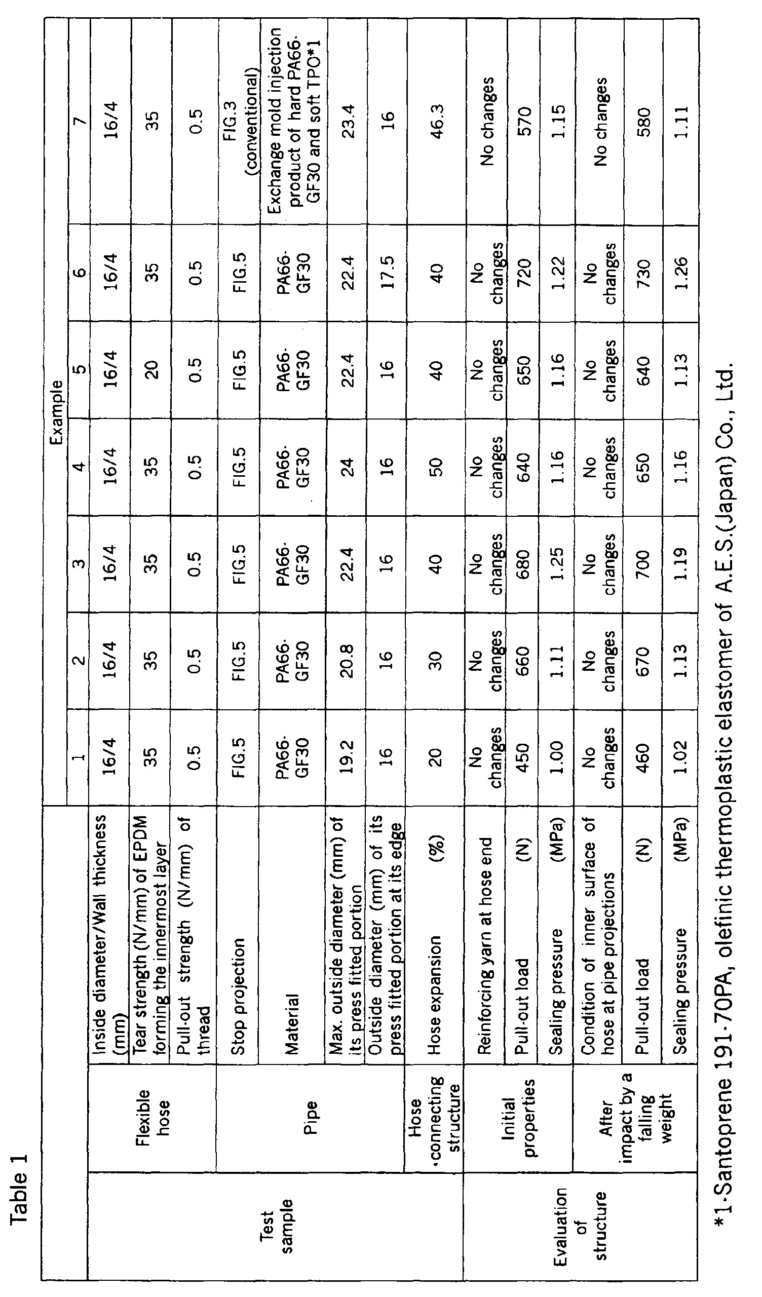
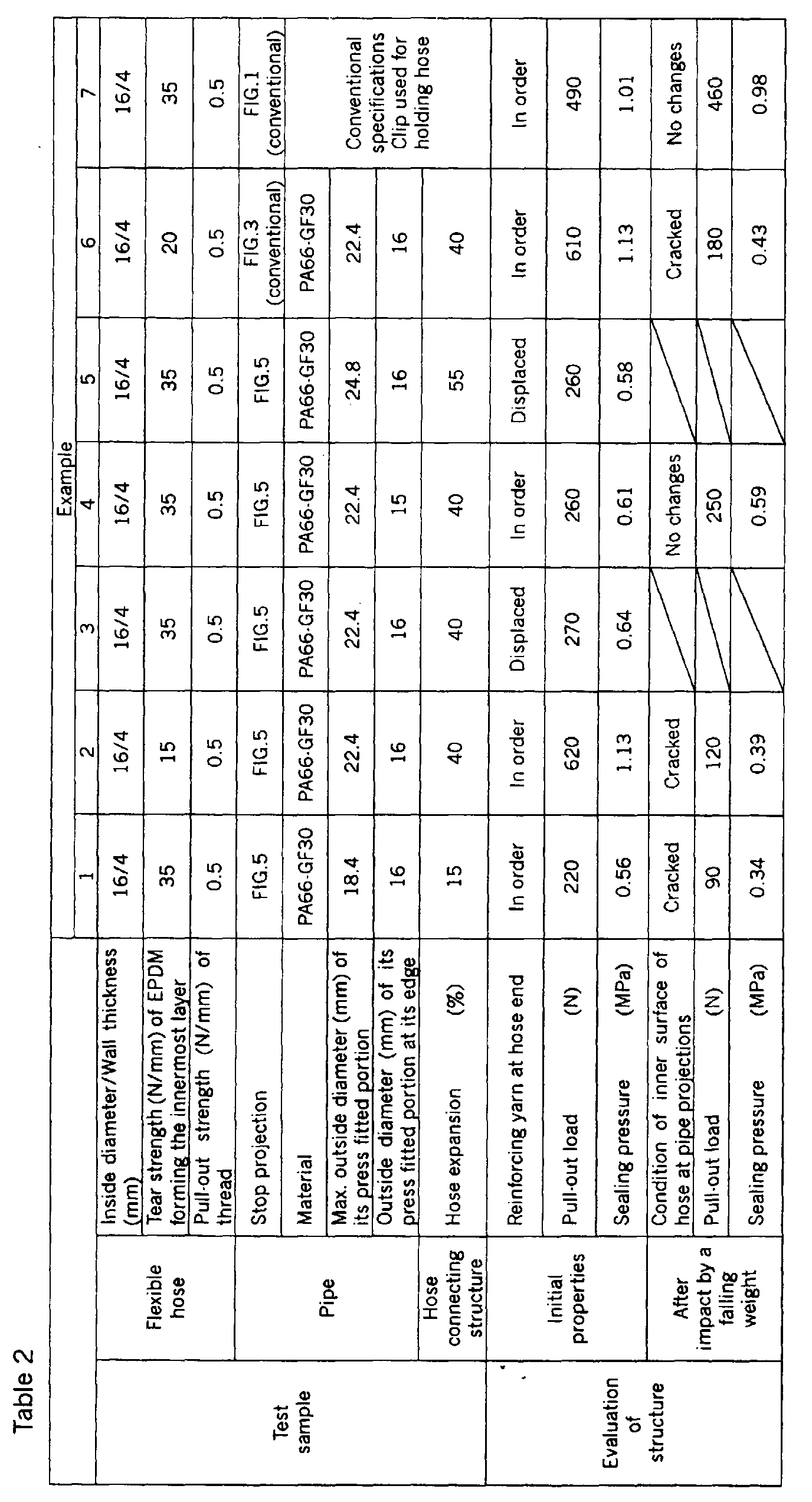
- Hose connecting structures according to this invention and conventional ones were prepared using a high, in some cases very high, percentage of expansion of the hoses, and are shown at Nos. 1 to 7 in Tables 1 and 2.
- examples having a stop projection of FIG. 5 are those of the present invention and examples having a stop projection of FIG. 3 or FIG. 1 are comparative ones.
- PA66-GF30 means a material obtained by mixing nylon 66 and glass fiber in a weight ratio of 70:30.
- a coating layer of TPO were formed on the pipe of PA66-GF30 by exchange mold injection.
- TPO is Santoprene 191-70PA, an olefinic thermoplastic elastomer of A.E.S. (Japan) Co., Ltd.
- Example 7 of Table 2 represents a known structure with a clip as shown in FIG. 1 and irrelevant specifications are omitted.
- Each structure was also evaluated for its properties after application of an impact by a falling weight.
- the structure was mounted horizontally so as to have its longitudinal axis lying in parallel to the floor, and an iron ball having a weight of 500 g was allowed to fall on the structure from a height of 1 m.
Landscapes
- Engineering & Computer Science (AREA)
- General Engineering & Computer Science (AREA)
- Mechanical Engineering (AREA)
- Rigid Pipes And Flexible Pipes (AREA)
- Joints That Cut Off Fluids, And Hose Joints (AREA)
Abstract
Description
Claims (10)
- A hose connecting structure comprising a flexible hose having a reinforcing fiber layer in its wall, and a hard pipe having a portion press fitted in said hose, wherein, said pipe has an annular stop projection formed about its press fitted portion, and having a cross sectional contour including a gentle outward slope extending from the front end of said projection toward the rear end side to a first corner, which makes the angle of the subsequent second corner gentle, and a rear face at said second corner extending inwardly toward the longitudinal axis of said pipe at right angles thereto.
- The structure as set forth in claim 1, wherein a top face of said projection from said first corner to said second corner is in parallel to, or inclined inwardly or outwardly from a line x parallel to the longitudinal axis of said pipe, and said second corner has an angle of 70° to 110°.
- The structure as set forth in claim 1 or 2, wherein said first and second corners have therebetween a distance of 0.5 to 5 mm as measured along a line x parallel to the longitudinal axis of said pipe.
- The structure as set forth in any one of claims 1 to 3, wherein said pipe is coated with a thin layer of a soft elastomer covering at least said press fitted portion, or said projection.
- The structure as set forth in claim 4, wherein said elastomer layer is formed by exchange mold injection when said pipe is molded.
- The structure as set forth in any one of claims 1 to 5, wherein said reinforcing fiber layer has a pull-out strength of thread of at least 0.3 N/mm.
- The structure as set forth in any one of claims 1 to 6, wherein at least an innermost wall layer of said hose is formed from an elastomer having a tear strength of at least 20 N/mm.
- The structure as set forth in any one of claims 1 to 7, wherein said hose has its inside diameter expanded by at least 20% by said press fitted portion of said pipe.
- The structure as set forth in any one of claims 1 to 8, wherein said hose has an initial inside diameter which is smaller than the outside diameter of said pipe at the forward edge of said press fitted portion thereof.
- The structure as set forth in any one of claims 1 to 9, wherein said hose is connected to a radiator, or heater in an automobile engine compartment.
Applications Claiming Priority (2)
| Application Number | Priority Date | Filing Date | Title |
|---|---|---|---|
| JP30400599 | 1999-10-26 | ||
| JP30400599A JP3870630B2 (en) | 1999-10-26 | 1999-10-26 | Hose joint structure |
Publications (2)
| Publication Number | Publication Date |
|---|---|
| EP1096195A1 true EP1096195A1 (en) | 2001-05-02 |
| EP1096195B1 EP1096195B1 (en) | 2006-05-31 |
Family
ID=17927923
Family Applications (1)
| Application Number | Title | Priority Date | Filing Date |
|---|---|---|---|
| EP00123010A Expired - Lifetime EP1096195B1 (en) | 1999-10-26 | 2000-10-23 | Hose connecting structure |
Country Status (4)
| Country | Link |
|---|---|
| US (1) | US6408890B1 (en) |
| EP (1) | EP1096195B1 (en) |
| JP (1) | JP3870630B2 (en) |
| DE (1) | DE60028320D1 (en) |
Families Citing this family (18)
| Publication number | Priority date | Publication date | Assignee | Title |
|---|---|---|---|---|
| JP2004332892A (en) * | 2003-05-12 | 2004-11-25 | Tokai Rubber Ind Ltd | Fiber reinforced hose |
| JP4309772B2 (en) * | 2004-01-15 | 2009-08-05 | アルプス電気株式会社 | Magnetic detection element |
| US20060162144A1 (en) * | 2005-01-25 | 2006-07-27 | Stieler David C | Method of coupling fuel system components |
| US20060163243A1 (en) * | 2005-01-25 | 2006-07-27 | Stieler David C | Method of coupling fuel system components |
| US7263975B2 (en) * | 2005-01-25 | 2007-09-04 | Dana Corporation | Plastic coated metal fuel rail |
| US20060249213A1 (en) * | 2005-04-21 | 2006-11-09 | Stieler David C | Plastic coated metal heater and water tube assembly |
| JP4751975B2 (en) * | 2005-06-08 | 2011-08-17 | 株式会社 正和 | HEAT EXCHANGE DEVICE, NIPPLE AND MANUFACTURING METHOD THEREOF |
| WO2007145779A2 (en) * | 2006-06-14 | 2007-12-21 | Freudenberg-Nok General Partnership | Tube seal components |
| FR2903756B1 (en) * | 2006-07-13 | 2008-12-12 | Plastic Omnium Cie | NOISE ATTENUATOR FOR HYDRAULIC FLUID DRIVE, ARTICLE COMPRISING THIS ATTENUATOR, CONDUCT COMPRISING THIS ARTICLE AND METHOD OF ASSEMBLY. |
| JP2008223935A (en) * | 2007-03-14 | 2008-09-25 | Bridgestone Corp | Hose fall out preventing fitting and hose fall out preventing structure using the same |
| US20090267307A1 (en) * | 2008-04-28 | 2009-10-29 | Freudenberg-Nok General Partnership | High Pressure Tube Seal |
| JP5614793B2 (en) * | 2008-12-12 | 2014-10-29 | 矢崎総業株式会社 | Structure for preventing incorrect assembly of packing |
| DE102013101988A1 (en) * | 2013-02-28 | 2014-08-28 | Maschinenfabrik Rieter Ag | Spinning station for producing a yarn |
| US20150130184A1 (en) * | 2013-11-12 | 2015-05-14 | Techafx, Inc. | Barbed hose end fitting apparatus for ptfe core hose |
| DE102015109158A1 (en) * | 2015-06-10 | 2016-12-15 | B. Braun Avitum Ag | Coupling for hose connections |
| US10788150B2 (en) | 2018-03-22 | 2020-09-29 | Freudenberg-Nok General Partnership | Tube seal |
| US12313194B1 (en) | 2021-09-24 | 2025-05-27 | Rockler Companies, Inc. | Mountable dust hose connector system |
| DE202023107420U1 (en) | 2023-12-15 | 2025-03-18 | Rehau Automotive Se & Co. Kg | System for securely connecting a hose to a connector |
Citations (6)
| Publication number | Priority date | Publication date | Assignee | Title |
|---|---|---|---|---|
| DE6942443U (en) * | 1969-10-31 | 1970-06-04 | Selbach Gmbh | COOLING PIPE. |
| US3653692A (en) * | 1970-02-09 | 1972-04-04 | John W Henson | Hose coupling method and means |
| US3711130A (en) * | 1970-11-09 | 1973-01-16 | Air Prod & Chem | Ferruleless barbed tubing connector |
| JPH08270857A (en) * | 1995-03-28 | 1996-10-15 | Tokai Rubber Ind Ltd | Hose connection fittings |
| DE19653257A1 (en) * | 1996-12-20 | 1998-06-25 | Mannesmann Vdo Ag | Hose coupling provided for connecting a hose with a second component |
| JPH10231977A (en) * | 1998-03-30 | 1998-09-02 | Tokai Rubber Ind Ltd | Hose connection structure |
Family Cites Families (13)
| Publication number | Priority date | Publication date | Assignee | Title |
|---|---|---|---|---|
| NL94577C (en) * | 1953-05-26 | 1900-01-01 | ||
| US3210100A (en) * | 1962-04-09 | 1965-10-05 | Parker Hannifin Corp | Hose coupling |
| US3252720A (en) * | 1963-03-27 | 1966-05-24 | Atlas Copco Ab | Swivel-type hose coupling |
| US3759445A (en) * | 1973-01-02 | 1973-09-18 | R King | Flexible fitting for lawn sprinkler systems |
| US3966238A (en) * | 1974-04-29 | 1976-06-29 | Parker-Hannifin Corporation | Hose construction and hose coupling joint |
| DE3887386T2 (en) * | 1987-06-01 | 1994-05-26 | Yokohama Rubber Co Ltd | Hose construction. |
| US5143122A (en) * | 1990-09-11 | 1992-09-01 | Bundy Corporation | Composite flexible conduit assembly |
| JPH04331894A (en) | 1991-05-08 | 1992-11-19 | Toyoda Gosei Co Ltd | Connection structure for hose |
| US5264262A (en) * | 1991-08-30 | 1993-11-23 | Tokai Rubber Industries, Inc. | Refrigerant transporting hose having inner tube including resin layer |
| US5358012A (en) * | 1993-03-18 | 1994-10-25 | Jem Industries, Inc. | Hose assembly having inner protective veneer and barbed nipple portion |
| US5413147A (en) * | 1993-04-29 | 1995-05-09 | Parker-Hannifin Corporation | Flexible hose and fitting assembly |
| JPH09159077A (en) | 1995-12-11 | 1997-06-17 | Toyoda Gosei Co Ltd | Hose connecting structure |
| US5685345A (en) * | 1995-12-21 | 1997-11-11 | Donaldson Company, Inc. | Reinforcing structure for conduit; and method |
-
1999
- 1999-10-26 JP JP30400599A patent/JP3870630B2/en not_active Expired - Fee Related
-
2000
- 2000-10-18 US US09/690,894 patent/US6408890B1/en not_active Expired - Lifetime
- 2000-10-23 DE DE60028320T patent/DE60028320D1/en not_active Expired - Lifetime
- 2000-10-23 EP EP00123010A patent/EP1096195B1/en not_active Expired - Lifetime
Patent Citations (6)
| Publication number | Priority date | Publication date | Assignee | Title |
|---|---|---|---|---|
| DE6942443U (en) * | 1969-10-31 | 1970-06-04 | Selbach Gmbh | COOLING PIPE. |
| US3653692A (en) * | 1970-02-09 | 1972-04-04 | John W Henson | Hose coupling method and means |
| US3711130A (en) * | 1970-11-09 | 1973-01-16 | Air Prod & Chem | Ferruleless barbed tubing connector |
| JPH08270857A (en) * | 1995-03-28 | 1996-10-15 | Tokai Rubber Ind Ltd | Hose connection fittings |
| DE19653257A1 (en) * | 1996-12-20 | 1998-06-25 | Mannesmann Vdo Ag | Hose coupling provided for connecting a hose with a second component |
| JPH10231977A (en) * | 1998-03-30 | 1998-09-02 | Tokai Rubber Ind Ltd | Hose connection structure |
Non-Patent Citations (2)
| Title |
|---|
| PATENT ABSTRACTS OF JAPAN vol. 1997, no. 02 28 February 1997 (1997-02-28) * |
| PATENT ABSTRACTS OF JAPAN vol. 1998, no. 14 31 December 1998 (1998-12-31) * |
Also Published As
| Publication number | Publication date |
|---|---|
| EP1096195B1 (en) | 2006-05-31 |
| DE60028320D1 (en) | 2006-07-06 |
| JP2001124275A (en) | 2001-05-11 |
| JP3870630B2 (en) | 2007-01-24 |
| US6408890B1 (en) | 2002-06-25 |
Similar Documents
| Publication | Publication Date | Title |
|---|---|---|
| US6408890B1 (en) | Hose connecting structure | |
| US7014214B2 (en) | Resinous connector | |
| JP2715870B2 (en) | Thermoplastic pipe fittings | |
| KR960006172B1 (en) | Hose | |
| US4235558A (en) | Ball joint design | |
| EP1055859B1 (en) | Tube clamping structure | |
| US20060138770A1 (en) | Connecting pipe | |
| EP2075495A1 (en) | Multilayer article | |
| JPH09264468A (en) | Hose connecting structure | |
| JP2006143172A (en) | Weld joints in fuel tanks | |
| JPS6229242Y2 (en) | ||
| JP6748002B2 (en) | Friction transmission belt and manufacturing method thereof | |
| US7503589B2 (en) | Connector assembly and method for connecting hoses | |
| CN206072608U (en) | A kind of transit joint | |
| JP2001221379A (en) | Hose for transporting carbon dioxide refrigerant | |
| JPH06249384A (en) | Pipe coupling made of synthetic resin for adhesion joining | |
| JPH0336792Y2 (en) | ||
| US20030099800A1 (en) | Multilayer hose for conveying motor vehicle fluids | |
| JPH09159077A (en) | Hose connecting structure | |
| US5303962A (en) | Crimped hose coupling for reinforced hoses | |
| US20090169791A1 (en) | Multilayer article | |
| EP1162396B1 (en) | Hose pipe | |
| JPH027053Y2 (en) | ||
| KR102598165B1 (en) | automotive washer fluid hose | |
| JPH04129832A (en) | Resin made fuel feeding pipe |
Legal Events
| Date | Code | Title | Description |
|---|---|---|---|
| PUAI | Public reference made under article 153(3) epc to a published international application that has entered the european phase |
Free format text: ORIGINAL CODE: 0009012 |
|
| 17P | Request for examination filed |
Effective date: 20001023 |
|
| AK | Designated contracting states |
Kind code of ref document: A1 Designated state(s): DE FR GB |
|
| AX | Request for extension of the european patent |
Free format text: AL;LT;LV;MK;RO;SI |
|
| AKX | Designation fees paid |
Free format text: DE FR GB |
|
| 17Q | First examination report despatched |
Effective date: 20020730 |
|
| GRAP | Despatch of communication of intention to grant a patent |
Free format text: ORIGINAL CODE: EPIDOSNIGR1 |
|
| GRAS | Grant fee paid |
Free format text: ORIGINAL CODE: EPIDOSNIGR3 |
|
| GRAA | (expected) grant |
Free format text: ORIGINAL CODE: 0009210 |
|
| AK | Designated contracting states |
Kind code of ref document: B1 Designated state(s): DE FR GB |
|
| REG | Reference to a national code |
Ref country code: GB Ref legal event code: FG4D |
|
| REF | Corresponds to: |
Ref document number: 60028320 Country of ref document: DE Date of ref document: 20060706 Kind code of ref document: P |
|
| PG25 | Lapsed in a contracting state [announced via postgrant information from national office to epo] |
Ref country code: DE Free format text: LAPSE BECAUSE OF FAILURE TO SUBMIT A TRANSLATION OF THE DESCRIPTION OR TO PAY THE FEE WITHIN THE PRESCRIBED TIME-LIMIT Effective date: 20060901 |
|
| ET | Fr: translation filed | ||
| PLBE | No opposition filed within time limit |
Free format text: ORIGINAL CODE: 0009261 |
|
| STAA | Information on the status of an ep patent application or granted ep patent |
Free format text: STATUS: NO OPPOSITION FILED WITHIN TIME LIMIT |
|
| 26N | No opposition filed |
Effective date: 20070301 |
|
| GBPC | Gb: european patent ceased through non-payment of renewal fee |
Effective date: 20061023 |
|
| PG25 | Lapsed in a contracting state [announced via postgrant information from national office to epo] |
Ref country code: GB Free format text: LAPSE BECAUSE OF NON-PAYMENT OF DUE FEES Effective date: 20061023 |
|
| REG | Reference to a national code |
Ref country code: FR Ref legal event code: CD Owner name: SUMITOMO RIKO COMPANY LIMITED, JP Effective date: 20141203 |
|
| REG | Reference to a national code |
Ref country code: FR Ref legal event code: PLFP Year of fee payment: 16 |
|
| REG | Reference to a national code |
Ref country code: FR Ref legal event code: PLFP Year of fee payment: 17 |
|
| REG | Reference to a national code |
Ref country code: FR Ref legal event code: PLFP Year of fee payment: 18 |
|
| REG | Reference to a national code |
Ref country code: FR Ref legal event code: PLFP Year of fee payment: 19 |
|
| PGFP | Annual fee paid to national office [announced via postgrant information from national office to epo] |
Ref country code: FR Payment date: 20180913 Year of fee payment: 19 |
|
| PG25 | Lapsed in a contracting state [announced via postgrant information from national office to epo] |
Ref country code: FR Free format text: LAPSE BECAUSE OF NON-PAYMENT OF DUE FEES Effective date: 20191031 |