EP1096174A1 - Blade tensioner with retaining pin and bracket - Google Patents
Blade tensioner with retaining pin and bracket Download PDFInfo
- Publication number
- EP1096174A1 EP1096174A1 EP00308484A EP00308484A EP1096174A1 EP 1096174 A1 EP1096174 A1 EP 1096174A1 EP 00308484 A EP00308484 A EP 00308484A EP 00308484 A EP00308484 A EP 00308484A EP 1096174 A1 EP1096174 A1 EP 1096174A1
- Authority
- EP
- European Patent Office
- Prior art keywords
- shoe
- blade
- bracket
- blade spring
- chain
- Prior art date
- Legal status (The legal status is an assumption and is not a legal conclusion. Google has not performed a legal analysis and makes no representation as to the accuracy of the status listed.)
- Granted
Links
Images

Classifications
-
- F—MECHANICAL ENGINEERING; LIGHTING; HEATING; WEAPONS; BLASTING
- F16—ENGINEERING ELEMENTS AND UNITS; GENERAL MEASURES FOR PRODUCING AND MAINTAINING EFFECTIVE FUNCTIONING OF MACHINES OR INSTALLATIONS; THERMAL INSULATION IN GENERAL
- F16H—GEARING
- F16H7/00—Gearings for conveying rotary motion by endless flexible members
- F16H7/08—Means for varying tension of belts, ropes or chains
-
- F—MECHANICAL ENGINEERING; LIGHTING; HEATING; WEAPONS; BLASTING
- F16—ENGINEERING ELEMENTS AND UNITS; GENERAL MEASURES FOR PRODUCING AND MAINTAINING EFFECTIVE FUNCTIONING OF MACHINES OR INSTALLATIONS; THERMAL INSULATION IN GENERAL
- F16H—GEARING
- F16H7/00—Gearings for conveying rotary motion by endless flexible members
- F16H7/08—Means for varying tension of belts, ropes or chains
- F16H2007/0802—Actuators for final output members
- F16H2007/0804—Leaf springs
-
- F—MECHANICAL ENGINEERING; LIGHTING; HEATING; WEAPONS; BLASTING
- F16—ENGINEERING ELEMENTS AND UNITS; GENERAL MEASURES FOR PRODUCING AND MAINTAINING EFFECTIVE FUNCTIONING OF MACHINES OR INSTALLATIONS; THERMAL INSULATION IN GENERAL
- F16H—GEARING
- F16H7/00—Gearings for conveying rotary motion by endless flexible members
- F16H7/08—Means for varying tension of belts, ropes or chains
- F16H2007/0863—Finally actuated members, e.g. constructional details thereof
- F16H2007/0872—Sliding members
-
- F—MECHANICAL ENGINEERING; LIGHTING; HEATING; WEAPONS; BLASTING
- F16—ENGINEERING ELEMENTS AND UNITS; GENERAL MEASURES FOR PRODUCING AND MAINTAINING EFFECTIVE FUNCTIONING OF MACHINES OR INSTALLATIONS; THERMAL INSULATION IN GENERAL
- F16H—GEARING
- F16H7/00—Gearings for conveying rotary motion by endless flexible members
- F16H7/08—Means for varying tension of belts, ropes or chains
- F16H2007/0876—Control or adjustment of actuators
- F16H2007/0878—Disabling during transport
-
- F—MECHANICAL ENGINEERING; LIGHTING; HEATING; WEAPONS; BLASTING
- F16—ENGINEERING ELEMENTS AND UNITS; GENERAL MEASURES FOR PRODUCING AND MAINTAINING EFFECTIVE FUNCTIONING OF MACHINES OR INSTALLATIONS; THERMAL INSULATION IN GENERAL
- F16H—GEARING
- F16H7/00—Gearings for conveying rotary motion by endless flexible members
- F16H7/18—Means for guiding or supporting belts, ropes, or chains
Definitions
- This invention relates to a tensioners used with chain drives in automotive timing applications and more particularly to a blade-type tensioner which is provided mounted to a bracket and held in place by a retaining pin for shipping and convenient assembly to an engine.
- Tensioning devices are used as a control device for a power transmission chain as the chain travels between a plurality of sprockets.
- it is important to impart and maintain a certain degree of tension to the chain to prevent noises or slippage.
- Prevention of slippage is especially important in the case of a chain driven camshaft in an internal combustion engine because slippage may alter the camshaft timing by several degrees, possibly causing damage.
- chain tension can vary between excessively high or low levels as a result of the wide variations in temperature and differences between the coefficients of linear expansion among the various parts of the engine, including the chain and the tensioner.
- Camshaft and crankshaft induced torsional vibration cause chain tension to vary considerably. This tension variation results in chain elongation.
- wear of the chain components during prolonged use can cause elongation of the chain that results in a decrease in the tension of the chain.
- blade-type tensioners use a spring blade interlocked wider tension with a plastic shoe to provide tension to a chain.
- the blade spring Before assembly into a operable tensioner the blade spring is preformed into an arcuate shape and the shoe is provided relatively flat.
- the shoe is constructed from a semi-rigid material which will deform or "creep" upon experiencing a load at high temperature.
- the blade spring is flattened to correspond to the shape of the shoe and then interlocked with it. Because the semi-rigid shoe prevents the blade spring from returning to its original more arcuate shape, the blade spring applies a load to the shoe.
- the heat from the engine causes the temperature of the shoe to increase and become less rigid.
- the load from the blade spring causes the shoe to deform to a more arcuate shape. Through such deformation, tension is provided to a chain.
- the chain tensioner is positioned to act against a free length of the chain between the sprocket gears. As the blade spring forces the shoe into a more arcuate shape, the apex of the shoe extends farther into the span of chain thereby increasing chain tension.
- Typical blade-type chain tensioners have interlocked a blade spring to a shoe.
- U.S. Pat. No. 3,490,302 to Turner et al., incorporated herein by reference, discloses a chain tensioner where the blade spring is mounted to mechanically interlock with, and thereby provide a load to, a shoe through a hole and pin combination. The blade spring continuously bears against the shoe.
- blade-type tensioners have a drawback.
- blade-type tensioners are used in confined spaces and are supplied to engine assembly plants in a straight form for ease of assembly in the engine.
- the tensioner is fixed to a bracket in the flattened form by a retaining pin which passes between the blade spring and the shoe and engages a notch or slot formed in the shoe itself and further passes through a hole in the bracket fixing the blade tensioner in place.
- the formation of the notch in the shoe requires an additional manufacturing step and forms a potential weak spot in the shoe.
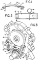
- the prior art blade spring tensioner 10 is shown in FIGS. 1-3.
- the shoe 30 has a blade spring interconnected thereto, the blade spring including a pair of blade spring members 20, 22 disposed along a bottom face 21 of the shoe 30.
- One end of the blade spring is held by being inserted into a slot in the shoe.
- the other end of the blade spring has an opening 80 which is fitted over a projection 60 on the corresponding end of the shoe and is locked in place by a solid or split pin 50 passing crosswise through the projection 60.
- a slot 70 is formed near the center of the bottom face 21 of the shoe 30 adapted to receive a retaining pin 55 (shown in FIG. 2).
- the tensioner 10 is first mounted to the bracket 15, the retaining pin 55 is passed through the tab 25 formed on the bracket 15 aligned with the slot 70 in the center portion of the shoe 30 and through a hole formed in the bracket, thus locking the shoe in place.
- FIG. 3 illustrates the prior art blade tensioner 10 as applied to a generalized power transmission system including a driving sprocket 81, a driven sprocket 82 and a chain 84 connecting the two sprockets.
- the blade tensioner 10 is mounted to the bracket 15 which, when mounted to the engine block 86, directs the upper face 23 of the tensioner shoe 30 to tension the slack portion of the chain 84.
- the bracket 15 includes a tab 25 spaced outward from the bracket face and located adjacent to the mid portion of the tensioner shoe 30.
- the bracket 15 further includes a passive snubber 88 generally opposite the tensioner 10 and applied to the drive side of the chain.
- the present invention is directed to a blade tensioner that addresses the problem of retaining the tensioner to the bracket by supplying a ready-to-use assembly that is easy and inexpensive to manufacture, simple to apply to an engine and results in a stronger tensioner.
- the present invention is directed to a chain tensioner comprising a blade spring in interlocked association with a plastic shoe.
- the shoe includes a mechanism to securely retain the blade spring thereagainst and a further releasable mechanism to retain the tensioner in a retracted position when mounted upon on a bracket until the unit is installed in an engine timing system and released to permit operation.
- the bottom face at one end of the tensioner shoe has a knurl with a transverse bore for pivotal attachment to a pivot pin.
- a pair of longitudinal spring slots are formed in the knurl.
- the other end of the shoe has a protrusion on the bottom face.
- a bore is formed through the protrusion transverse to the longitudinal axis of the shoe. The bores of the knurl and the protrusion are parallel to each other.
- One end of the blade spring is inserted into the spring slots and the other end of the blade spring has an opening which fits over the protrusion.
- the blade spring is interlocked onto the shoe by a hollow roll pin located in the bore of the protrusion.
- the interlocked shoe and blade spring are assembled to a bracket.
- the bracket includes a pivot pin extending from the face of the bracket for pivotal mounting of the first end of the shoe.
- the bracket also has a notched tab spaced outward from the bracket face and located adjacent the protrusion at the second or free end of the shoe.
- a retaining pin engages the notch in the tab and passes through the hollow roll pin thereby retaining the shoe to the bracket in a retracted state prior to application of the assembly to an engine.
- An integral passive snubber is attached to the bracket generally opposite the tensioner.
- FIGS. 4, 5 and 6 disclose a preferred embodiment of the chain tensioner apparatus of the present invention.
- the chain tensioner of the present invention may be used in various engine types and configurations (including that illustrated in FIG. 3) in conjunction with various types of chain including but not limited to timing chains, power transmission chains, and the like.
- the shoe 130 is preferably made of a plastic material that will creep under a continuous load applied thereto by the blade spring.
- the plastic material is preferably heat stabilized nylon 6/6.
- the shoe 130 also includes a mechanism to securely retain the blade spring means thereagainst, and in the preferred embodiment includes a hollow roll pin 150.
- the blade spring may be a single or a plurality of generally flat, rectangular steel blade spring members. Each end of the blade spring may have a rounded knuckle formed to bear upon the bottom face of the shoe to reduce gouging of the shoe.
- each spring member may be made of different materials, may have differing thicknesses, and may be subjected to any of a variety of different pretreatment processes, as known in the art, to match the characteristics of the blade spring to the desired load sought to be applied against the chain.
- the blade spring is inserted within the shoe 130 as follows. While FIG. 4 depicts multiple spring members 120,122 and FIGS. 5 and 6 depict a single blade spring 122, it should be understood that reference to a blade spring 122 contemplates either single or multiple spring members.
- the blade spring 122 or pair of blade spring members 120,122 are deformed to correspond to the shape of the bottom face 121 of the shoe.
- the plastic shoe 130 is preferably molded straight or with very little curvature to allow for ease of assembly in the engine. Therefore, the blade spring must be deflected from its natural curve to a straight position for mechanical assembly within the shoe.
- a first end of the blade spring which in one embodiment has a longitudinal slot 181 formed therein causing the spring to have two slat-like end portions, is inserted into slots formed in the knurl 165 at the first end 142 of the shoe 130.
- the second end of the blade spring 122 which has an opening 180 formed therein is fitted over a protrusion 160.
- the protrusion 160 extends from the bottom face 121 of the second end 140 of the shoe.
- a sleeve 150 which is hollow and preferably made of metal, is inserted through a bore in the protrusion 160. The bore is formed transverse to the longitudinal axis of the blade spring 122 and the shoe 130.
- the cylindrical sleeve 150 holds the blade spring 122 against the bottom face 121 of the shoe 130.
- the blade spring 122 is therefore mechanically interlocked with the plastic shoe 130.
- the term interlocked does not comprehend bonding by adhesives, molding, or connection by riveting, bolting or screwing.
- the pivot pin 190 is attached to one corner of the generally Y-shaped bracket 115.
- the interlocked blade spring 120,122 and shoe 130 is pivotally mounted to the pivot pin 190 by a transverse bore formed through the knurl 165.
- Part of the bracket 115, adjacent the free or second end 140 of the shoe 130 is formed into a tab 135.
- the tab 135 is spaced outward from the bracket face and has a notch 145 aligned with the hollow roll pin 150.
- the retaining pin 155 when placed in the hollow roll pin 150 engages the notch 145 in the tab 135 and thus holds the blade tensioner 100 in a retracted position. Removal of the retaining pin 155, after the assembly is attached to an engine, frees the second end 140 of the tensioner, allowing the tensioner to contact and act against the chain.
- a passive snubber 188 for contact with the chain is attached to the bracket 115 located generally opposite the blade tensioner 100.
Landscapes
- Engineering & Computer Science (AREA)
- General Engineering & Computer Science (AREA)
- Mechanical Engineering (AREA)
- Devices For Conveying Motion By Means Of Endless Flexible Members (AREA)
Abstract
Description
- This invention relates to a tensioners used with chain drives in automotive timing applications and more particularly to a blade-type tensioner which is provided mounted to a bracket and held in place by a retaining pin for shipping and convenient assembly to an engine.
- Tensioning devices are used as a control device for a power transmission chain as the chain travels between a plurality of sprockets. Generally, it is important to impart and maintain a certain degree of tension to the chain to prevent noises or slippage. Prevention of slippage is especially important in the case of a chain driven camshaft in an internal combustion engine because slippage may alter the camshaft timing by several degrees, possibly causing damage. In the harsh environment in which an internal combustion engine operates, chain tension can vary between excessively high or low levels as a result of the wide variations in temperature and differences between the coefficients of linear expansion among the various parts of the engine, including the chain and the tensioner. Camshaft and crankshaft induced torsional vibration cause chain tension to vary considerably. This tension variation results in chain elongation. Moreover, wear of the chain components during prolonged use can cause elongation of the chain that results in a decrease in the tension of the chain.
- Generally, blade-type tensioners use a spring blade interlocked wider tension with a plastic shoe to provide tension to a chain. Before assembly into a operable tensioner the blade spring is preformed into an arcuate shape and the shoe is provided relatively flat. The shoe is constructed from a semi-rigid material which will deform or "creep" upon experiencing a load at high temperature. During assembly, the blade spring is flattened to correspond to the shape of the shoe and then interlocked with it. Because the semi-rigid shoe prevents the blade spring from returning to its original more arcuate shape, the blade spring applies a load to the shoe. After application of the tensioner to an engine, the heat from the engine, during operation, causes the temperature of the shoe to increase and become less rigid. The load from the blade spring causes the shoe to deform to a more arcuate shape. Through such deformation, tension is provided to a chain.
- The chain tensioner is positioned to act against a free length of the chain between the sprocket gears. As the blade spring forces the shoe into a more arcuate shape, the apex of the shoe extends farther into the span of chain thereby increasing chain tension.
- Typical blade-type chain tensioners have interlocked a blade spring to a shoe. For example, U.S. Pat. No. 3,490,302, to Turner et al., incorporated herein by reference, discloses a chain tensioner where the blade spring is mounted to mechanically interlock with, and thereby provide a load to, a shoe through a hole and pin combination. The blade spring continuously bears against the shoe.
- Yet another structure for mounting a blade spring to a single shoe is disclosed in U.S. Pat. No. 5,055,088, to Cradduck et al., incorporated herein by reference. This reference discloses a blade-type tensioner which utilizes a plurality of blade springs interlocked with a plastic shoe through a passageway in the shoe and fastened using a split, or solid pin.
- Unfortunately, the prior art blade-type tensioners have a drawback. Typically, blade-type tensioners are used in confined spaces and are supplied to engine assembly plants in a straight form for ease of assembly in the engine. In the prior art, the tensioner is fixed to a bracket in the flattened form by a retaining pin which passes between the blade spring and the shoe and engages a notch or slot formed in the shoe itself and further passes through a hole in the bracket fixing the blade tensioner in place. The formation of the notch in the shoe requires an additional manufacturing step and forms a potential weak spot in the shoe.
- The prior art
blade spring tensioner 10 is shown in FIGS. 1-3. Theshoe 30 has a blade spring interconnected thereto, the blade spring including a pair ofblade spring members bottom face 21 of theshoe 30. One end of the blade spring is held by being inserted into a slot in the shoe. The other end of the blade spring has anopening 80 which is fitted over aprojection 60 on the corresponding end of the shoe and is locked in place by a solid or splitpin 50 passing crosswise through theprojection 60. - A
slot 70 is formed near the center of thebottom face 21 of theshoe 30 adapted to receive a retaining pin 55 (shown in FIG. 2). When thetensioner 10 is first mounted to thebracket 15, theretaining pin 55 is passed through thetab 25 formed on thebracket 15 aligned with theslot 70 in the center portion of theshoe 30 and through a hole formed in the bracket, thus locking the shoe in place. - FIG. 3 illustrates the prior
art blade tensioner 10 as applied to a generalized power transmission system including a drivingsprocket 81, a drivensprocket 82 and achain 84 connecting the two sprockets. Theblade tensioner 10 is mounted to thebracket 15 which, when mounted to theengine block 86, directs theupper face 23 of thetensioner shoe 30 to tension the slack portion of thechain 84. Thebracket 15 includes atab 25 spaced outward from the bracket face and located adjacent to the mid portion of thetensioner shoe 30. Thebracket 15 further includes apassive snubber 88 generally opposite thetensioner 10 and applied to the drive side of the chain. - The present invention is directed to a blade tensioner that addresses the problem of retaining the tensioner to the bracket by supplying a ready-to-use assembly that is easy and inexpensive to manufacture, simple to apply to an engine and results in a stronger tensioner.
- The present invention is directed to a chain tensioner comprising a blade spring in interlocked association with a plastic shoe. The shoe includes a mechanism to securely retain the blade spring thereagainst and a further releasable mechanism to retain the tensioner in a retracted position when mounted upon on a bracket until the unit is installed in an engine timing system and released to permit operation.
- In one embodiment, the bottom face at one end of the tensioner shoe has a knurl with a transverse bore for pivotal attachment to a pivot pin. A pair of longitudinal spring slots are formed in the knurl. The other end of the shoe has a protrusion on the bottom face. A bore is formed through the protrusion transverse to the longitudinal axis of the shoe. The bores of the knurl and the protrusion are parallel to each other. One end of the blade spring is inserted into the spring slots and the other end of the blade spring has an opening which fits over the protrusion. The blade spring is interlocked onto the shoe by a hollow roll pin located in the bore of the protrusion.
- The interlocked shoe and blade spring are assembled to a bracket. The bracket includes a pivot pin extending from the face of the bracket for pivotal mounting of the first end of the shoe. The bracket also has a notched tab spaced outward from the bracket face and located adjacent the protrusion at the second or free end of the shoe. A retaining pin engages the notch in the tab and passes through the hollow roll pin thereby retaining the shoe to the bracket in a retracted state prior to application of the assembly to an engine. An integral passive snubber is attached to the bracket generally opposite the tensioner.
- The advantages and features of the chain tensioner apparatus of the present invention will be better understood by reference to the embodiments which are hereafter presented and depicted by way of example in the following description taken in conjunction with the accompanying drawings in which like reference numbers are used to indicate like elements.
-
- FIG. 1 is a front view of the blade tensioner of the prior art showing the notch formed in the shoe.
- FIG. 2 is a bottom view of the tensioner shown in FIG. 1 with the notch represented by a dashed line.
- FIG. 3 is a perspective view depicting the prior art chain tensioner apparatus in a "cam-in-block" drive train for an engine.
- FIG. 4 is a front view of the interlocked blade spring and shoe of the present invention.
- FIG. 5 is a bottom view of the blade tensioner shown in FIG. 4.
- FIG. 6 is a perspective view of the preferred embodiment of the chain tensioner apparatus of the present invention mounted to a bracket and held in place by a retaining pin.
-
- Turning now to the drawings, FIGS. 4, 5 and 6 disclose a preferred embodiment of the chain tensioner apparatus of the present invention. The chain tensioner of the present invention may be used in various engine types and configurations (including that illustrated in FIG. 3) in conjunction with various types of chain including but not limited to timing chains, power transmission chains, and the like.
- The
shoe 130 is preferably made of a plastic material that will creep under a continuous load applied thereto by the blade spring. The plastic material is preferably heat stabilized nylon 6/6. Theshoe 130 also includes a mechanism to securely retain the blade spring means thereagainst, and in the preferred embodiment includes ahollow roll pin 150. - The blade spring may be a single or a plurality of generally flat, rectangular steel blade spring members. Each end of the blade spring may have a rounded knuckle formed to bear upon the bottom face of the shoe to reduce gouging of the shoe. In the case of a blade spring being a plurality of spring members, each spring member may be made of different materials, may have differing thicknesses, and may be subjected to any of a variety of different pretreatment processes, as known in the art, to match the characteristics of the blade spring to the desired load sought to be applied against the chain.
- The blade spring is inserted within the
shoe 130 as follows. While FIG. 4 depicts multiple spring members 120,122 and FIGS. 5 and 6 depict asingle blade spring 122, it should be understood that reference to ablade spring 122 contemplates either single or multiple spring members. Theblade spring 122 or pair of blade spring members 120,122 are deformed to correspond to the shape of thebottom face 121 of the shoe. Theplastic shoe 130 is preferably molded straight or with very little curvature to allow for ease of assembly in the engine. Therefore, the blade spring must be deflected from its natural curve to a straight position for mechanical assembly within the shoe. A first end of the blade spring, which in one embodiment has alongitudinal slot 181 formed therein causing the spring to have two slat-like end portions, is inserted into slots formed in theknurl 165 at thefirst end 142 of theshoe 130. The second end of theblade spring 122 which has anopening 180 formed therein is fitted over aprotrusion 160. Theprotrusion 160 extends from thebottom face 121 of thesecond end 140 of the shoe. Asleeve 150, which is hollow and preferably made of metal, is inserted through a bore in theprotrusion 160. The bore is formed transverse to the longitudinal axis of theblade spring 122 and theshoe 130. Thecylindrical sleeve 150 holds theblade spring 122 against thebottom face 121 of theshoe 130. Theblade spring 122 is therefore mechanically interlocked with theplastic shoe 130. As used herein, the term interlocked does not comprehend bonding by adhesives, molding, or connection by riveting, bolting or screwing. - The
pivot pin 190 is attached to one corner of the generally Y-shapedbracket 115. The interlocked blade spring 120,122 andshoe 130 is pivotally mounted to thepivot pin 190 by a transverse bore formed through theknurl 165. Part of thebracket 115, adjacent the free orsecond end 140 of theshoe 130 is formed into atab 135. Thetab 135 is spaced outward from the bracket face and has anotch 145 aligned with thehollow roll pin 150. The retainingpin 155 when placed in thehollow roll pin 150 engages thenotch 145 in thetab 135 and thus holds theblade tensioner 100 in a retracted position. Removal of the retainingpin 155, after the assembly is attached to an engine, frees thesecond end 140 of the tensioner, allowing the tensioner to contact and act against the chain. - A
passive snubber 188 for contact with the chain is attached to thebracket 115 located generally opposite theblade tensioner 100. - Those skilled in the art to which the invention pertains may make modifications and other embodiments employing the principles of this invention without departing from its spirit or essential characteristics, particularly upon considering the foregoing teachings. The described embodiments are to be considered in all respects only as illustrative and not restrictive and the scope of the invention, is therefore, indicated by the appended claims rather than by the foregoing description. Consequently, while the invention has been described with reference to particular embodiments, modifications of structure, sequence, materials and the like would be apparent to those skilled in the art, yet still fall within the scope of the invention.
Claims (5)
- A blade tensioner assembly for use with a chain comprising:a bracket having a sidewall and a tab portion spaced outwardly from and substantially parallel to said sidewall, said tab portion having a notch formed therein,a pivot pin attached to said bracket and projecting laterally from said sidewall,a blade spring having first and second ends,a shoe having first and second ends adapted to receive said first and said second ends of said blade spring, said shoe being made of a plastic material which will creep when subjected to continuous stress applied thereto by said blade portion during operation of said chain along said blade portion,said first end of said shoe having a first bore formed therein,said second end of said shoe having a second bore formed therein, said shoe being pivotally disposed on said pivot pin by said second bore in said second end of said shoe,a cylindrical sleeve having a hollow center being disposed in said first bore of said shoe, said cylindrical sleeve and said notch in said bracket being substantially aligned,a retaining pin having an end inserted through said hollow center of said cylindrical sleeve, said retaining pin having a portion engaging said notch in said tab to thereby retain said shoe in a fixed position.
- The blade tensioner assembly of claim 1 wherein said blade spring has a slot extending inwardly from said first end and a slot extending inwardly from said second end.
- The blade tensioner assembly of claim 1 wherein a snubber is attached to said bracket generally opposite said shoe, said snubber being positioned to act on a free length of said chain.
- The blade tensioner assembly of claim 1 wherein said first end of said blade spring has an opening formed therein and said second end of said blade spring has a longitudinal slot extending inwardly therefrom.
- The blade tensioner assembly of claim 4 wherein said first end of said shoe has a projecting portion, said projecting portion of said shoe extending outwardly from a bottom face of said shoe, said protrusion being inserted through said opening of said blade spring when said blade spring is disposed along said bottom face of said shoe, said blade spring being held along said shoe by said cylindrical sleeve being disposed in said first bore.
Applications Claiming Priority (2)
| Application Number | Priority Date | Filing Date | Title |
|---|---|---|---|
| US427853 | 1999-10-27 | ||
| US09/427,853 US6238311B1 (en) | 1999-10-27 | 1999-10-27 | Blade tensioner with retaining pin and bracket |
Publications (2)
| Publication Number | Publication Date |
|---|---|
| EP1096174A1 true EP1096174A1 (en) | 2001-05-02 |
| EP1096174B1 EP1096174B1 (en) | 2004-07-07 |
Family
ID=23696553
Family Applications (1)
| Application Number | Title | Priority Date | Filing Date |
|---|---|---|---|
| EP00308484A Expired - Lifetime EP1096174B1 (en) | 1999-10-27 | 2000-09-27 | Blade tensioner with retaining pin and bracket |
Country Status (4)
| Country | Link |
|---|---|
| US (1) | US6238311B1 (en) |
| EP (1) | EP1096174B1 (en) |
| JP (1) | JP2001173735A (en) |
| DE (1) | DE60011979T2 (en) |
Cited By (6)
| Publication number | Priority date | Publication date | Assignee | Title |
|---|---|---|---|---|
| EP1323949A3 (en) * | 2001-12-27 | 2003-12-03 | BorgWarner Morse TEC Japan K.K. | Hydraulic tensioner with stop mechanism |
| EP1715217A2 (en) | 2005-04-18 | 2006-10-25 | BorgWarner Inc. | Mechanical chain tensioner with ratcheting device |
| WO2008019205A1 (en) * | 2006-08-11 | 2008-02-14 | Borgwarner Inc | Assembly system and method for a tensioned chain drive system |
| US7455606B2 (en) | 2005-06-08 | 2008-11-25 | Borgwarner Inc. | Mechanical chain tensioner with a rotational ratcheting device |
| GB2454295A (en) * | 2007-10-29 | 2009-05-06 | Tsubakimoto Chain Co | Spring-loaded tensioner lever having a stopper pin |
| CN103052828A (en) * | 2011-05-20 | 2013-04-17 | 雅马哈发动机株式会社 | Tension-applying member, tension-applying-member assembly, engine, and saddle-type vehicle |
Families Citing this family (18)
| Publication number | Priority date | Publication date | Assignee | Title |
|---|---|---|---|---|
| JP2001355688A (en) * | 2000-06-13 | 2001-12-26 | Borg Warner Automotive Kk | Blade tensioner |
| US6447416B1 (en) * | 2000-09-14 | 2002-09-10 | General Motors Corporation | Cam drive system tensioner |
| US6758777B2 (en) * | 2000-11-17 | 2004-07-06 | Cloyes Gear And Products, Inc. | Snap-fit chain guide with locking connector arrangement |
| US6913552B2 (en) * | 2002-01-23 | 2005-07-05 | Cloyes Gear And Products, Inc. | Snap-fit chain guide with saw-tooth fixing feature |
| US7097579B2 (en) * | 2003-10-15 | 2006-08-29 | Borgwarner Inc. | Pivoting chain guide and tensioner assembly |
| US7063635B2 (en) * | 2003-10-23 | 2006-06-20 | Borgwarner Inc. | Compliant chain guide with blade spring |
| US20050130776A1 (en) | 2003-12-11 | 2005-06-16 | Borgwarner Inc. | Cassette for securing shipping and assembly of a camshaft drive and timing system |
| JP5813113B2 (en) * | 2010-08-09 | 2015-11-17 | クロイズ ギア アンド プロダクツインコーポレイテッド | Blade tensioner with spring retaining mechanism |
| JP5813115B2 (en) * | 2010-08-30 | 2015-11-17 | クロイズ ギア アンド プロダクツインコーポレイテッド | Blade tensioner and bracket for blade tensioners including pocket pivot mechanism |
| US9206886B2 (en) | 2012-12-09 | 2015-12-08 | Cloyes Gear And Products, Inc. | Chain tensioner |
| DE102015008877A1 (en) * | 2015-07-08 | 2016-08-04 | Iwis Motorsysteme Gmbh & Co. Kg | Modular sliding or tensioning rail |
| CN107407380A (en) * | 2015-03-09 | 2017-11-28 | 克劳伊斯传动装置产品有限公司 | Chain tensioner plastic vanes with improved structural rigidity on the spring end reactive surface of the vane |
| DE102015011318A1 (en) * | 2015-08-28 | 2017-03-02 | Iwis Motorsysteme Gmbh & Co. Kg | Chain drive with combination rail |
| DE102016221797B4 (en) * | 2016-11-08 | 2020-03-26 | Schaeffler Technologies AG & Co. KG | Jig |
| JP6906840B2 (en) * | 2017-04-07 | 2021-07-21 | 株式会社椿本チエイン | Chain guide mechanism |
| JP7177343B2 (en) * | 2018-10-16 | 2022-11-24 | 株式会社椿本チエイン | chain tensioner |
| JP7525791B2 (en) * | 2021-01-15 | 2024-07-31 | 株式会社椿本チエイン | Chain guide mechanism |
| US11815180B2 (en) * | 2021-08-24 | 2023-11-14 | Schaeffler Technologies AG & Co. KG | Tensioner with stamped pivot pin |
Citations (3)
| Publication number | Priority date | Publication date | Assignee | Title |
|---|---|---|---|---|
| US3490302A (en) * | 1967-05-31 | 1970-01-20 | Borg Warner | Chain tensioner |
| US5055088A (en) * | 1990-06-08 | 1991-10-08 | Borg-Warner Automotive, Inc. | Spring blade chain tensioner |
| US5425680A (en) * | 1994-07-19 | 1995-06-20 | Cloyes Gear & Products, Inc. | Snap-fit chain tensioner apparatus and method |
Family Cites Families (9)
| Publication number | Priority date | Publication date | Assignee | Title |
|---|---|---|---|---|
| US4798562A (en) * | 1986-01-22 | 1989-01-17 | Moxee Innovations Corporation | Tensioning device for flexible drive element |
| US4921472A (en) | 1989-06-12 | 1990-05-01 | Borg-Warner Automotive Transmission & Engine Components Corporation | Chain tensioner |
| US5286234A (en) | 1992-07-27 | 1994-02-15 | Cloyes-Iwis Company L.P. | Chain tensioner apparatus |
| US5266066A (en) | 1992-08-21 | 1993-11-30 | Borg-Warner Automative, Inc. | Spring blade chain tensioner |
| US5462493A (en) | 1994-11-02 | 1995-10-31 | Borg-Warner Automotive, Inc. | Dual blade chain tensioner with damping |
| DE29603718U1 (en) | 1996-02-29 | 1997-06-26 | Joh. Winklhofer & Söhne GmbH und Co KG, 81369 München | Mechanical chain tensioner |
| US5711732A (en) * | 1996-03-06 | 1998-01-27 | Cloyes Gear And Products, Inc. | Chain tensioner apparatus and method |
| IT1290499B1 (en) * | 1997-03-28 | 1998-12-04 | Borg Warner Automotive | TENSIONER FOR CHAINS, WITH PLASTIC SHOE AND LAMINA SPRING (S) WITH CURVED ENDS |
| US6155941A (en) * | 1998-12-15 | 2000-12-05 | Borgwarner Inc. | Hydraulic tensioner having a flexible blade arm |
-
1999
- 1999-10-27 US US09/427,853 patent/US6238311B1/en not_active Expired - Fee Related
-
2000
- 2000-09-27 DE DE60011979T patent/DE60011979T2/en not_active Expired - Fee Related
- 2000-09-27 EP EP00308484A patent/EP1096174B1/en not_active Expired - Lifetime
- 2000-10-27 JP JP2000329136A patent/JP2001173735A/en not_active Abandoned
Patent Citations (3)
| Publication number | Priority date | Publication date | Assignee | Title |
|---|---|---|---|---|
| US3490302A (en) * | 1967-05-31 | 1970-01-20 | Borg Warner | Chain tensioner |
| US5055088A (en) * | 1990-06-08 | 1991-10-08 | Borg-Warner Automotive, Inc. | Spring blade chain tensioner |
| US5425680A (en) * | 1994-07-19 | 1995-06-20 | Cloyes Gear & Products, Inc. | Snap-fit chain tensioner apparatus and method |
Cited By (14)
| Publication number | Priority date | Publication date | Assignee | Title |
|---|---|---|---|---|
| EP1323949A3 (en) * | 2001-12-27 | 2003-12-03 | BorgWarner Morse TEC Japan K.K. | Hydraulic tensioner with stop mechanism |
| EP1715217A2 (en) | 2005-04-18 | 2006-10-25 | BorgWarner Inc. | Mechanical chain tensioner with ratcheting device |
| EP1715217A3 (en) * | 2005-04-18 | 2008-02-06 | BorgWarner Inc. | Mechanical chain tensioner with ratcheting device |
| US7513843B2 (en) | 2005-04-18 | 2009-04-07 | Borgwarner Inc. | Mechanical chain tensioner with ratcheting device |
| US7455606B2 (en) | 2005-06-08 | 2008-11-25 | Borgwarner Inc. | Mechanical chain tensioner with a rotational ratcheting device |
| US8387244B2 (en) | 2006-08-11 | 2013-03-05 | Borgwarner Inc. | Assembly system and method for a tensioned chain drive system |
| WO2008019205A1 (en) * | 2006-08-11 | 2008-02-14 | Borgwarner Inc | Assembly system and method for a tensioned chain drive system |
| CN101495775B (en) * | 2006-08-11 | 2011-09-07 | 博格华纳公司 | Assembly system and method for a tensioned chain drive system |
| GB2454295A (en) * | 2007-10-29 | 2009-05-06 | Tsubakimoto Chain Co | Spring-loaded tensioner lever having a stopper pin |
| GB2454295B (en) * | 2007-10-29 | 2012-05-09 | Tsubakimoto Chain Co | Tensioner lever for chain drive |
| US8092327B2 (en) | 2007-10-29 | 2012-01-10 | Tsubakimoto Chain Co. | Tensioner lever for chain drive |
| CN103052828A (en) * | 2011-05-20 | 2013-04-17 | 雅马哈发动机株式会社 | Tension-applying member, tension-applying-member assembly, engine, and saddle-type vehicle |
| EP2589835A4 (en) * | 2011-05-20 | 2014-03-12 | Yamaha Motor Co Ltd | VOLTAGE FORCE ELEMENT AND ASSOCIATED MOUNTING BODY, MOTOR, AND SLED VEHICLE |
| CN103052828B (en) * | 2011-05-20 | 2016-09-21 | 雅马哈发动机株式会社 | Electromotor, riding vehicle and installation method |
Also Published As
| Publication number | Publication date |
|---|---|
| DE60011979D1 (en) | 2004-08-12 |
| JP2001173735A (en) | 2001-06-26 |
| US6238311B1 (en) | 2001-05-29 |
| DE60011979T2 (en) | 2004-12-09 |
| EP1096174B1 (en) | 2004-07-07 |
Similar Documents
| Publication | Publication Date | Title |
|---|---|---|
| US6238311B1 (en) | Blade tensioner with retaining pin and bracket | |
| JP3516703B2 (en) | Chain tensioner | |
| EP0581219B1 (en) | Chain tensioner apparatus | |
| US5184983A (en) | Floating preventive structure for shoe of tensioner lever | |
| EP2016307B1 (en) | Chain tensioning device linking two strands of a chain drive | |
| CA2009929C (en) | Chain tensioner | |
| US6572502B1 (en) | Chain tensioner device for use in a confined space | |
| US5797818A (en) | Chain tensioner with damping feature | |
| US6093123A (en) | Integrated chain drive tensioner and sprocket assembly | |
| US5711732A (en) | Chain tensioner apparatus and method | |
| US5653652A (en) | Hydraulic tensioning system with dual arm blade | |
| US6447414B1 (en) | Hydraulic tensioner having flexible blade arm | |
| EP1915550B1 (en) | Pivoting mechanical tensioner with cross strand damping | |
| ITMI970738A1 (en) | TENSIONER FOR CHAINS WITH PLASTIC SHOE AND LAMINA SPRING (S) WITH CURVED ENDS | |
| JP2001271895A (en) | Chain guide and chain guide system | |
| EP1915549B1 (en) | Long mechanical tensioner with a compliant blade spring | |
| JPH09184550A (en) | Coil spring chain tensioner | |
| US6641496B2 (en) | Blade tensioner | |
| US6616557B2 (en) | Clip for blade tensioner and blade tensioner with clip | |
| US6354972B1 (en) | Chain tensioner assembly having a single-fastener mounting arrangement | |
| US6939260B2 (en) | Silent drive chain assembly having flexible links | |
| US7452295B2 (en) | Chains for power transmission | |
| US20050090346A1 (en) | Compliant chain guide with multiple joints | |
| EP1323949B1 (en) | Hydraulic tensioner with stop mechanism |
Legal Events
| Date | Code | Title | Description |
|---|---|---|---|
| PUAI | Public reference made under article 153(3) epc to a published international application that has entered the european phase |
Free format text: ORIGINAL CODE: 0009012 |
|
| AK | Designated contracting states |
Kind code of ref document: A1 Designated state(s): DE ES FR GB IT SE |
|
| AX | Request for extension of the european patent |
Free format text: AL;LT;LV;MK;RO;SI |
|
| 17P | Request for examination filed |
Effective date: 20011001 |
|
| AKX | Designation fees paid |
Free format text: DE ES FR GB IT SE |
|
| 17Q | First examination report despatched |
Effective date: 20030109 |
|
| GRAP | Despatch of communication of intention to grant a patent |
Free format text: ORIGINAL CODE: EPIDOSNIGR1 |
|
| GRAS | Grant fee paid |
Free format text: ORIGINAL CODE: EPIDOSNIGR3 |
|
| GRAA | (expected) grant |
Free format text: ORIGINAL CODE: 0009210 |
|
| RAP1 | Party data changed (applicant data changed or rights of an application transferred) |
Owner name: BORGWARNER INC. |
|
| AK | Designated contracting states |
Kind code of ref document: B1 Designated state(s): DE ES FR GB IT SE |
|
| PG25 | Lapsed in a contracting state [announced via postgrant information from national office to epo] |
Ref country code: ES Free format text: LAPSE BECAUSE OF FAILURE TO SUBMIT A TRANSLATION OF THE DESCRIPTION OR TO PAY THE FEE WITHIN THE PRESCRIBED TIME-LIMIT Effective date: 20040707 |
|
| REG | Reference to a national code |
Ref country code: GB Ref legal event code: FG4D |
|
| REF | Corresponds to: |
Ref document number: 60011979 Country of ref document: DE Date of ref document: 20040812 Kind code of ref document: P |
|
| PG25 | Lapsed in a contracting state [announced via postgrant information from national office to epo] |
Ref country code: GB Free format text: LAPSE BECAUSE OF NON-PAYMENT OF DUE FEES Effective date: 20041007 Ref country code: SE Free format text: LAPSE BECAUSE OF FAILURE TO SUBMIT A TRANSLATION OF THE DESCRIPTION OR TO PAY THE FEE WITHIN THE PRESCRIBED TIME-LIMIT Effective date: 20041007 |
|
| ET | Fr: translation filed | ||
| PLBE | No opposition filed within time limit |
Free format text: ORIGINAL CODE: 0009261 |
|
| STAA | Information on the status of an ep patent application or granted ep patent |
Free format text: STATUS: NO OPPOSITION FILED WITHIN TIME LIMIT |
|
| GBPC | Gb: european patent ceased through non-payment of renewal fee |
Effective date: 20041007 |
|
| 26N | No opposition filed |
Effective date: 20050408 |
|
| PGFP | Annual fee paid to national office [announced via postgrant information from national office to epo] |
Ref country code: FR Payment date: 20080904 Year of fee payment: 9 Ref country code: IT Payment date: 20080915 Year of fee payment: 9 |
|
| PGFP | Annual fee paid to national office [announced via postgrant information from national office to epo] |
Ref country code: DE Payment date: 20080930 Year of fee payment: 9 |
|
| REG | Reference to a national code |
Ref country code: FR Ref legal event code: ST Effective date: 20100531 |
|
| PG25 | Lapsed in a contracting state [announced via postgrant information from national office to epo] |
Ref country code: DE Free format text: LAPSE BECAUSE OF NON-PAYMENT OF DUE FEES Effective date: 20100401 Ref country code: FR Free format text: LAPSE BECAUSE OF NON-PAYMENT OF DUE FEES Effective date: 20090930 |
|
| PG25 | Lapsed in a contracting state [announced via postgrant information from national office to epo] |
Ref country code: IT Free format text: LAPSE BECAUSE OF NON-PAYMENT OF DUE FEES Effective date: 20090927 |