EP1096138A2 - Engine fuel supply system - Google Patents
Engine fuel supply system Download PDFInfo
- Publication number
- EP1096138A2 EP1096138A2 EP00123581A EP00123581A EP1096138A2 EP 1096138 A2 EP1096138 A2 EP 1096138A2 EP 00123581 A EP00123581 A EP 00123581A EP 00123581 A EP00123581 A EP 00123581A EP 1096138 A2 EP1096138 A2 EP 1096138A2
- Authority
- EP
- European Patent Office
- Prior art keywords
- fuel
- intake path
- injection valve
- intake
- supply system
- Prior art date
- Legal status (The legal status is an assumption and is not a legal conclusion. Google has not performed a legal analysis and makes no representation as to the accuracy of the status listed.)
- Granted
Links
- 239000000446 fuel Substances 0.000 title claims abstract description 283
- 238000002347 injection Methods 0.000 claims abstract description 75
- 239000007924 injection Substances 0.000 claims abstract description 75
- 230000006698 induction Effects 0.000 claims abstract description 51
- 238000011144 upstream manufacturing Methods 0.000 claims abstract description 17
- 238000000889 atomisation Methods 0.000 abstract description 12
- 238000002485 combustion reaction Methods 0.000 description 4
- 238000010276 construction Methods 0.000 description 2
- 239000000203 mixture Substances 0.000 description 2
- 238000009423 ventilation Methods 0.000 description 2
- 230000000903 blocking effect Effects 0.000 description 1
- 230000015556 catabolic process Effects 0.000 description 1
- 238000006731 degradation reaction Methods 0.000 description 1
- 230000002349 favourable effect Effects 0.000 description 1
- 239000002828 fuel tank Substances 0.000 description 1
- 230000001737 promoting effect Effects 0.000 description 1
- 238000007789 sealing Methods 0.000 description 1
- 238000004904 shortening Methods 0.000 description 1
- 239000007921 spray Substances 0.000 description 1
- 239000013589 supplement Substances 0.000 description 1
Images



Classifications
-
- F—MECHANICAL ENGINEERING; LIGHTING; HEATING; WEAPONS; BLASTING
- F02—COMBUSTION ENGINES; HOT-GAS OR COMBUSTION-PRODUCT ENGINE PLANTS
- F02M—SUPPLYING COMBUSTION ENGINES IN GENERAL WITH COMBUSTIBLE MIXTURES OR CONSTITUENTS THEREOF
- F02M35/00—Combustion-air cleaners, air intakes, intake silencers, or induction systems specially adapted for, or arranged on, internal-combustion engines
- F02M35/10—Air intakes; Induction systems
- F02M35/10209—Fluid connections to the air intake system; their arrangement of pipes, valves or the like
- F02M35/10216—Fuel injectors; Fuel pipes or rails; Fuel pumps or pressure regulators
-
- F—MECHANICAL ENGINEERING; LIGHTING; HEATING; WEAPONS; BLASTING
- F02—COMBUSTION ENGINES; HOT-GAS OR COMBUSTION-PRODUCT ENGINE PLANTS
- F02M—SUPPLYING COMBUSTION ENGINES IN GENERAL WITH COMBUSTIBLE MIXTURES OR CONSTITUENTS THEREOF
- F02M35/00—Combustion-air cleaners, air intakes, intake silencers, or induction systems specially adapted for, or arranged on, internal-combustion engines
- F02M35/10—Air intakes; Induction systems
- F02M35/10006—Air intakes; Induction systems characterised by the position of elements of the air intake system in direction of the air intake flow, i.e. between ambient air inlet and supply to the combustion chamber
- F02M35/10078—Connections of intake systems to the engine
- F02M35/10085—Connections of intake systems to the engine having a connecting piece, e.g. a flange, between the engine and the air intake being foreseen with a throttle valve, fuel injector, mixture ducts or the like
-
- F—MECHANICAL ENGINEERING; LIGHTING; HEATING; WEAPONS; BLASTING
- F02—COMBUSTION ENGINES; HOT-GAS OR COMBUSTION-PRODUCT ENGINE PLANTS
- F02M—SUPPLYING COMBUSTION ENGINES IN GENERAL WITH COMBUSTIBLE MIXTURES OR CONSTITUENTS THEREOF
- F02M35/00—Combustion-air cleaners, air intakes, intake silencers, or induction systems specially adapted for, or arranged on, internal-combustion engines
- F02M35/10—Air intakes; Induction systems
- F02M35/10091—Air intakes; Induction systems characterised by details of intake ducts: shapes; connections; arrangements
- F02M35/10118—Air intakes; Induction systems characterised by details of intake ducts: shapes; connections; arrangements with variable cross-sections of intake ducts along their length; Venturis; Diffusers
-
- F—MECHANICAL ENGINEERING; LIGHTING; HEATING; WEAPONS; BLASTING
- F02—COMBUSTION ENGINES; HOT-GAS OR COMBUSTION-PRODUCT ENGINE PLANTS
- F02M—SUPPLYING COMBUSTION ENGINES IN GENERAL WITH COMBUSTIBLE MIXTURES OR CONSTITUENTS THEREOF
- F02M69/00—Low-pressure fuel-injection apparatus ; Apparatus with both continuous and intermittent injection; Apparatus injecting different types of fuel
- F02M69/04—Injectors peculiar thereto
- F02M69/042—Positioning of injectors with respect to engine, e.g. in the air intake conduit
-
- F—MECHANICAL ENGINEERING; LIGHTING; HEATING; WEAPONS; BLASTING
- F02—COMBUSTION ENGINES; HOT-GAS OR COMBUSTION-PRODUCT ENGINE PLANTS
- F02M—SUPPLYING COMBUSTION ENGINES IN GENERAL WITH COMBUSTIBLE MIXTURES OR CONSTITUENTS THEREOF
- F02M69/00—Low-pressure fuel-injection apparatus ; Apparatus with both continuous and intermittent injection; Apparatus injecting different types of fuel
- F02M69/04—Injectors peculiar thereto
- F02M69/042—Positioning of injectors with respect to engine, e.g. in the air intake conduit
- F02M69/043—Positioning of injectors with respect to engine, e.g. in the air intake conduit for injecting into the intake conduit upstream of an air throttle valve
-
- F—MECHANICAL ENGINEERING; LIGHTING; HEATING; WEAPONS; BLASTING
- F02—COMBUSTION ENGINES; HOT-GAS OR COMBUSTION-PRODUCT ENGINE PLANTS
- F02M—SUPPLYING COMBUSTION ENGINES IN GENERAL WITH COMBUSTIBLE MIXTURES OR CONSTITUENTS THEREOF
- F02M69/00—Low-pressure fuel-injection apparatus ; Apparatus with both continuous and intermittent injection; Apparatus injecting different types of fuel
- F02M69/04—Injectors peculiar thereto
- F02M69/042—Positioning of injectors with respect to engine, e.g. in the air intake conduit
- F02M69/044—Positioning of injectors with respect to engine, e.g. in the air intake conduit for injecting into the intake conduit downstream of an air throttle valve
-
- F—MECHANICAL ENGINEERING; LIGHTING; HEATING; WEAPONS; BLASTING
- F02—COMBUSTION ENGINES; HOT-GAS OR COMBUSTION-PRODUCT ENGINE PLANTS
- F02M—SUPPLYING COMBUSTION ENGINES IN GENERAL WITH COMBUSTIBLE MIXTURES OR CONSTITUENTS THEREOF
- F02M69/00—Low-pressure fuel-injection apparatus ; Apparatus with both continuous and intermittent injection; Apparatus injecting different types of fuel
- F02M69/04—Injectors peculiar thereto
- F02M69/047—Injectors peculiar thereto injectors with air chambers, e.g. communicating with atmosphere for aerating the nozzles
-
- F—MECHANICAL ENGINEERING; LIGHTING; HEATING; WEAPONS; BLASTING
- F02—COMBUSTION ENGINES; HOT-GAS OR COMBUSTION-PRODUCT ENGINE PLANTS
- F02M—SUPPLYING COMBUSTION ENGINES IN GENERAL WITH COMBUSTIBLE MIXTURES OR CONSTITUENTS THEREOF
- F02M69/00—Low-pressure fuel-injection apparatus ; Apparatus with both continuous and intermittent injection; Apparatus injecting different types of fuel
- F02M69/30—Low-pressure fuel-injection apparatus ; Apparatus with both continuous and intermittent injection; Apparatus injecting different types of fuel characterised by means for facilitating the starting-up or idling of engines or by means for enriching fuel charge, e.g. below operational temperatures or upon high power demand of engines
- F02M69/32—Low-pressure fuel-injection apparatus ; Apparatus with both continuous and intermittent injection; Apparatus injecting different types of fuel characterised by means for facilitating the starting-up or idling of engines or by means for enriching fuel charge, e.g. below operational temperatures or upon high power demand of engines with an air by-pass around the air throttle valve or with an auxiliary air passage, e.g. with a variably controlled valve therein
- F02M69/325—Low-pressure fuel-injection apparatus ; Apparatus with both continuous and intermittent injection; Apparatus injecting different types of fuel characterised by means for facilitating the starting-up or idling of engines or by means for enriching fuel charge, e.g. below operational temperatures or upon high power demand of engines with an air by-pass around the air throttle valve or with an auxiliary air passage, e.g. with a variably controlled valve therein with an auxiliary injection nozzle therein
Definitions
- the present invention relates to an engine fuel supply system, with a fuel injection valve fitted in an intake path organizer forming an intake path communicating with an air cleaner, having a fuel passage for guiding fuel from the fuel injection valve, a fuel induction port having one end communicating with the fuel passage and the other end communicating with the intake path, and an air bleed passageway having one end communicating with the intake path further upstream than the fuel induction port and the other end communicating with the fuel passageway, all provided in the intake path organizer.
- a fuel supply system of the related art is already known, for example, from Japanese Patent Laid-open No. Hei. 5-26132.
- the present invention has been conceived in view of the above described problems, and the object of the present invention is to provide an engine fuel injection system that can promote fuel atomization much more.
- the invention as disclosed in claim 1 provides an engine fuel supply system, with a fuel injection valve fitted in an intake path organizer forming an intake path communicating with an air cleaner, having a fuel passage for guiding fuel from the fuel injection valve, a fuel induction port having one end communicating with the fuel passage and the other end communicating with the intake path, and an air bleed passageway having one end communicating with the intake path further upstream than the fuel induction port and the other end communicating with the fuel passageway, all provided in the intake path organizer, wherein the other end of the fuel induction port is opened to the intake path in a direction orthogonal to an air flow circulating in the intake path.
- the air flow and fuel sucked to the air flow side from the fuel induction port collide with each other because the fuel induction port opens in a direction orthogonal to air flow of the intake path, to effectively atomize the fuel, and by promoting atomization of the fuel it becomes possible to reduce fuel consumption and it also becomes possible to improve exhaust quality and engine output.
- the invention as disclosed in claim 2 is substantially the invention of claim 1, wherein the fuel induction port is provided in the intake path organizer opening to an inner surface of the intake path, and with this construction, it is possible to avoid increasing air-flow resistance without providing a structure that interferes with flow inside the intake path according to the arrangement of the fuel induction port.
- the invention disclosed in claim 3 is basically the invention of claim 2, wherein the other ends of a plurality of fuel induction ports open to an inner surface of the intake path at mutually opposite positions, and with this construction it becomes possible to prevent fuel sticking to the inner surface of the intake path and to much more effectively atomize the fuel, by causing collision of fuel sucked in to the air flow side from the mutually opposite fuel induction ports, and it is possible to significantly reduce fuel consumption as well as significantly improve exhaust quality and engine output.
- the invention disclosed in claim 4 is an engine fuel supply system, with a fuel injection valve fitted in an intake path organizer forming an intake path communicating with an air cleaner, having a fuel passage for guiding fuel from the fuel injection valve, a fuel induction port having one end communicating with the fuel passage and the other end communicating with the intake path, and an air bleed passageway having one end communicating with the intake path further upstream than the fuel induction port and the other end communicating with the fuel passageway, all provided in the intake path organizer, wherein a narrowed section constituting part of the intake path is provided in the intake path organizer with a smaller internal diameter than the intake path at an upstream side of the narrowed section, and the other end of the fuel induction port opens to an inner surface of the narrowed section in a direction orthogonal to an air flow circulating in the narrowed section.
- the air flow of the intake path and fuel sucked to the air flow side from the fuel induction port collide with each other making it possible to effectively atomize the fuel, it becomes possible to reduce fuel consumption and it also becomes possible to improve exhaust quality and engine output.
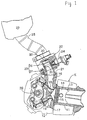
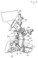
- FIG. 1 is a cut-away cross section showing an engine intake system
- Fig. 2 is an enlarged vertical cross section of an intake path organizer
- Fig. 3 is a cross section along line 3 - 3 in Fig. 2
- Fig. 4 is a drawing showing a relationship between fuel supply pressure and exhaust quality
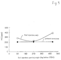
- Fig. 5 is a drawing showing a relationship between fuel injection timing and exhaust quality
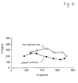
- Fig. 6 is a drawing showing a relationship between brake-mean effective pressure and exhaust quality.
- an engine E comprises a cylinder block 11 and a cylinder head 12 joined to the cylinder block 11, and a combustion chamber 15 is formed between a piston 14 slidably fitted in a cylinder bore 13 provided in the cylinder block 11, and the cylinder head 12.
- An intake port 16 and an exhaust port 17 capable of communicating with the combustion chamber are provided in the cylinder head 12, an intake valve 18 for switching between communication and disconnection between the intake port 16 and the combustion chamber, and an exhaust valve 17 for switching between communication and disconnection between the exhaust port and the combustion chamber, are supported in the cylinder head 12 so as to enable opening and closing operations, and the intake valve 18 and the exhaust valve 19 are driven to open and close by a conventional valve mechanism 20.
- a fuel supply system 22 is connected to the intake port 16 via an intake pipe 21.
- This fuel supply system 22 comprises an intake path organizer 23 and a fuel injection valve 24 mounted in the intake path organizer.
- the intake path organizer 23 is comprised of an intake path main component 26 having a passageway 25, and a narrowed section 27 fixed to the intake path main component 26 by fitting into a downstream side of the passageway 25.
- the intake path main component 23 includes an intake path 30 which has an upper end communicating with an air cleaner 29 via an intake hose 28, and a lower end communicating with the intake pipe 21.
- the intake path 30 is comprised of a section for removing sections to which the narrowing member 27 in the passageway 25 is fitted, and a narrowed section 31 formed at an inner surface of the narrowing member 27.
- the narrowed section 31 is formed having a smaller internal diameter than the intake path 30 further upstream than the narrowed section 31, namely smaller than the passageway 25.
- a butterfly type throttle valve 32 for controlling the opening extent of the intake path 30 is rotatably supported in the intake path main component 26 of the intake path organizer further upstream than the narrowed section 31.
- annular groove is provided around the outer periphery of the narrowing member 27, and a pair of annular seal members 33, 33 are fitted sandwiching the annular groove.
- the narrowing member 27 is fitted into the intake path main component 26, and in a fixed state an annular fuel passage 34 is formed between the narrowing member 27 and the intake path main component 26 using the annular groove, with both sides of the fuel passageway 34 being sealed by the seal members 33, 33 interposed between the intake path main component 26 and the narrowing member 27.
- annular fuel passageway 34 concentrically surrounding the intake path 30 is provided in the intake path organizer 23 at sections corresponding to the narrowed section 31.
- a plurality of, for example four, fuel induction ports 35, 35... having one end leading to the fuel passage 34 and the other end opening to an inner surface of the narrowed section 31 are provided so that other end opening sections of respective fuel induction ports 35, 35...are opposite to each other.
- each of the fuel induction ports 35, 35... is arranged in a plane orthogonal to the axis of the narrowed section 31, and other ends of each of the fuel induction ports 35, 35... open to an inner surface of the narrowed section 31 in a direction orthogonal to a flow direction of air circulating in the narrowed section 31.
- a small diameter hole 27 having an end wall 36 at an inner end, an intermediate diameter hole 38, having a larger diameter than the small diameter hole 37 and with an inner end leading coaxially to an outer end of the small diameter hole 37, and a large diameter hole 39 having a larger diameter than the intermediate diameter hole 38, an inner end leading coaxially to an outer end of the intermediate hole 38 and with an opening outer end, are provided in the intake path main component 26 of the intake path organizer 23, and a cylindrical collar 40 having a closed inner end is fitted into the small diameter hole 37.
- the tip of the fuel injection valve 24 is inserted into the intermediate diameter hole 38 and the large diameter hole 39 with an annular seal member 41 interposed between the large diameter hole 39 and the fuel injection valve.
- a cylindrical fuel squirting nozzle 24a provided at the extreme end of the fuel injection valve 24 is fitted into the collar 40.
- a bleed chamber 42 is formed between the fuel squirting nozzle 24a and the collar 40, and this bleed chamber 42 communicates with the fuel passage 34 through a communicating hole 43 provided in a tip blocking section of the collar 40 and a communicating hole 44 provided in the end wall 36 coaxially with the communicating hole 43.
- An annular seal member 45 is interposed between an outer end of the collar 40 and the fuel squirting nozzle 24a, and an annular sealing member 46 for pressing against the inner surface of the small diameter hole is fitted onto the outer surface of the inner end of the collar 40.
- An annular recess is provided in an outer surface of a middle part of the collar 40 for forming an annular chamber 47, between the inner surface of the small diameter hole 37 and the collar 40.
- a plurality of communicating holes 48, 48 communicating between the annular chamber 47 and the bleed chamber 42 are also provided in the collar 40.
- the other end of the air bleed passage 40 having one end communicating with the intake path 30 upstream of the throttle valve 32 communicates with the fuel passage 34 through the annular chamber 47, the communicating holes 48, 48..., the bleed chamber 42 and the communicating holes 43 and 44.
- Fuel injected from the fuel injection valve 24 is metered by the air jet 50 inside the bleed chamber 42, mixed with assist air supplied from the air bleed passage 49 and guided to the fuel passage 34.
- the fuel is then sucked from the fuel induction ports 35, 35... to the intake path 30 by an air flow circulating in the intake path 30 and atomized. Also, each of the fuel induction ports 35, 35...
- the fuel induction ports 35, 35... open to an inner surface of the intake path 30 at positions opposite to each other, which means that by causing collision between respective fuel streams sucked to the air flow side from the mutually opposite fuel induction holes 35, 35... it is possible to prevent fuel sticking to the inner surface of the intake path 30, it becomes possible to significantly reduce fuel consumption and it is possible to improve exhaust quality and engine output.
- the narrowed section 31 constituting part of the intake path 30 is provided in the intake path organizer 23 having an internal diameter smaller than the intake path 30 further upstream than the narrowed section 31, and the fuel induction holes 35, 35... open to an inner surface of the narrowed section 31 in directions orthogonal to air flow circulating in the narrowed section 31, which means that it becomes possible to more effectively suck fuel from the fuel induction holes 35, 35... to the air flow side using negative intake pressure at the narrowed section 31, it becomes possible to significantly reduce fuel consumption and it is possible to improve exhaust quality and engine output.
- exhaust quality of the fuel supply system 22 of the present invention and exhaust quality of a fuel supply system using only fuel injection from a fuel injection valve are compared with variation in fuel supply pressure under running conditions of engine speed of 4000 rpm and brake mean effective pressure P me of 400 kPa.
- fuel supply pressure has a lower limit threshold of 250 kPa, while the fuel supply system 22 of the present invention can produce fuel spray which can suppress HC concentration in the exhaust gas limited to about 180 ppm, which is about the same as a conventional carburetor, even if the fuel supply pressure to the fuel injection valve is reduced to 0 kPa.
- the fuel supply system 22 of the present invention makes it possible to sufficiently atomize fuel even if the fuel supply pressure is reduced to almost 0 kPa, whereas sufficient atomization of the fuel is not obtained with the fuel supply system using only fuel injection from a fuel injection valve unless the fuel supply pressure is set to at least 250 kPa.
- the fuel injection valve 24 can be fitted into the intake path organizer 23 with any orientation as long as fuel is supplied to the fuel passage 34, so it is possible to increase the degree of freedom with respect to arranging the fuel injection valve 24. However, if the fuel injection valve 24 is fitted so that it is orthogonal to the intake path 30 as in this embodiment, it is possible to reduce the overall size of the engine including the intake system by shortening the intake system.
- Fig. 5 shows a comparison of exhaust quality of the fuel supply system 22 of the present invention and exhaust quality of a fuel supply system using only fuel injected from a fuel injection valve under running conditions of engine speed of 4000 rpm and brake mean effective pressure P me of 400 kPa with variation in fuel injection timing (crank angle before OTDC).
- Fig. 5 shows a comparison of exhaust quality of the fuel supply system 22 of the present invention and exhaust quality of a fuel supply system using only fuel injected from a fuel injection valve under running conditions of engine speed of 4000 rpm and brake mean effective pressure P me of 400 kPa with variation in fuel injection timing (crank angle before OTDC).
- fuel is metered using intake negative pressure according to running conditions of the engine E and sucked into the intake path 30, and the fuel injection valve 24 preferably supplies fuel according to the amount of fuel sucked to the intake path 30, which means that it is possible to sufficiently atomize the fuel and obtain good exhaust quality without controlling injection timing of the fuel injection valve 24 with high precision.
- the fuel injection valve 24 preferably supplies fuel according to the amount of fuel sucked to the intake path 30, which means that it is possible to sufficiently atomize the fuel and obtain good exhaust quality without controlling injection timing of the fuel injection valve 24 with high precision.
- adequate fuel atomization is not obtained unless the fuel injection timing is controlled with high precision and exhaust quality is bad.
- Fig. 6 shows a comparison of exhaust quality of the fuel supply system 22 of the present invention and exhaust quality of a fuel supply system using only fuel injection from a fuel injection valve under low engine running conditions of 2000 rpm with variation in brake mean effective pressure P me .
- brake mean effective pressure P me when brake mean effective pressure P me is low, namely when the engine is running at a low speed of 2000 rpm or at high load, fuel is sufficiently atomized and good exhaust quality is obtained, compared to the fuel system using only fuel injection from a fuel injection valve that can not sufficiently atomize the fuel leading to degradation of exhaust quality.
- atomization is also carried out using assist air, which means that it is possible to sufficiently atomize the fuel even under high load, low speed running conditions.
- a fuel injection valve 52 for mainly handling fuel to be supplied to an engine E is attached to an intake pipe 53 connected to an intake port 16 of the engine E, and the intake pipe is connected to an air cleaner 29 through a throttle body provided with a throttle valve, and a fuel supply system 22'.
- the fuel supply system 22' has the same structure as the fuel supply system 22 of the first embodiment described above except for the fact that the throttle valve is not provided, and supplements fuel when an amount of fuel injected from the fuel injection valve 52 is insufficient.
- the second embodiment it is possible to avoid increasing intake resistance due to the fuel supply system 22' regardless of the fact that the fuel system 22' is arranged upstream of the throttle valve 23 in place of the additional fuel injection valve.
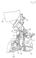
- Fig. 8 shows a third embodiment of the present invention.
- a fuel injection system with a throttle valve 32 is connected to an intake port 16 of an engine mainly responsible for supply of fuel to the engine E, and an additional fuel injection valve 54 is attached between the throttle valve 32 and the air cleaner 29.
- the injection direction of the additional fuel injection valve 54 is set to a direction coincident with a central axis of the narrowed section 31 of the fuel supply system.
- fuel is injected from the additional fuel injection valve 54 towards fuel sucked to the air flow from the respective fuel induction ports 35... at the inside of the narrowed section 31, and it is possible to make the concentration of mixture uniform when the throttle valve 32 is fully open.
- Fig. 9 shows a fourth embodiment of the present invention. While in the third embodiment the injection direction of the additional fuel injection valve 54 is set to a direction coincident with a central axis of the narrowed section 31 of the fuel supply system, in the fourth embodiment the injection direction of the additional fuel injection valve 54 is set so as to pass through the center of a section where the fuel induction ports 35 are provided in the narrowed section 31.
- fuel injected from the additional fuel injection valve 54 is made to collide with fuel sucked from the fuel induction ports 35... without being obstructed by the fully open throttle valve 32 thereby being more effectively dispersed.
- fuel injected from the additional fuel injection valve 54 is made to collide with fuel sucked from the fuel induction ports 35... without being obstructed by the fully open throttle valve 32 thereby being more effectively dispersed.
- a fuel injection valve fitted in an intake path organizer forming an intake path communicating with an air cleaner has a fuel passage for guiding fuel from the fuel injection valve, a fuel induction port having one end communicating with the fuel passage and the other end communicating with the intake path, and an air bleed passageway having one end communicating with the intake path further upstream than the fuel induction port and the other end communicating with the fuel passageway, all provided in the intake path organizer.
- a fuel induction port 35 opens to an intake path 30 in a direction orthogonal to air flow circulating in the intake path 30.
Landscapes
- Engineering & Computer Science (AREA)
- Chemical & Material Sciences (AREA)
- Combustion & Propulsion (AREA)
- Mechanical Engineering (AREA)
- General Engineering & Computer Science (AREA)
- Fuel-Injection Apparatus (AREA)
Abstract
Description
- The present invention relates to an engine fuel supply system, with a fuel injection valve fitted in an intake path organizer forming an intake path communicating with an air cleaner, having a fuel passage for guiding fuel from the fuel injection valve, a fuel induction port having one end communicating with the fuel passage and the other end communicating with the intake path, and an air bleed passageway having one end communicating with the intake path further upstream than the fuel induction port and the other end communicating with the fuel passageway, all provided in the intake path organizer.
- A fuel supply system of the related art is already known, for example, from Japanese Patent Laid-open No. Hei. 5-26132.
- With type of fuel supply system, fuel supplied from a fuel injection valve in an air flow circulating in an intake path is sucked and atomized, and at the same time atomization of the fuel is promoted by assist air from an air bleed passageway. It is possible to cause a reduction in the injection pressure of the fuel injection valve, and there is no need to control fuel injection timing of the fuel injection valve with high precision. However, with the fuel supply system of the related art, the fuel induction port opens facing a downstream side of an air flow inside the intake path, and it is difficult to say that there is favorable atomization of fuel inside the air flow, and it is desirable to significantly promote fuel atomization in order to bring about reduction in fuel consumption, improved exhaust quality, and improved engine output.
- The present invention has been conceived in view of the above described problems, and the object of the present invention is to provide an engine fuel injection system that can promote fuel atomization much more.
- In order to implement the above described object, the invention as disclosed in claim 1 provides an engine fuel supply system, with a fuel injection valve fitted in an intake path organizer forming an intake path communicating with an air cleaner, having a fuel passage for guiding fuel from the fuel injection valve, a fuel induction port having one end communicating with the fuel passage and the other end communicating with the intake path, and an air bleed passageway having one end communicating with the intake path further upstream than the fuel induction port and the other end communicating with the fuel passageway, all provided in the intake path organizer, wherein the other end of the fuel induction port is opened to the intake path in a direction orthogonal to an air flow circulating in the intake path.
- According to the invention of claim 1, the air flow and fuel sucked to the air flow side from the fuel induction port collide with each other because the fuel induction port opens in a direction orthogonal to air flow of the intake path, to effectively atomize the fuel, and by promoting atomization of the fuel it becomes possible to reduce fuel consumption and it also becomes possible to improve exhaust quality and engine output.
- The invention as disclosed in claim 2 is substantially the invention of claim 1, wherein the fuel induction port is provided in the intake path organizer opening to an inner surface of the intake path, and with this construction, it is possible to avoid increasing air-flow resistance without providing a structure that interferes with flow inside the intake path according to the arrangement of the fuel induction port.
- The invention disclosed in
claim 3 is basically the invention of claim 2, wherein the other ends of a plurality of fuel induction ports open to an inner surface of the intake path at mutually opposite positions, and with this construction it becomes possible to prevent fuel sticking to the inner surface of the intake path and to much more effectively atomize the fuel, by causing collision of fuel sucked in to the air flow side from the mutually opposite fuel induction ports, and it is possible to significantly reduce fuel consumption as well as significantly improve exhaust quality and engine output. - The invention disclosed in claim 4 is an engine fuel supply system, with a fuel injection valve fitted in an intake path organizer forming an intake path communicating with an air cleaner, having a fuel passage for guiding fuel from the fuel injection valve, a fuel induction port having one end communicating with the fuel passage and the other end communicating with the intake path, and an air bleed passageway having one end communicating with the intake path further upstream than the fuel induction port and the other end communicating with the fuel passageway, all provided in the intake path organizer, wherein a narrowed section constituting part of the intake path is provided in the intake path organizer with a smaller internal diameter than the intake path at an upstream side of the narrowed section, and the other end of the fuel induction port opens to an inner surface of the narrowed section in a direction orthogonal to an air flow circulating in the narrowed section.
- With the invention of claim 4, by having the fuel induction port opening to an inner surface of a narrowed section in a direction orthogonal to air flow of the intake path, it is possible to more effectively suck fuel to the air flow side from the fuel induction port using negative intake pressure of the narrowed section, it becomes possible to cause collision of the air flow and sucked fuel to more effectively atomize fuel, and it becomes possible to reduce fuel consumption as well as improving exhaust quality and engine output.
- According to the invention as disclosed in claim 1, the air flow of the intake path and fuel sucked to the air flow side from the fuel induction port collide with each other making it possible to effectively atomize the fuel, it becomes possible to reduce fuel consumption and it also becomes possible to improve exhaust quality and engine output.
- According to the invention as disclosed in claim 2, it is possible to avoid increasing ventilation resistance, and it is possible to significantly improve engine output.
- According to the invention as disclosed in
claim 3, it is possible to prevent fuel sticking to the inner surface of the intake path and to much more effectively atomize fuel by causing fuel streams sucked from the mutually opposite fuel induction ports to the air flow side to collide with each other, it is possible to significantly reduce fuel consumption and it is possible to significantly improve exhaust quality and engine output. - According to the invention as disclosed in claim 4, it becomes possible to effectively suck fuel from the fuel induction port to the air flow side using negative intake pressure at the narrowed section, it becomes possible to more effectively atomize fuel by causing air flow of the narrowed section and sucked fuel to collide with each other, it is possible to reduce fuel consumption and it is possible to improve exhaust quality and engine output.
- Embodiments of the present invention will now be described in the following with reference to the attached drawings.
- Fig. 1 is a cut-away cross section showing an engine intake system.
- Fig. 2 is an enlarged vertical cross section of an intake path organizer
- Fig. 3 is a cross section along line 3 - 3 in Fig. 2
- Fig. 4 is a drawing showing a relationship between fuel supply pressure and exhaust quality.
- Fig. 5 is a drawing showing a relationship between fuel injection timing and exhaust quality.
- Fig. 6 is a drawing showing a relationship between brake-mean effective pressure and exhaust quality.
- Fig. 7 is a cross sectional cut-away drawing of an engine intake system of a second embodiment.
- Fig. 8 is a cross sectional cut-away drawing of an engine intake system of a third embodiment.
- Fig. 9 is a cross sectional cut-away drawing of an engine intake system of a fourth embodiment.
-
- A first embodiment of the present invention is shown in Fig. 1 - Fig. 6. Fig. 1 is a cut-away cross section showing an engine intake system, Fig. 2 is an enlarged vertical cross section of an intake path organizer, Fig. 3 is a cross section along line 3 - 3 in Fig. 2, Fig. 4 is a drawing showing a relationship between fuel supply pressure and exhaust quality, Fig. 5 is a drawing showing a relationship between fuel injection timing and exhaust quality, and Fig. 6 is a drawing showing a relationship between brake-mean effective pressure and exhaust quality.
- First of all, in Fig. 1, an engine E comprises a
cylinder block 11 and acylinder head 12 joined to thecylinder block 11, and acombustion chamber 15 is formed between apiston 14 slidably fitted in acylinder bore 13 provided in thecylinder block 11, and thecylinder head 12. - An
intake port 16 and anexhaust port 17 capable of communicating with the combustion chamber are provided in thecylinder head 12, anintake valve 18 for switching between communication and disconnection between theintake port 16 and the combustion chamber, and anexhaust valve 17 for switching between communication and disconnection between the exhaust port and the combustion chamber, are supported in thecylinder head 12 so as to enable opening and closing operations, and theintake valve 18 and theexhaust valve 19 are driven to open and close by aconventional valve mechanism 20. - A
fuel supply system 22 is connected to theintake port 16 via anintake pipe 21. Thisfuel supply system 22 comprises anintake path organizer 23 and afuel injection valve 24 mounted in the intake path organizer. - In Fig. 2, the
intake path organizer 23 is comprised of an intake pathmain component 26 having apassageway 25, and a narrowedsection 27 fixed to the intake pathmain component 26 by fitting into a downstream side of thepassageway 25. The intake pathmain component 23 includes anintake path 30 which has an upper end communicating with anair cleaner 29 via anintake hose 28, and a lower end communicating with theintake pipe 21. Theintake path 30 is comprised of a section for removing sections to which the narrowingmember 27 in thepassageway 25 is fitted, and a narrowedsection 31 formed at an inner surface of the narrowingmember 27. The narrowedsection 31 is formed having a smaller internal diameter than theintake path 30 further upstream than the narrowedsection 31, namely smaller than thepassageway 25. - A butterfly
type throttle valve 32 for controlling the opening extent of theintake path 30 is rotatably supported in the intake pathmain component 26 of the intake path organizer further upstream than the narrowedsection 31. - With reference to Fig. 3, an annular groove is provided around the outer periphery of the narrowing
member 27, and a pair ofannular seal members member 27 is fitted into the intake pathmain component 26, and in a fixed state anannular fuel passage 34 is formed between the narrowingmember 27 and the intake pathmain component 26 using the annular groove, with both sides of thefuel passageway 34 being sealed by theseal members main component 26 and the narrowingmember 27. Specifically, anannular fuel passageway 34 concentrically surrounding theintake path 30 is provided in theintake path organizer 23 at sections corresponding to the narrowedsection 31. - A plurality of, for example four,
fuel induction ports fuel passage 34 and the other end opening to an inner surface of the narrowedsection 31 are provided so that other end opening sections of respectivefuel induction ports fuel induction ports section 31, and other ends of each of thefuel induction ports section 31 in a direction orthogonal to a flow direction of air circulating in the narrowedsection 31. - A
small diameter hole 27 having anend wall 36 at an inner end, anintermediate diameter hole 38, having a larger diameter than thesmall diameter hole 37 and with an inner end leading coaxially to an outer end of thesmall diameter hole 37, and alarge diameter hole 39 having a larger diameter than theintermediate diameter hole 38, an inner end leading coaxially to an outer end of theintermediate hole 38 and with an opening outer end, are provided in the intake pathmain component 26 of theintake path organizer 23, and acylindrical collar 40 having a closed inner end is fitted into thesmall diameter hole 37. - The tip of the
fuel injection valve 24 is inserted into theintermediate diameter hole 38 and thelarge diameter hole 39 with anannular seal member 41 interposed between thelarge diameter hole 39 and the fuel injection valve. A cylindricalfuel squirting nozzle 24a provided at the extreme end of thefuel injection valve 24 is fitted into thecollar 40. - A
bleed chamber 42 is formed between thefuel squirting nozzle 24a and thecollar 40, and thisbleed chamber 42 communicates with thefuel passage 34 through a communicatinghole 43 provided in a tip blocking section of thecollar 40 and a communicatinghole 44 provided in theend wall 36 coaxially with the communicatinghole 43. Anannular seal member 45 is interposed between an outer end of thecollar 40 and thefuel squirting nozzle 24a, and anannular sealing member 46 for pressing against the inner surface of the small diameter hole is fitted onto the outer surface of the inner end of thecollar 40. - An annular recess is provided in an outer surface of a middle part of the
collar 40 for forming anannular chamber 47, between the inner surface of thesmall diameter hole 37 and thecollar 40. A plurality of communicatingholes annular chamber 47 and thebleed chamber 42 are also provided in thecollar 40. - An air bleed
passage 49 having one end leading to theintake path 30 at a point further upstream than each of thefuel induction ports throttle valve 32, is provided in the fuel pathmain component member 26 of thefuel path organizer 23 so that the other end leads to theannular chamber 47, and anair jet 50 is press-fitted into one end of this air bleedpassage 49. Specifically, the other end of the air bleedpassage 40 having one end communicating with theintake path 30 upstream of thethrottle valve 32 communicates with thefuel passage 34 through theannular chamber 47, the communicatingholes bleed chamber 42 and the communicatingholes - Operation of this first embodiment will now be described. Fuel injected from the
fuel injection valve 24 is metered by theair jet 50 inside thebleed chamber 42, mixed with assist air supplied from the air bleedpassage 49 and guided to thefuel passage 34. The fuel is then sucked from thefuel induction ports intake path 30 by an air flow circulating in theintake path 30 and atomized. Also, each of thefuel induction ports intake path 30 in a direction orthogonal to the air flow circulating in theintake path 30, and the fuel is effectively atomized because of collision between the air flow circulating in theintake path 30 and the fuel sucked to the air flow side from thefuel induction holes - Since the
fuel induction holes intake path 30, no structure disturbing flow inside theintake path 30 accompanying arrangement of thefuel induction ports - The
fuel induction ports intake path 30 at positions opposite to each other, which means that by causing collision between respective fuel streams sucked to the air flow side from the mutually oppositefuel induction holes intake path 30, it becomes possible to significantly reduce fuel consumption and it is possible to improve exhaust quality and engine output. - In particular, the narrowed
section 31 constituting part of theintake path 30 is provided in theintake path organizer 23 having an internal diameter smaller than theintake path 30 further upstream than the narrowedsection 31, and thefuel induction holes section 31 in directions orthogonal to air flow circulating in the narrowedsection 31, which means that it becomes possible to more effectively suck fuel from thefuel induction holes section 31, it becomes possible to significantly reduce fuel consumption and it is possible to improve exhaust quality and engine output. - In Fig. 4, exhaust quality of the
fuel supply system 22 of the present invention and exhaust quality of a fuel supply system using only fuel injection from a fuel injection valve are compared with variation in fuel supply pressure under running conditions of engine speed of 4000 rpm and brake mean effective pressure Pme of 400 kPa. With thefuel supply system 22 using only fuel injected from a fuel injection valve, fuel supply pressure has a lower limit threshold of 250 kPa, while thefuel supply system 22 of the present invention can produce fuel spray which can suppress HC concentration in the exhaust gas limited to about 180 ppm, which is about the same as a conventional carburetor, even if the fuel supply pressure to the fuel injection valve is reduced to 0 kPa. Specifically, thefuel supply system 22 of the present invention makes it possible to sufficiently atomize fuel even if the fuel supply pressure is reduced to almost 0 kPa, whereas sufficient atomization of the fuel is not obtained with the fuel supply system using only fuel injection from a fuel injection valve unless the fuel supply pressure is set to at least 250 kPa. - Accordingly, it is possible to make a fuel pump connected to the
fuel injection valve 24 small in size, and to reduce power consumption, and it is also possible to reduce the cost of fuel piping provided between thefuel injection valve 24 and the fuel pump. Instead of using the fuel pump, it is also possible to supply fuel to thefuel injection valve 24 using only head pressure from a fuel tank arranged above thefuel injection valve 24, and to meter fuel by turning thefuel injection valve 24 on and off. - Because it is possible to perform adequate fuel atomization in this way, it becomes possible to shorten the length of an intake pipe from the
fuel passage organizer 22 to theintake port 16, and it is possible to reduce the overall size of an engine including the intake system. - The
fuel injection valve 24 can be fitted into theintake path organizer 23 with any orientation as long as fuel is supplied to thefuel passage 34, so it is possible to increase the degree of freedom with respect to arranging thefuel injection valve 24. However, if thefuel injection valve 24 is fitted so that it is orthogonal to theintake path 30 as in this embodiment, it is possible to reduce the overall size of the engine including the intake system by shortening the intake system. - Fig. 5 shows a comparison of exhaust quality of the
fuel supply system 22 of the present invention and exhaust quality of a fuel supply system using only fuel injected from a fuel injection valve under running conditions of engine speed of 4000 rpm and brake mean effective pressure Pme of 400 kPa with variation in fuel injection timing (crank angle before OTDC). As is clear from Fig. 5, there is no variation in exhaust quality with thefuel supply system 22 of the present invention even if the injection timing of thefuel injection valve 24 is varied, while the exhaust quality varies according to variation in injection timing with thefuel supply system 22 using only fuel injection from a fuel injection valve. Specifically, with thefuel supply system 22 of the present invention, fuel is metered using intake negative pressure according to running conditions of the engine E and sucked into theintake path 30, and thefuel injection valve 24 preferably supplies fuel according to the amount of fuel sucked to theintake path 30, which means that it is possible to sufficiently atomize the fuel and obtain good exhaust quality without controlling injection timing of thefuel injection valve 24 with high precision. However, with fuel supply using only fuel injection from a fuel injection valve, adequate fuel atomization is not obtained unless the fuel injection timing is controlled with high precision and exhaust quality is bad. - Fig. 6 shows a comparison of exhaust quality of the
fuel supply system 22 of the present invention and exhaust quality of a fuel supply system using only fuel injection from a fuel injection valve under low engine running conditions of 2000 rpm with variation in brake mean effective pressure Pme. As is clear from Fig. 6, with thefuel supply system 22 of the present invention, when brake mean effective pressure Pme is low, namely when the engine is running at a low speed of 2000 rpm or at high load, fuel is sufficiently atomized and good exhaust quality is obtained, compared to the fuel system using only fuel injection from a fuel injection valve that can not sufficiently atomize the fuel leading to degradation of exhaust quality. Specifically, with thefuel supply system 22 of the present invention atomization is also carried out using assist air, which means that it is possible to sufficiently atomize the fuel even under high load, low speed running conditions. - In a conventional engine in which fuel is supplied using a fuel injection valve, it is difficult to handle fuel supply over a wide driving range from idle opening of the throttle valve to fully open, with a single fuel injection valve, and an additional fuel injection valve is arranged upstream of the throttle valve, but it is possible to use the fuel supply system of the present invention instead of the additional fuel injection valve, and the intake system in this type of situation will now be described in a second embodiment.
- In Fig. 7, a
fuel injection valve 52 for mainly handling fuel to be supplied to an engine E is attached to anintake pipe 53 connected to anintake port 16 of the engine E, and the intake pipe is connected to anair cleaner 29 through a throttle body provided with a throttle valve, and a fuel supply system 22'. - The fuel supply system 22' has the same structure as the
fuel supply system 22 of the first embodiment described above except for the fact that the throttle valve is not provided, and supplements fuel when an amount of fuel injected from thefuel injection valve 52 is insufficient. - According to the second embodiment, it is possible to avoid increasing intake resistance due to the fuel supply system 22' regardless of the fact that the fuel system 22' is arranged upstream of the
throttle valve 23 in place of the additional fuel injection valve. - Fig. 8 shows a third embodiment of the present invention. A fuel injection system with a
throttle valve 32 is connected to anintake port 16 of an engine mainly responsible for supply of fuel to the engine E, and an additionalfuel injection valve 54 is attached between thethrottle valve 32 and theair cleaner 29. - The injection direction of the additional
fuel injection valve 54 is set to a direction coincident with a central axis of the narrowedsection 31 of the fuel supply system. - According to the third embodiment, in the
fuel supply system 22 fuel is injected from the additionalfuel injection valve 54 towards fuel sucked to the air flow from the respectivefuel induction ports 35... at the inside of the narrowedsection 31, and it is possible to make the concentration of mixture uniform when thethrottle valve 32 is fully open. - Fig. 9 shows a fourth embodiment of the present invention. While in the third embodiment the injection direction of the additional
fuel injection valve 54 is set to a direction coincident with a central axis of the narrowedsection 31 of the fuel supply system, in the fourth embodiment the injection direction of the additionalfuel injection valve 54 is set so as to pass through the center of a section where thefuel induction ports 35 are provided in the narrowedsection 31. - According to the fourth embodiment, fuel injected from the additional
fuel injection valve 54 is made to collide with fuel sucked from thefuel induction ports 35... without being obstructed by the fullyopen throttle valve 32 thereby being more effectively dispersed. As a result it is possible to make air-fuel mixture concentration extremely uniform - Embodiments of the present invention have been described in detail above, but the present invention is not limited to these embodiments and various design changes can be carried out without departing from the spirit and scope of the present invention as defined in the attached claims.
- To promote atomization of fuel in an engine fuel supply system, a fuel injection valve fitted in an intake path organizer forming an intake path communicating with an air cleaner has a fuel passage for guiding fuel from the fuel injection valve, a fuel induction port having one end communicating with the fuel passage and the other end communicating with the intake path, and an air bleed passageway having one end communicating with the intake path further upstream than the fuel induction port and the other end communicating with the fuel passageway, all provided in the intake path organizer.
- A
fuel induction port 35 opens to anintake path 30 in a direction orthogonal to air flow circulating in theintake path 30.
Claims (4)
- An engine fuel supply system, with a fuel injection valve (24) fitted in an intake path organizer (23) forming an intake path (30) communicating with an air cleaner (29), having a fuel passage (34) for guiding fuel from the fuel injection valve (24), a fuel induction port (35) having one end communicating with the fuel passage (34) and the other end communicating with the intake path (30), and an air bleed passageway (49) having one end communicating with the intake path (30) further upstream than the fuel induction port (35) and the other end communicating with the fuel passageway (34), all provided in the intake path organizer (23), wherein the other end of the fuel induction port (35) is opened to the intake path (30) in a direction orthogonal to an air flow circulating in the intake path (30).
- The engine fuel supply system of claim 1, wherein the fuel induction port (35) is provided in the intake path organizer (23) opening to an inner surface of the intake path (30).
- The engine fuel supply system of claim 2, wherein the other ends of a plurality of fuel induction ports (35) open to an inner surface of the intake path at mutually opposite positions.
- An engine fuel supply system, with a fuel injection valve (24) fitted in an intake path organizer (23) forming an intake path (30) communicating with an air cleaner (29), having a fuel passage (34) for guiding fuel from the fuel injection valve (24), a fuel induction port (35) having one end communicating with the fuel passage (34) and the other end communicating with the intake path (30), and an air bleed passageway (49) having one end communicating with the intake path (30) further upstream than the fuel induction port (35) and the other end communicating with the fuel passageway (34), all provided in the intake path organizer (23), wherein a narrowed section (31) constituting part of the intake path (30) is provided in the intake path organizer (23) with a smaller internal diameter than the intake path (30) at an upstream side of the narrowed section(31), and the other end of the fuel induction port (35) opens to an inner surface of the narrowed section (31) in a direction orthogonal to an air flow circulating in the narrowed section (31).
Applications Claiming Priority (2)
| Application Number | Priority Date | Filing Date | Title |
|---|---|---|---|
| JP31146999 | 1999-11-01 | ||
| JP31146999A JP2001132589A (en) | 1999-11-01 | 1999-11-01 | Engine fuel supply |
Publications (3)
| Publication Number | Publication Date |
|---|---|
| EP1096138A2 true EP1096138A2 (en) | 2001-05-02 |
| EP1096138A3 EP1096138A3 (en) | 2003-10-22 |
| EP1096138B1 EP1096138B1 (en) | 2004-09-15 |
Family
ID=18017608
Family Applications (1)
| Application Number | Title | Priority Date | Filing Date |
|---|---|---|---|
| EP00123581A Expired - Lifetime EP1096138B1 (en) | 1999-11-01 | 2000-10-27 | Engine fuel supply system |
Country Status (7)
| Country | Link |
|---|---|
| US (1) | US6453888B1 (en) |
| EP (1) | EP1096138B1 (en) |
| JP (1) | JP2001132589A (en) |
| CN (1) | CN1127617C (en) |
| AU (1) | AU768946B2 (en) |
| DE (1) | DE60013730T2 (en) |
| TW (1) | TW480316B (en) |
Cited By (13)
| Publication number | Priority date | Publication date | Assignee | Title |
|---|---|---|---|---|
| EP1403507A1 (en) | 2002-09-11 | 2004-03-31 | Honda Giken Kogyo Kabushiki Kaisha | Engine fuel injection apparatus |
| EP1464824A1 (en) * | 2003-03-31 | 2004-10-06 | HONDA MOTOR CO., Ltd. | Fuel injection system for engine in small-type vehicle |
| FR2879518A1 (en) * | 2004-12-20 | 2006-06-23 | Renault Sas | AIR INTAKE DUCT ARRANGEMENT OF AN INTERNAL COMBUSTION ENGINE |
| EP1698779A1 (en) * | 2005-03-02 | 2006-09-06 | Keihin Corporation | Structure of fuel supply pipe in throttle body comprising two fuel injection valves |
| US7216627B2 (en) | 2005-03-18 | 2007-05-15 | Toyota Jidosha Kabushiki Kaisha | Internal combustion engine provided with double system of fuel injection |
| US7281517B2 (en) | 2005-03-18 | 2007-10-16 | Yamaha Hatsudoki Kabushiki Kaisha | Internal combustion engine provided with double system of fuel injection |
| US7296558B2 (en) | 2005-03-18 | 2007-11-20 | Yamaha Hatsudoki Kabushiki Kaisha | Dual-injector fuel injection engine |
| US7299784B2 (en) | 2005-03-18 | 2007-11-27 | Toyota Jidosha Kabushiki Kaisha | Internal combustion engine |
| WO2009034342A3 (en) * | 2007-09-14 | 2009-06-04 | Scion Sprays Ltd | A fuel injection system for an internal combustion engine |
| US7637242B2 (en) | 2004-03-22 | 2009-12-29 | Yamaha Motor Co., Ltd. | Fuel supply system and vehicle |
| EP2295776A3 (en) * | 2005-08-05 | 2017-06-21 | Robert Bosch GmbH | Fuel injection unit |
| WO2017177992A1 (en) * | 2016-04-13 | 2017-10-19 | Alkoma Trade A.S. | Charged internal combustion engine |
| US20210156347A1 (en) * | 2019-11-25 | 2021-05-27 | Miles John Zock | System for enhancing performance of carburetor engine and peripherals of an all-terrain vehicle |
Families Citing this family (8)
| Publication number | Priority date | Publication date | Assignee | Title |
|---|---|---|---|---|
| US6935099B2 (en) * | 2001-08-31 | 2005-08-30 | Honda Giken Kogyo Kabushiki Kaisha | Deteriorated state evaluation device of exhaust emission control equipment |
| WO2005098231A1 (en) | 2004-03-30 | 2005-10-20 | Yamaha Hatsudoki Kabushiki Kaisha | Saddle ride-type motor vehicle |
| JP4422062B2 (en) * | 2005-04-11 | 2010-02-24 | 株式会社ケーヒン | Fuel injection device |
| US7096849B1 (en) * | 2005-07-12 | 2006-08-29 | Steeda Autosports, Inc. | Charge motion control plate kit |
| EP2604843B1 (en) * | 2011-12-13 | 2020-06-10 | Caterpillar Motoren GmbH & Co. KG | Cylinder head with fuel guiding portion |
| DE102017114213B4 (en) * | 2017-06-27 | 2024-08-14 | Dr. Ing. H.C. F. Porsche Aktiengesellschaft | Water injection valve arrangement |
| CN113795659B (en) * | 2019-05-03 | 2024-03-26 | 沃尔布罗有限责任公司 | Inflation forming device with throttle valve |
| CN115298431A (en) * | 2020-03-26 | 2022-11-04 | Tvs电机股份有限公司 | Power unit and air inlet component thereof |
Citations (1)
| Publication number | Priority date | Publication date | Assignee | Title |
|---|---|---|---|---|
| JPH0526132A (en) | 1991-07-16 | 1993-02-02 | Keihin Seiki Mfg Co Ltd | Fuel injector |
Family Cites Families (5)
| Publication number | Priority date | Publication date | Assignee | Title |
|---|---|---|---|---|
| JPS5677634U (en) * | 1979-11-22 | 1981-06-24 | ||
| JPS56133964U (en) * | 1980-03-12 | 1981-10-12 | ||
| DE4002340A1 (en) * | 1990-02-02 | 1991-08-01 | N I S Pri Vtu Angel Kantschev | DEVICE FOR MIXING AIR AND GAS OR VAPORED FUELS |
| AUPN286095A0 (en) * | 1995-05-09 | 1995-06-01 | Energy Research And Development Corporation, The | Liquid fuel injection system |
| US5908475A (en) * | 1996-01-02 | 1999-06-01 | Cummins Engine Company, Inc. | Gas/air mixer |
-
1999
- 1999-11-01 JP JP31146999A patent/JP2001132589A/en active Pending
-
2000
- 2000-10-03 AU AU62442/00A patent/AU768946B2/en not_active Ceased
- 2000-10-11 TW TW089121188A patent/TW480316B/en not_active IP Right Cessation
- 2000-10-25 CN CN00131958.2A patent/CN1127617C/en not_active Expired - Fee Related
- 2000-10-27 EP EP00123581A patent/EP1096138B1/en not_active Expired - Lifetime
- 2000-10-27 DE DE60013730T patent/DE60013730T2/en not_active Expired - Fee Related
- 2000-11-01 US US09/702,901 patent/US6453888B1/en not_active Expired - Fee Related
Patent Citations (1)
| Publication number | Priority date | Publication date | Assignee | Title |
|---|---|---|---|---|
| JPH0526132A (en) | 1991-07-16 | 1993-02-02 | Keihin Seiki Mfg Co Ltd | Fuel injector |
Cited By (22)
| Publication number | Priority date | Publication date | Assignee | Title |
|---|---|---|---|---|
| US7100575B2 (en) | 2002-09-11 | 2006-09-05 | Honda Giken Kogyo Kabushiki Kaisha | Engine fuel injection apparatus |
| US7013874B2 (en) | 2002-09-11 | 2006-03-21 | Honda Giken Kogyo Kabushiki Kaisha | Engine fuel injection apparatus |
| EP1403507A1 (en) | 2002-09-11 | 2004-03-31 | Honda Giken Kogyo Kabushiki Kaisha | Engine fuel injection apparatus |
| EP1464824A1 (en) * | 2003-03-31 | 2004-10-06 | HONDA MOTOR CO., Ltd. | Fuel injection system for engine in small-type vehicle |
| US7028669B2 (en) | 2003-03-31 | 2006-04-18 | Honda Motor Co., Ltd. | Fuel injection system for engine in small-type vehicle |
| US7637242B2 (en) | 2004-03-22 | 2009-12-29 | Yamaha Motor Co., Ltd. | Fuel supply system and vehicle |
| WO2006067342A3 (en) * | 2004-12-20 | 2006-08-31 | Renault Sa | Air intake duct arrangement for an internal combustion engine |
| JP2008524514A (en) * | 2004-12-20 | 2008-07-10 | ルノー・エス・アー・エス | Configuration of air intake duct for internal combustion engine |
| US7628132B2 (en) | 2004-12-20 | 2009-12-08 | Renault S.A.S. | Air intake duct arrangement for an internal combustion engine |
| FR2879518A1 (en) * | 2004-12-20 | 2006-06-23 | Renault Sas | AIR INTAKE DUCT ARRANGEMENT OF AN INTERNAL COMBUSTION ENGINE |
| EP1698779A1 (en) * | 2005-03-02 | 2006-09-06 | Keihin Corporation | Structure of fuel supply pipe in throttle body comprising two fuel injection valves |
| US7216627B2 (en) | 2005-03-18 | 2007-05-15 | Toyota Jidosha Kabushiki Kaisha | Internal combustion engine provided with double system of fuel injection |
| US7281517B2 (en) | 2005-03-18 | 2007-10-16 | Yamaha Hatsudoki Kabushiki Kaisha | Internal combustion engine provided with double system of fuel injection |
| US7296558B2 (en) | 2005-03-18 | 2007-11-20 | Yamaha Hatsudoki Kabushiki Kaisha | Dual-injector fuel injection engine |
| US7299784B2 (en) | 2005-03-18 | 2007-11-27 | Toyota Jidosha Kabushiki Kaisha | Internal combustion engine |
| EP2295776A3 (en) * | 2005-08-05 | 2017-06-21 | Robert Bosch GmbH | Fuel injection unit |
| WO2009034342A3 (en) * | 2007-09-14 | 2009-06-04 | Scion Sprays Ltd | A fuel injection system for an internal combustion engine |
| GB2465740B (en) * | 2007-09-14 | 2013-08-07 | Scion Sprays Ltd | A fuel injection system for an internal combustion engine |
| GB2465740A (en) * | 2007-09-14 | 2010-06-02 | Scion Sprays Ltd | A fuel injection system for an internal combustion engine |
| WO2017177992A1 (en) * | 2016-04-13 | 2017-10-19 | Alkoma Trade A.S. | Charged internal combustion engine |
| US20210156347A1 (en) * | 2019-11-25 | 2021-05-27 | Miles John Zock | System for enhancing performance of carburetor engine and peripherals of an all-terrain vehicle |
| US11624343B2 (en) * | 2019-11-25 | 2023-04-11 | Zoom Zoom Parts Llc | System for enhancing performance of carburetor engine and peripherals of an all-terrain vehicle |
Also Published As
| Publication number | Publication date |
|---|---|
| DE60013730T2 (en) | 2005-01-27 |
| AU6244200A (en) | 2001-05-03 |
| US6453888B1 (en) | 2002-09-24 |
| CN1302949A (en) | 2001-07-11 |
| EP1096138B1 (en) | 2004-09-15 |
| TW480316B (en) | 2002-03-21 |
| DE60013730D1 (en) | 2004-10-21 |
| AU768946B2 (en) | 2004-01-08 |
| EP1096138A3 (en) | 2003-10-22 |
| CN1127617C (en) | 2003-11-12 |
| JP2001132589A (en) | 2001-05-15 |
Similar Documents
| Publication | Publication Date | Title |
|---|---|---|
| EP1096138B1 (en) | Engine fuel supply system | |
| US8281766B2 (en) | Mount structure of fuel injection valve and fuel injection system | |
| JPS5950850B2 (en) | Internal combustion engine intake system | |
| CN101360912B (en) | Mounting structure of fuel injection valve and fuel injection system | |
| JPH076395B2 (en) | Internal combustion engine intake system | |
| JPH0424548B2 (en) | ||
| US5301879A (en) | Fuel injection device for an internal combustion engine | |
| JPH08296535A (en) | Internal combustion engine intake system | |
| US4530325A (en) | Suction system for internal combustion engine | |
| JPH05340326A (en) | Fuel supply device for internal combustion engine | |
| JPH10103196A (en) | Multi intake valve type engine | |
| JP2000265906A (en) | Acceleration device for evaporator | |
| EP0891485B1 (en) | Carburetor with fuel nozzle | |
| JPS628627B2 (en) | ||
| KR0134202Y1 (en) | Double intake injector | |
| JPH0634612Y2 (en) | Combustion injection device for internal combustion engine | |
| JPS62223456A (en) | Fuel injection type internal combustion engine | |
| JPS588230A (en) | Suction device for multi-cylinder internal combustion engine | |
| JPS5851375Y2 (en) | Internal combustion engine intake system | |
| JPH0118839Y2 (en) | ||
| JPH0442528Y2 (en) | ||
| JPS59208149A (en) | Carbureter for internal-combustion engine | |
| JP2002202005A (en) | Slow passage for carburetor | |
| JPS6149496B2 (en) | ||
| JPS61226563A (en) | Fuel injection device for engine |
Legal Events
| Date | Code | Title | Description |
|---|---|---|---|
| PUAI | Public reference made under article 153(3) epc to a published international application that has entered the european phase |
Free format text: ORIGINAL CODE: 0009012 |
|
| AK | Designated contracting states |
Kind code of ref document: A2 Designated state(s): AT BE CH CY DE DK ES FI FR GB GR IE IT LI LU MC NL PT SE |
|
| AX | Request for extension of the european patent |
Free format text: AL;LT;LV;MK;RO;SI |
|
| PUAL | Search report despatched |
Free format text: ORIGINAL CODE: 0009013 |
|
| AK | Designated contracting states |
Kind code of ref document: A3 Designated state(s): AT BE CH CY DE DK ES FI FR GB GR IE IT LI LU MC NL PT SE |
|
| AX | Request for extension of the european patent |
Extension state: AL LT LV MK RO SI |
|
| 17P | Request for examination filed |
Effective date: 20031007 |
|
| 17Q | First examination report despatched |
Effective date: 20031121 |
|
| GRAP | Despatch of communication of intention to grant a patent |
Free format text: ORIGINAL CODE: EPIDOSNIGR1 |
|
| GRAS | Grant fee paid |
Free format text: ORIGINAL CODE: EPIDOSNIGR3 |
|
| AKX | Designation fees paid |
Designated state(s): DE FR GB |
|
| GRAA | (expected) grant |
Free format text: ORIGINAL CODE: 0009210 |
|
| AK | Designated contracting states |
Kind code of ref document: B1 Designated state(s): DE FR GB |
|
| REG | Reference to a national code |
Ref country code: GB Ref legal event code: FG4D |
|
| REG | Reference to a national code |
Ref country code: IE Ref legal event code: FG4D |
|
| REF | Corresponds to: |
Ref document number: 60013730 Country of ref document: DE Date of ref document: 20041021 Kind code of ref document: P |
|
| ET | Fr: translation filed | ||
| PLBE | No opposition filed within time limit |
Free format text: ORIGINAL CODE: 0009261 |
|
| STAA | Information on the status of an ep patent application or granted ep patent |
Free format text: STATUS: NO OPPOSITION FILED WITHIN TIME LIMIT |
|
| 26N | No opposition filed |
Effective date: 20050616 |
|
| PGFP | Annual fee paid to national office [announced via postgrant information from national office to epo] |
Ref country code: DE Payment date: 20061019 Year of fee payment: 7 |
|
| PGFP | Annual fee paid to national office [announced via postgrant information from national office to epo] |
Ref country code: GB Payment date: 20061025 Year of fee payment: 7 |
|
| PGFP | Annual fee paid to national office [announced via postgrant information from national office to epo] |
Ref country code: FR Payment date: 20071009 Year of fee payment: 8 |
|
| GBPC | Gb: european patent ceased through non-payment of renewal fee |
Effective date: 20071027 |
|
| PG25 | Lapsed in a contracting state [announced via postgrant information from national office to epo] |
Ref country code: DE Free format text: LAPSE BECAUSE OF NON-PAYMENT OF DUE FEES Effective date: 20080501 |
|
| PG25 | Lapsed in a contracting state [announced via postgrant information from national office to epo] |
Ref country code: GB Free format text: LAPSE BECAUSE OF NON-PAYMENT OF DUE FEES Effective date: 20071027 |
|
| REG | Reference to a national code |
Ref country code: FR Ref legal event code: ST Effective date: 20090630 |
|
| PG25 | Lapsed in a contracting state [announced via postgrant information from national office to epo] |
Ref country code: FR Free format text: LAPSE BECAUSE OF NON-PAYMENT OF DUE FEES Effective date: 20081031 |