EP1096134A2 - Wiring harness assembly for an intake manifold - Google Patents
Wiring harness assembly for an intake manifold Download PDFInfo
- Publication number
- EP1096134A2 EP1096134A2 EP00203707A EP00203707A EP1096134A2 EP 1096134 A2 EP1096134 A2 EP 1096134A2 EP 00203707 A EP00203707 A EP 00203707A EP 00203707 A EP00203707 A EP 00203707A EP 1096134 A2 EP1096134 A2 EP 1096134A2
- Authority
- EP
- European Patent Office
- Prior art keywords
- assembly
- foam
- flexible circuit
- intake manifold
- layers
- Prior art date
- Legal status (The legal status is an assumption and is not a legal conclusion. Google has not performed a legal analysis and makes no representation as to the accuracy of the status listed.)
- Granted
Links
Images
Classifications
-
- F—MECHANICAL ENGINEERING; LIGHTING; HEATING; WEAPONS; BLASTING
- F02—COMBUSTION ENGINES; HOT-GAS OR COMBUSTION-PRODUCT ENGINE PLANTS
- F02M—SUPPLYING COMBUSTION ENGINES IN GENERAL WITH COMBUSTIBLE MIXTURES OR CONSTITUENTS THEREOF
- F02M35/00—Combustion-air cleaners, air intakes, intake silencers, or induction systems specially adapted for, or arranged on, internal-combustion engines
- F02M35/10—Air intakes; Induction systems
- F02M35/10314—Materials for intake systems
- F02M35/10321—Plastics; Composites; Rubbers
-
- B—PERFORMING OPERATIONS; TRANSPORTING
- B60—VEHICLES IN GENERAL
- B60R—VEHICLES, VEHICLE FITTINGS, OR VEHICLE PARTS, NOT OTHERWISE PROVIDED FOR
- B60R16/00—Electric or fluid circuits specially adapted for vehicles and not otherwise provided for; Arrangement of elements of electric or fluid circuits specially adapted for vehicles and not otherwise provided for
- B60R16/02—Electric or fluid circuits specially adapted for vehicles and not otherwise provided for; Arrangement of elements of electric or fluid circuits specially adapted for vehicles and not otherwise provided for electric constitutive elements
- B60R16/0207—Wire harnesses
-
- F—MECHANICAL ENGINEERING; LIGHTING; HEATING; WEAPONS; BLASTING
- F02—COMBUSTION ENGINES; HOT-GAS OR COMBUSTION-PRODUCT ENGINE PLANTS
- F02B—INTERNAL-COMBUSTION PISTON ENGINES; COMBUSTION ENGINES IN GENERAL
- F02B75/00—Other engines
- F02B75/16—Engines characterised by number of cylinders, e.g. single-cylinder engines
- F02B75/18—Multi-cylinder engines
- F02B75/22—Multi-cylinder engines with cylinders in V, fan, or star arrangement
-
- F—MECHANICAL ENGINEERING; LIGHTING; HEATING; WEAPONS; BLASTING
- F02—COMBUSTION ENGINES; HOT-GAS OR COMBUSTION-PRODUCT ENGINE PLANTS
- F02D—CONTROLLING COMBUSTION ENGINES
- F02D41/00—Electrical control of supply of combustible mixture or its constituents
- F02D41/30—Controlling fuel injection
- F02D41/3005—Details not otherwise provided for
-
- F—MECHANICAL ENGINEERING; LIGHTING; HEATING; WEAPONS; BLASTING
- F02—COMBUSTION ENGINES; HOT-GAS OR COMBUSTION-PRODUCT ENGINE PLANTS
- F02M—SUPPLYING COMBUSTION ENGINES IN GENERAL WITH COMBUSTIBLE MIXTURES OR CONSTITUENTS THEREOF
- F02M35/00—Combustion-air cleaners, air intakes, intake silencers, or induction systems specially adapted for, or arranged on, internal-combustion engines
- F02M35/10—Air intakes; Induction systems
- F02M35/10209—Fluid connections to the air intake system; their arrangement of pipes, valves or the like
- F02M35/10216—Fuel injectors; Fuel pipes or rails; Fuel pumps or pressure regulators
-
- F—MECHANICAL ENGINEERING; LIGHTING; HEATING; WEAPONS; BLASTING
- F02—COMBUSTION ENGINES; HOT-GAS OR COMBUSTION-PRODUCT ENGINE PLANTS
- F02M—SUPPLYING COMBUSTION ENGINES IN GENERAL WITH COMBUSTIBLE MIXTURES OR CONSTITUENTS THEREOF
- F02M35/00—Combustion-air cleaners, air intakes, intake silencers, or induction systems specially adapted for, or arranged on, internal-combustion engines
- F02M35/10—Air intakes; Induction systems
- F02M35/10242—Devices or means connected to or integrated into air intakes; Air intakes combined with other engine or vehicle parts
- F02M35/10249—Electrical or electronic devices fixed to the intake system; Electric wiring
-
- F—MECHANICAL ENGINEERING; LIGHTING; HEATING; WEAPONS; BLASTING
- F02—COMBUSTION ENGINES; HOT-GAS OR COMBUSTION-PRODUCT ENGINE PLANTS
- F02M—SUPPLYING COMBUSTION ENGINES IN GENERAL WITH COMBUSTIBLE MIXTURES OR CONSTITUENTS THEREOF
- F02M35/00—Combustion-air cleaners, air intakes, intake silencers, or induction systems specially adapted for, or arranged on, internal-combustion engines
- F02M35/10—Air intakes; Induction systems
- F02M35/10242—Devices or means connected to or integrated into air intakes; Air intakes combined with other engine or vehicle parts
- F02M35/10268—Heating, cooling or thermal insulating means
-
- F—MECHANICAL ENGINEERING; LIGHTING; HEATING; WEAPONS; BLASTING
- F02—COMBUSTION ENGINES; HOT-GAS OR COMBUSTION-PRODUCT ENGINE PLANTS
- F02M—SUPPLYING COMBUSTION ENGINES IN GENERAL WITH COMBUSTIBLE MIXTURES OR CONSTITUENTS THEREOF
- F02M35/00—Combustion-air cleaners, air intakes, intake silencers, or induction systems specially adapted for, or arranged on, internal-combustion engines
- F02M35/10—Air intakes; Induction systems
- F02M35/10242—Devices or means connected to or integrated into air intakes; Air intakes combined with other engine or vehicle parts
- F02M35/10288—Air intakes combined with another engine part, e.g. cylinder head cover or being cast in one piece with the exhaust manifold, cylinder head or engine block
-
- F—MECHANICAL ENGINEERING; LIGHTING; HEATING; WEAPONS; BLASTING
- F02—COMBUSTION ENGINES; HOT-GAS OR COMBUSTION-PRODUCT ENGINE PLANTS
- F02M—SUPPLYING COMBUSTION ENGINES IN GENERAL WITH COMBUSTIBLE MIXTURES OR CONSTITUENTS THEREOF
- F02M35/00—Combustion-air cleaners, air intakes, intake silencers, or induction systems specially adapted for, or arranged on, internal-combustion engines
- F02M35/10—Air intakes; Induction systems
- F02M35/10242—Devices or means connected to or integrated into air intakes; Air intakes combined with other engine or vehicle parts
- F02M35/10301—Flexible, resilient, pivotally or movable parts; Membranes
-
- F—MECHANICAL ENGINEERING; LIGHTING; HEATING; WEAPONS; BLASTING
- F02—COMBUSTION ENGINES; HOT-GAS OR COMBUSTION-PRODUCT ENGINE PLANTS
- F02M—SUPPLYING COMBUSTION ENGINES IN GENERAL WITH COMBUSTIBLE MIXTURES OR CONSTITUENTS THEREOF
- F02M35/00—Combustion-air cleaners, air intakes, intake silencers, or induction systems specially adapted for, or arranged on, internal-combustion engines
- F02M35/10—Air intakes; Induction systems
- F02M35/10314—Materials for intake systems
- F02M35/10334—Foams; Fabrics; Porous media; Laminates; Ceramics; Coatings
-
- F—MECHANICAL ENGINEERING; LIGHTING; HEATING; WEAPONS; BLASTING
- F02—COMBUSTION ENGINES; HOT-GAS OR COMBUSTION-PRODUCT ENGINE PLANTS
- F02M—SUPPLYING COMBUSTION ENGINES IN GENERAL WITH COMBUSTIBLE MIXTURES OR CONSTITUENTS THEREOF
- F02M35/00—Combustion-air cleaners, air intakes, intake silencers, or induction systems specially adapted for, or arranged on, internal-combustion engines
- F02M35/10—Air intakes; Induction systems
- F02M35/104—Intake manifolds
- F02M35/116—Intake manifolds for engines with cylinders in V-arrangement or arranged oppositely relative to the main shaft
- F02M35/1165—Boxer or pancake engines
-
- F—MECHANICAL ENGINEERING; LIGHTING; HEATING; WEAPONS; BLASTING
- F02—COMBUSTION ENGINES; HOT-GAS OR COMBUSTION-PRODUCT ENGINE PLANTS
- F02M—SUPPLYING COMBUSTION ENGINES IN GENERAL WITH COMBUSTIBLE MIXTURES OR CONSTITUENTS THEREOF
- F02M35/00—Combustion-air cleaners, air intakes, intake silencers, or induction systems specially adapted for, or arranged on, internal-combustion engines
- F02M35/16—Combustion-air cleaners, air intakes, intake silencers, or induction systems specially adapted for, or arranged on, internal-combustion engines characterised by use in vehicles
- F02M35/161—Arrangement of the air intake system in the engine compartment, e.g. with respect to the bonnet or the vehicle front face
-
- H—ELECTRICITY
- H05—ELECTRIC TECHNIQUES NOT OTHERWISE PROVIDED FOR
- H05K—PRINTED CIRCUITS; CASINGS OR CONSTRUCTIONAL DETAILS OF ELECTRIC APPARATUS; MANUFACTURE OF ASSEMBLAGES OF ELECTRICAL COMPONENTS
- H05K1/00—Printed circuits
- H05K1/02—Details
- H05K1/0277—Bendability or stretchability details
- H05K1/028—Bending or folding regions of flexible printed circuits
-
- F—MECHANICAL ENGINEERING; LIGHTING; HEATING; WEAPONS; BLASTING
- F02—COMBUSTION ENGINES; HOT-GAS OR COMBUSTION-PRODUCT ENGINE PLANTS
- F02D—CONTROLLING COMBUSTION ENGINES
- F02D2400/00—Control systems adapted for specific engine types; Special features of engine control systems not otherwise provided for; Power supply, connectors or cabling for engine control systems
- F02D2400/18—Packaging of the electronic circuit in a casing
-
- F—MECHANICAL ENGINEERING; LIGHTING; HEATING; WEAPONS; BLASTING
- F02—COMBUSTION ENGINES; HOT-GAS OR COMBUSTION-PRODUCT ENGINE PLANTS
- F02D—CONTROLLING COMBUSTION ENGINES
- F02D2400/00—Control systems adapted for specific engine types; Special features of engine control systems not otherwise provided for; Power supply, connectors or cabling for engine control systems
- F02D2400/22—Connectors or cables specially adapted for engine management applications
-
- F—MECHANICAL ENGINEERING; LIGHTING; HEATING; WEAPONS; BLASTING
- F05—INDEXING SCHEMES RELATING TO ENGINES OR PUMPS IN VARIOUS SUBCLASSES OF CLASSES F01-F04
- F05C—INDEXING SCHEME RELATING TO MATERIALS, MATERIAL PROPERTIES OR MATERIAL CHARACTERISTICS FOR MACHINES, ENGINES OR PUMPS OTHER THAN NON-POSITIVE-DISPLACEMENT MACHINES OR ENGINES
- F05C2225/00—Synthetic polymers, e.g. plastics; Rubber
- F05C2225/08—Thermoplastics
-
- H—ELECTRICITY
- H05—ELECTRIC TECHNIQUES NOT OTHERWISE PROVIDED FOR
- H05K—PRINTED CIRCUITS; CASINGS OR CONSTRUCTIONAL DETAILS OF ELECTRIC APPARATUS; MANUFACTURE OF ASSEMBLAGES OF ELECTRICAL COMPONENTS
- H05K2201/00—Indexing scheme relating to printed circuits covered by H05K1/00
- H05K2201/01—Dielectrics
- H05K2201/0104—Properties and characteristics in general
- H05K2201/0116—Porous, e.g. foam
-
- H—ELECTRICITY
- H05—ELECTRIC TECHNIQUES NOT OTHERWISE PROVIDED FOR
- H05K—PRINTED CIRCUITS; CASINGS OR CONSTRUCTIONAL DETAILS OF ELECTRIC APPARATUS; MANUFACTURE OF ASSEMBLAGES OF ELECTRICAL COMPONENTS
- H05K3/00—Apparatus or processes for manufacturing printed circuits
- H05K3/0058—Laminating printed circuit boards onto other substrates, e.g. metallic substrates
- H05K3/0064—Laminating printed circuit boards onto other substrates, e.g. metallic substrates onto a polymeric substrate
-
- H—ELECTRICITY
- H05—ELECTRIC TECHNIQUES NOT OTHERWISE PROVIDED FOR
- H05K—PRINTED CIRCUITS; CASINGS OR CONSTRUCTIONAL DETAILS OF ELECTRIC APPARATUS; MANUFACTURE OF ASSEMBLAGES OF ELECTRICAL COMPONENTS
- H05K3/00—Apparatus or processes for manufacturing printed circuits
- H05K3/22—Secondary treatment of printed circuits
- H05K3/28—Applying non-metallic protective coatings
- H05K3/281—Applying non-metallic protective coatings by means of a preformed insulating foil
Definitions
- This invention relates to a wiring harness for an air intake manifold including a flexible circuit sandwiched between layers of foam attached to the intake manifold.
- an air intake manifold includes a plurality of sensors and actuators for monitoring and controlling a motor vehicle engine.
- a wiring harness having a plurality of multi-strand wires provides for electrical communication between the sensors, actuators and an engine controller.
- wiring harnesses are fabricated by crimping terminals onto multi-stranded wires, then hand assembling the terminals into a plastic connector. Wiring harnesses fabricated in this manner are unreliable because of the possibility that an errant strand of wire that was not crimped may cause a circuit disabling short. More problematic is the errant strand of wire that may cause an intermittent short that are difficult and time consuming to diagnose and correct.
- Another problem inherent in typical wiring harnesses derives from the random bundling of the wires. Random bundling of wires may cause electromagnetic or radio frequency interference between wires in the bundle. The interference will by difficult to detect and can cause the degradation of sensor and actuator function.
- Plastic manifolds have challenges relating to noise properties.
- a layer of foam covering the plastic intake manifold is thus used to dampen noise.
- the layer of foam will either include a plurality of cut outs to accommodate mounting of the plurality of sensors and actuators, or a single uniform layer of foam covering both the intake manifold and the plurality of sensors and actuators.
- the subject invention is a wiring harness for an intake manifold mounted to an internal combustion engine including a flexible circuit assembly included within foam attached to the top of the intake manifold.
- the flexible circuit assembly replaces the plurality of multi-stranded wires included in a typical wiring harness.
- the flexible circuit assembly of the subject invention offer benefits over prior art wiring harnesses by reducing weight, lowering manufacturing costs, improving reliability, and simplifying problem diagnosis and repair. Further, because the flexible circuit assembly is comprised of a plurality of individual printed circuits arranged in a predetermined pattern, the amount of electromagnetic and radio frequency interference can be predicted and corrected during design of the flexible circuit assembly.
- the sensors and actuators are part of the circuit assembly. Integrating the sensors and actuators with the circuit assembly provides for ease of assembly and repair. The ease of repair is attained by providing for replacement of all the electrical components along with the circuit assembly instead of requiring a maintenance technician to track an electrical problem to one of the multiple wires, actuators or sensors. Replacement of the circuit assembly, sensors and actuators as a signal unit reduces the amount of time required to correct an electrical problem and prevents multiple trips to a repair facility caused by miss-diagnosis of the electrical problem.
- the flexible circuit is sandwiched between foam layers, although it could also be molded into a single foam layer.
- the subject invention overcomes the deficiencies of prior art multi-strand, multi-wire wiring harness by providing a flexible circuit assembly that reduces weight, eases assembly and reduces the time required to diagnose and correct electrical problems.
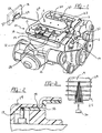
- the subject invention shown in Figure 1 is a wiring assembly 10 for an intake manifold 12 having a flexible circuit assembly 24 sandwiched between layers of foam 14 attached to the intake manifold 12.
- the intake manifold 12 is mounted to an internal combustion engine 16 to provide for regulation of an air fuel mixture.
- a plurality of electrical devices 19 disposed within or near the intake manifold communicate with a controller 18 to control and monitor the engine 16.
- the electrical devices 19 include fuel injectors 20 for regulating the amount of fuel mixed with air drawn through the intake manifold 12 and into the engine 16.
- the electrical devices 19 also include sensors 22 that communicate current engine 16 conditions to the controller 18.
- the sensors 22 may be of any type known in the art including but not limited to a throttle position sensor, a knock sensor, an engine temperature sensor, and an EGR valve. The operational details of these devices are as known in the art and form no part in this invention.
- a connector 32 attaches to each electrical device 19.
- An input connector 30 attached to the flexible circuit assembly 24 provides for communication between the electrical devices 19 and the controller 18.
- the intake manifold 12 in the preferred embodiment is fabricated from plastic and covered with layers of foam 14 to abate noise emanating from the intake manifold 12.
- the layers of foam 14 are secured to the intake manifold 12 by mechanical attachments shown schematically at 15.
- the mechanical attachment 15 may be on any type known to those knowledgeable in the art, including a post and barb style clip, or the layers of foam may be secured by a decorative plastic engine covered attached to the intake manifold 12.
- a flexible circuit assembly 24 is sandwiched between the layers of foam 14 and connected to the plurality of electrical devices 19.
- an alternate embodiment of the subject invention integrates each of the electrical devices 19 into the flexible circuit assembly 24 to form a one-piece flexible circuit/electrical device assembly 34.
- the flexible circuit/electrical device assembly 34 does not require the connectors 32 because each of the electrical devicesare terminated directly to the flexible circuit assembly 24.
- the flexible circuit/electrical device assembly 34 allows for ease of replacement to facilitate repair.
- the flexible circuit/electrical device assembly 34 allows a maintenance technician to replace all electrical devices 19 as one unit instead of consuming an inordinate amount of time isolating and replacing the one disabled electrical device 19.
- the flexible circuit assembly 24 may be fabricated by any method known in the art. Methods of fabricating the circuit assembly 24 include photographic processes and extruding processes. Referring to Figure 3, an embodiment of the subject invention utilizes the photographic process to form the flexible circuit 24 onto one of the layers of foam 14. The integrated flexible circuit and layer of foam 25 would then be sandwiched between other layers of foam 14 and attached to the plurality of electrical devices 19. It should be under stood that any method known in the art may be used to fabricate the circuit assembly.
- another embodiment of the subject invention includes additional separate flexible circuits 36.
- the additional separate flexible circuits 36 may be added to connect and isolate specific types of electrical devices 19.
- a separate flexible circuit 36 is provided for connection to the fuel injectors 20 and a second flexible circuit assembly provides for connection to the sensors 22 disposed within or adjacent to the intake manifold 12.
- Each of the additional flexible circuits 36 may be separated from the other flexible circuits 36 by an additional layer of foam 38.
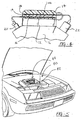
- the layers of foam of the subject invention provide for the abatement of noise emanating from the intake manifold 12, and additionally provide protection of the flexible circuit assembly 24 from the environment present within a motor vehicle engine compartment 40.
- a plastic cover (not shown) may be provided to cover the layers of foam 14 and the intake manifold 12 to provide for an aesthetically pleasing appearance.
- an additional embodiment of the subject invention provides a decorative skin 42 disposed on the layers of foam 14, thereby eliminating the need for the plastic cover.
- a printed design 44 may be printed onto the decorative skin 42.
- a variation of this embodiment would provide for custom printing of a specific customer selected design onto the decorative skin 42. The customer is able to select any design and have that design custom printed onto the decorative skin 42 for assembly to the vehicle.
- the foregoing description is exemplary, and not just a material specification.
Landscapes
- Engineering & Computer Science (AREA)
- Mechanical Engineering (AREA)
- Chemical & Material Sciences (AREA)
- Combustion & Propulsion (AREA)
- General Engineering & Computer Science (AREA)
- Microelectronics & Electronic Packaging (AREA)
- Ceramic Engineering (AREA)
- Fuel-Injection Apparatus (AREA)
- Electrical Control Of Air Or Fuel Supplied To Internal-Combustion Engine (AREA)
- Installation Of Indoor Wiring (AREA)
Abstract
Description
Claims (16)
- A wiring harness assembly for an intake manifold mounted to an internal combustion engine comprising;a plurality of electrical devices;foam disposed on said intake manifold; anda flexible circuit assembly within said foam and connected to said plurality of electrical devices.
- The assembly of claim 1, wherein said flexible circuit assembly includes at least one input connector and a plurality of output connectors for attachment to said plurality of electrical devices.
- The assembly of claim 1, wherein said flexible circuit is sandwiched between layers of foam.
- The assembly of claim 3, wherein said flexible circuit is formed onto one of said layers of foam.
- The assembly of claim 3, further including a plurality of flexible circuits sandwiched between said layers of foam, each of said flexible circuits separated from each of the other flexible circuits by said layers of foam.
- The assembly of claim 3, further including another flexible circuit assembly and a third layer of foam, said third layer of foam separating said flexible circuit assemblies sandwiched between said layers of foam.
- The assembly of claim 1, wherein said flexible circuit assembly and said electrical devices are one integral assembly such that the entire flexible circuit assembly and said electrical devices are replaceable as one unit.
- The assembly of claim 1, wherein said foam is attached to said intake manifold with a plurality of mechanical fasteners.
- The assembly of claim 1, wherein said intake manifold is fabricated from a plastic material.
- The assembly of claim 1, wherein one of said layers of foam includes a decorative skin.
- The assembly of claim 10, wherein said decorative skin further includes a printed design.
- A wiring harness assembly for an intake manifold mounted to an internal combustion engine comprising;at least two layers of foam disposed on said intake manifold;a flexible circuit assembly including a plurality of integral electrical devices;said flexible circuit assembly sandwiched between said layers of foam and said flexible circuit assembly and said electrical devices are replaceable as one unit.
- The assembly of claim 12, wherein said flexible circuit assembly includes an output connector for connection to a controller of the motor vehicle.
- The assembly of claim 12, wherein said plurality of electrical devices includes at least one fuel injector.
- The assembly of claim 12, wherein said plurality of electrical devices includes sensors disposed within said intake manifold.
- The assembly of claim 12, wherein said intake manifold is fabricated from plastic.
Applications Claiming Priority (2)
| Application Number | Priority Date | Filing Date | Title |
|---|---|---|---|
| US16251799P | 1999-10-29 | 1999-10-29 | |
| US162517P | 1999-10-29 |
Publications (3)
| Publication Number | Publication Date |
|---|---|
| EP1096134A2 true EP1096134A2 (en) | 2001-05-02 |
| EP1096134A3 EP1096134A3 (en) | 2002-04-03 |
| EP1096134B1 EP1096134B1 (en) | 2003-07-16 |
Family
ID=22585966
Family Applications (1)
| Application Number | Title | Priority Date | Filing Date |
|---|---|---|---|
| EP00203707A Expired - Lifetime EP1096134B1 (en) | 1999-10-29 | 2000-10-25 | Wiring harness assembly for an intake manifold |
Country Status (3)
| Country | Link |
|---|---|
| US (1) | US6494174B1 (en) |
| EP (1) | EP1096134B1 (en) |
| DE (1) | DE60003880T2 (en) |
Cited By (2)
| Publication number | Priority date | Publication date | Assignee | Title |
|---|---|---|---|---|
| US6494174B1 (en) * | 1999-10-29 | 2002-12-17 | Siemens Vdo Automotive Inc. | Wiring harness assembly for an intake manifold |
| CN101187335B (en) * | 2006-11-21 | 2012-08-01 | 迪尔公司 | Conduit enclosure system for enclosing an engine wiring harness |
Families Citing this family (9)
| Publication number | Priority date | Publication date | Assignee | Title |
|---|---|---|---|---|
| JP2004505208A (en) * | 2000-07-27 | 2004-02-19 | ビステオン グローバル テクノロジーズ インコーポレイテッド | Integrated powertrain control system for large engines |
| JP2002303151A (en) * | 2001-04-05 | 2002-10-18 | Calsonic Kansei Corp | Engine control unit |
| US6688290B2 (en) * | 2002-01-31 | 2004-02-10 | Visteon Global Technologies, Inc. | Integrated fuel delivery and electronic powertrain control module and method of manufacture |
| US20040211582A1 (en) * | 2003-04-23 | 2004-10-28 | Siemens Vdo Automotive, Inc. | Vehicle component having an electrical conductor adhesively secured into the component |
| DE10334913B4 (en) * | 2002-08-07 | 2014-03-13 | Siemens Vdo Automotive Inc. | Intake manifold with integrated features |
| WO2004106053A1 (en) * | 2003-05-29 | 2004-12-09 | E. I. Du Pont De Nemours And Company | Air intake manifolds and other structures of rigid and foamed polymeric materials having reduced noise transmission and processes for their preparation |
| US7341038B1 (en) | 2006-12-15 | 2008-03-11 | Federal - Mogul World Wide, Inc. | Engine cover with embedded leads |
| US9753073B2 (en) | 2015-11-23 | 2017-09-05 | General Electric Company | Method and systems for testing an electrical circuit |
| US11933256B1 (en) * | 2022-10-13 | 2024-03-19 | GM Global Technology Operations LLC | Intake manifold cover configured for fluid distribution and capture of insulator |
Family Cites Families (28)
| Publication number | Priority date | Publication date | Assignee | Title |
|---|---|---|---|---|
| US2509093A (en) | 1950-05-23 | Unified distribution of fluid and electrical ignition | ||
| US2488096A (en) | 1947-03-21 | 1949-11-15 | William R Newman | One-piece plastic ignition harness for gasoline engines |
| US4776313A (en) | 1987-06-01 | 1988-10-11 | Ford Motor Company | Compact integrated engine induction air/fuel system |
| US4805564A (en) | 1987-09-22 | 1989-02-21 | Sharon Manufacturing Company | Engine intake manifold assembly |
| US5003933A (en) | 1989-11-06 | 1991-04-02 | General Motors Corporation | Integrated induction system |
| US5211149A (en) | 1990-06-29 | 1993-05-18 | Siemens Automotive L.P. | Fuel rail for bottom and side fed injectors |
| US5163406A (en) | 1990-08-07 | 1992-11-17 | Siemens Automotive L.P. | Intake manifold/fuel rail |
| US5189782A (en) | 1990-12-20 | 1993-03-02 | Ford Motor Company | Method of making integrally formed and tuned fuel rail/injectors |
| DE4206370A1 (en) | 1991-05-17 | 1992-11-19 | Mann & Hummel Filter | CONTROL STRIP IN COMPACT PLASTIC DESIGN |
| DE4118512A1 (en) | 1991-06-06 | 1992-12-10 | Bosch Gmbh Robert | ELECTRICALLY OPERABLE FUEL INJECTION VALVE AND METHOD FOR THEIR ELECTRICAL CONTACT |
| DE4131537A1 (en) | 1991-09-21 | 1993-04-01 | Bosch Gmbh Robert | FUEL DISTRIBUTOR |
| JPH05114310A (en) | 1991-10-24 | 1993-05-07 | Yazaki Corp | Flat wire harness and its manufacture |
| JP2700115B2 (en) * | 1992-02-26 | 1998-01-19 | 矢崎総業株式会社 | Electrical wiring method for engine mounting parts |
| JP3148831B2 (en) | 1992-05-01 | 2001-03-26 | 本田技研工業株式会社 | High pressure cord cover for internal combustion engine |
| FR2697293B1 (en) | 1992-10-26 | 1994-11-10 | Solex | Feeding device with integrated tubing. |
| US5218936A (en) | 1992-11-13 | 1993-06-15 | Ford Motor Company | Ignition system including spark distribution cassette and ignition coil |
| US5353767A (en) | 1993-12-17 | 1994-10-11 | General Motors Corporation | Fuel and air induction system |
| US5447140A (en) | 1993-12-20 | 1995-09-05 | General Motors Corporation | Fuel injection |
| JPH07293269A (en) * | 1994-04-28 | 1995-11-07 | Hitachi Ltd | Electric circuit device of automobile |
| US5598824A (en) | 1996-04-15 | 1997-02-04 | Ford Motor Company | Fuel delivery system for an internal combustion engine |
| JPH09317556A (en) * | 1996-05-23 | 1997-12-09 | Toyota Motor Corp | Cylinder head cover |
| US5743235A (en) * | 1996-11-22 | 1998-04-28 | Lueder; Lawrence Arimidio | Molded-in wiring for intake manifolds |
| JP3092535B2 (en) * | 1996-12-18 | 2000-09-25 | トヨタ車体株式会社 | Engine wire harness assembly structure |
| JPH10274111A (en) * | 1997-03-28 | 1998-10-13 | Denso Corp | Intake device and method of assembling the same |
| DE29706751U1 (en) | 1997-04-15 | 1997-06-12 | FER Fahrzeugelektrik GmbH, 99817 Eisenach | Headlining for an interior of a motor vehicle |
| DE19842041A1 (en) | 1997-09-16 | 1999-03-25 | Whitaker Corp | Cabling set |
| US6186106B1 (en) * | 1997-12-29 | 2001-02-13 | Visteon Global Technologies, Inc. | Apparatus for routing electrical signals in an engine |
| US6494174B1 (en) * | 1999-10-29 | 2002-12-17 | Siemens Vdo Automotive Inc. | Wiring harness assembly for an intake manifold |
-
2000
- 2000-10-24 US US09/695,478 patent/US6494174B1/en not_active Expired - Lifetime
- 2000-10-25 DE DE60003880T patent/DE60003880T2/en not_active Expired - Lifetime
- 2000-10-25 EP EP00203707A patent/EP1096134B1/en not_active Expired - Lifetime
Cited By (2)
| Publication number | Priority date | Publication date | Assignee | Title |
|---|---|---|---|---|
| US6494174B1 (en) * | 1999-10-29 | 2002-12-17 | Siemens Vdo Automotive Inc. | Wiring harness assembly for an intake manifold |
| CN101187335B (en) * | 2006-11-21 | 2012-08-01 | 迪尔公司 | Conduit enclosure system for enclosing an engine wiring harness |
Also Published As
| Publication number | Publication date |
|---|---|
| EP1096134B1 (en) | 2003-07-16 |
| DE60003880D1 (en) | 2003-08-21 |
| DE60003880T2 (en) | 2004-06-03 |
| EP1096134A3 (en) | 2002-04-03 |
| US6494174B1 (en) | 2002-12-17 |
Similar Documents
| Publication | Publication Date | Title |
|---|---|---|
| US6494174B1 (en) | Wiring harness assembly for an intake manifold | |
| US6167855B1 (en) | Integrated air-fuel module and assembly method | |
| US6577025B2 (en) | Electrical wiring system for the drive unit in vehicles | |
| DE69311498T2 (en) | Feeder with an integrated manifold | |
| US6988670B2 (en) | Heating/ventilating/air conditioning systems for vehicles | |
| JP3872814B2 (en) | Circuit device for functional module that can be installed in an automobile | |
| RU2140555C1 (en) | Control device for internal combustion engine | |
| WO1999010751A1 (en) | Fuel injection diagnostic control device | |
| US6357414B1 (en) | Air manifold mounting for engine control circuitry | |
| US6408811B1 (en) | Vehicle engine components providing integral interconnect circuitry system | |
| US6502547B2 (en) | Foamed over integrated circuit for intake manifold | |
| US6513479B2 (en) | Harness structure of engine relative parts | |
| EP0857618B1 (en) | Engine having offset cylinder banks | |
| DE19843771A1 (en) | Electromotive actuator, in particular with a throttle valve | |
| US6712052B2 (en) | Engine control unit | |
| JPH1144265A (en) | Intake system control device for internal combustion engine | |
| JPH0466736A (en) | Internal combustion engine control system | |
| US20020132499A1 (en) | Electrical connection structure in a motor vehicle | |
| KR100482490B1 (en) | Air quality control sensor having temperature sensor for outside door as a one body | |
| US7363900B2 (en) | Multi-cylinder internal combustion engine for vehicles | |
| US20040211582A1 (en) | Vehicle component having an electrical conductor adhesively secured into the component | |
| US20020173182A1 (en) | Molded connector assembly for making electronically conductive connections with components in a vehicle engine compartment | |
| EP1356997B1 (en) | Vehicle component having an electrical conductor adhesively secured into the component | |
| JP2001323851A (en) | Harness structure of engine related parts | |
| JP2002188551A (en) | Wiring assembly method for ignition coil device |
Legal Events
| Date | Code | Title | Description |
|---|---|---|---|
| PUAI | Public reference made under article 153(3) epc to a published international application that has entered the european phase |
Free format text: ORIGINAL CODE: 0009012 |
|
| AK | Designated contracting states |
Kind code of ref document: A2 Designated state(s): DE FR GB Kind code of ref document: A2 Designated state(s): AT BE CH CY DE DK ES FI FR GB GR IE IT LI LU MC NL PT SE |
|
| AX | Request for extension of the european patent |
Free format text: AL;LT;LV;MK;RO;SI |
|
| PUAL | Search report despatched |
Free format text: ORIGINAL CODE: 0009013 |
|
| AK | Designated contracting states |
Kind code of ref document: A3 Designated state(s): AT BE CH CY DE DK ES FI FR GB GR IE IT LI LU MC NL PT SE |
|
| AX | Request for extension of the european patent |
Free format text: AL;LT;LV;MK;RO;SI |
|
| RIC1 | Information provided on ipc code assigned before grant |
Free format text: 7F 02M 35/104 A, 7B 60R 16/02 B |
|
| 17P | Request for examination filed |
Effective date: 20021002 |
|
| AKX | Designation fees paid |
Free format text: DE FR GB |
|
| 17Q | First examination report despatched |
Effective date: 20021121 |
|
| GRAH | Despatch of communication of intention to grant a patent |
Free format text: ORIGINAL CODE: EPIDOS IGRA |
|
| GRAH | Despatch of communication of intention to grant a patent |
Free format text: ORIGINAL CODE: EPIDOS IGRA |
|
| GRAA | (expected) grant |
Free format text: ORIGINAL CODE: 0009210 |
|
| AK | Designated contracting states |
Designated state(s): DE FR GB |
|
| PG25 | Lapsed in a contracting state [announced via postgrant information from national office to epo] |
Ref country code: FR Free format text: LAPSE BECAUSE OF FAILURE TO SUBMIT A TRANSLATION OF THE DESCRIPTION OR TO PAY THE FEE WITHIN THE PRESCRIBED TIME-LIMIT Effective date: 20030716 |
|
| REG | Reference to a national code |
Ref country code: GB Ref legal event code: FG4D |
|
| REG | Reference to a national code |
Ref country code: IE Ref legal event code: FG4D |
|
| REF | Corresponds to: |
Ref document number: 60003880 Country of ref document: DE Date of ref document: 20030821 Kind code of ref document: P |
|
| PLBE | No opposition filed within time limit |
Free format text: ORIGINAL CODE: 0009261 |
|
| STAA | Information on the status of an ep patent application or granted ep patent |
Free format text: STATUS: NO OPPOSITION FILED WITHIN TIME LIMIT |
|
| 26N | No opposition filed |
Effective date: 20040419 |
|
| REG | Reference to a national code |
Ref country code: IE Ref legal event code: MM4A |
|
| EN | Fr: translation not filed | ||
| REG | Reference to a national code |
Ref country code: DE Ref legal event code: R084 Ref document number: 60003880 Country of ref document: DE |
|
| PGFP | Annual fee paid to national office [announced via postgrant information from national office to epo] |
Ref country code: GB Payment date: 20181031 Year of fee payment: 19 |
|
| PGFP | Annual fee paid to national office [announced via postgrant information from national office to epo] |
Ref country code: DE Payment date: 20181228 Year of fee payment: 19 |
|
| REG | Reference to a national code |
Ref country code: DE Ref legal event code: R119 Ref document number: 60003880 Country of ref document: DE |
|
| PG25 | Lapsed in a contracting state [announced via postgrant information from national office to epo] |
Ref country code: DE Free format text: LAPSE BECAUSE OF NON-PAYMENT OF DUE FEES Effective date: 20200501 |
|
| GBPC | Gb: european patent ceased through non-payment of renewal fee |
Effective date: 20191025 |
|
| PG25 | Lapsed in a contracting state [announced via postgrant information from national office to epo] |
Ref country code: GB Free format text: LAPSE BECAUSE OF NON-PAYMENT OF DUE FEES Effective date: 20191025 |