EP1095887A2 - Sheet conveying apparatus and image torming apparatus provided therewith - Google Patents
Sheet conveying apparatus and image torming apparatus provided therewith Download PDFInfo
- Publication number
- EP1095887A2 EP1095887A2 EP00123656A EP00123656A EP1095887A2 EP 1095887 A2 EP1095887 A2 EP 1095887A2 EP 00123656 A EP00123656 A EP 00123656A EP 00123656 A EP00123656 A EP 00123656A EP 1095887 A2 EP1095887 A2 EP 1095887A2
- Authority
- EP
- European Patent Office
- Prior art keywords
- sheet conveying
- sheets
- driving means
- conveying apparatus
- sheet
- Prior art date
- Legal status (The legal status is an assumption and is not a legal conclusion. Google has not performed a legal analysis and makes no representation as to the accuracy of the status listed.)
- Granted
Links
Images





Classifications
-
- G—PHYSICS
- G03—PHOTOGRAPHY; CINEMATOGRAPHY; ANALOGOUS TECHNIQUES USING WAVES OTHER THAN OPTICAL WAVES; ELECTROGRAPHY; HOLOGRAPHY
- G03G—ELECTROGRAPHY; ELECTROPHOTOGRAPHY; MAGNETOGRAPHY
- G03G15/00—Apparatus for electrographic processes using a charge pattern
- G03G15/65—Apparatus which relate to the handling of copy material
- G03G15/6552—Means for discharging uncollated sheet copy material, e.g. discharging rollers, exit trays
-
- B—PERFORMING OPERATIONS; TRANSPORTING
- B65—CONVEYING; PACKING; STORING; HANDLING THIN OR FILAMENTARY MATERIAL
- B65H—HANDLING THIN OR FILAMENTARY MATERIAL, e.g. SHEETS, WEBS, CABLES
- B65H29/00—Delivering or advancing articles from machines; Advancing articles to or into piles
- B65H29/20—Delivering or advancing articles from machines; Advancing articles to or into piles by contact with rotating friction members, e.g. rollers, brushes, or cylinders
-
- B—PERFORMING OPERATIONS; TRANSPORTING
- B65—CONVEYING; PACKING; STORING; HANDLING THIN OR FILAMENTARY MATERIAL
- B65H—HANDLING THIN OR FILAMENTARY MATERIAL, e.g. SHEETS, WEBS, CABLES
- B65H29/00—Delivering or advancing articles from machines; Advancing articles to or into piles
- B65H29/58—Article switches or diverters
- B65H29/60—Article switches or diverters diverting the stream into alternative paths
-
- B—PERFORMING OPERATIONS; TRANSPORTING
- B65—CONVEYING; PACKING; STORING; HANDLING THIN OR FILAMENTARY MATERIAL
- B65H—HANDLING THIN OR FILAMENTARY MATERIAL, e.g. SHEETS, WEBS, CABLES
- B65H2301/00—Handling processes for sheets or webs
- B65H2301/10—Selective handling processes
- B65H2301/16—Selective handling processes of discharge in bins, stacking, collating or gathering
-
- B—PERFORMING OPERATIONS; TRANSPORTING
- B65—CONVEYING; PACKING; STORING; HANDLING THIN OR FILAMENTARY MATERIAL
- B65H—HANDLING THIN OR FILAMENTARY MATERIAL, e.g. SHEETS, WEBS, CABLES
- B65H2301/00—Handling processes for sheets or webs
- B65H2301/30—Orientation, displacement, position of the handled material
- B65H2301/33—Modifying, selecting, changing orientation
- B65H2301/333—Inverting
- B65H2301/3331—Involving forward reverse transporting means
- B65H2301/33312—Involving forward reverse transporting means forward reverse rollers pairs
-
- B—PERFORMING OPERATIONS; TRANSPORTING
- B65—CONVEYING; PACKING; STORING; HANDLING THIN OR FILAMENTARY MATERIAL
- B65H—HANDLING THIN OR FILAMENTARY MATERIAL, e.g. SHEETS, WEBS, CABLES
- B65H2402/00—Constructional details of the handling apparatus
- B65H2402/10—Modular constructions, e.g. using preformed elements or profiles
-
- B—PERFORMING OPERATIONS; TRANSPORTING
- B65—CONVEYING; PACKING; STORING; HANDLING THIN OR FILAMENTARY MATERIAL
- B65H—HANDLING THIN OR FILAMENTARY MATERIAL, e.g. SHEETS, WEBS, CABLES
- B65H2403/00—Power transmission; Driving means
- B65H2403/90—Machine drive
- B65H2403/94—Other features of machine drive
- B65H2403/942—Bidirectional powered handling device
-
- G—PHYSICS
- G03—PHOTOGRAPHY; CINEMATOGRAPHY; ANALOGOUS TECHNIQUES USING WAVES OTHER THAN OPTICAL WAVES; ELECTROGRAPHY; HOLOGRAPHY
- G03G—ELECTROGRAPHY; ELECTROPHOTOGRAPHY; MAGNETOGRAPHY
- G03G2215/00—Apparatus for electrophotographic processes
- G03G2215/00362—Apparatus for electrophotographic processes relating to the copy medium handling
- G03G2215/00919—Special copy medium handling apparatus
- G03G2215/00945—Copy material feeding speed varied over the feed path
-
- Y—GENERAL TAGGING OF NEW TECHNOLOGICAL DEVELOPMENTS; GENERAL TAGGING OF CROSS-SECTIONAL TECHNOLOGIES SPANNING OVER SEVERAL SECTIONS OF THE IPC; TECHNICAL SUBJECTS COVERED BY FORMER USPC CROSS-REFERENCE ART COLLECTIONS [XRACs] AND DIGESTS
- Y10—TECHNICAL SUBJECTS COVERED BY FORMER USPC
- Y10S—TECHNICAL SUBJECTS COVERED BY FORMER USPC CROSS-REFERENCE ART COLLECTIONS [XRACs] AND DIGESTS
- Y10S271/00—Sheet feeding or delivering
- Y10S271/902—Reverse direction of sheet movement
Definitions
- the present invention relates to a sheet conveying apparatus with which simplification of apparatus expansion operations and reduction of the apparatus costs can be realized and to an image forming apparatus provided therewith.
- a sheet discharge portion including sheet discharge rollers 300 is formed as a unit and a sheet discharge roller unit 200 is replaced with a predetermined unit (for example, an option unit 400 shown in FIG. 12B) at the time of performing a desired processing such as double side conveyance and face-up sheet discharge, thereby the mechanism of the printer body can be simplified.
- a small-size printing apparatus body can be configured only by providing means for image formation and for sheet feeding; accordingly, for the uses requiring a basic mechanism alone, a costless apparatus without any extra equipment can be provided.
- the sheet discharge roller pair 300 existing in the sheet discharge roller unit 200 are to be replaced together.
- the sheet discharge roller pair 300 itself is necessary for the option unit 400 and their function to convey sheets is the same even in the sheet discharge roller unit 200.
- the present invention is to provide an image forming apparatus which is configured in such a manner that, when its system needs to be altered, the functions needed to be altered alone can be added to/replaced with the original ones, thereby the cost of altering the system can be held down and the alteration of the same can be simplified.
- the configuration includes a rotor to which torque in the fixed direction is transmitted and transmitting means for transmitting torque to the rotor, and the transmitting means is replaceable with second driving means capable of freely rotating the rotor in both the forward and the backward directions.
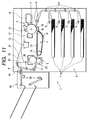
- a printer as an image forming apparatus can be altered into two forms: a plain model printer comprising only an image forming apparatus 1; and an option model printer having a processing apparatus 46 (refer to FIG. 11) capable of performing processing such as stapling and punching, a double side unit for reversing a sheet so as to form images on both sides of the sheet, etc. fitted to its frame body.
- a processing apparatus 46 (refer to FIG. 11) capable of performing processing such as stapling and punching, a double side unit for reversing a sheet so as to form images on both sides of the sheet, etc. fitted to its frame body.
- this printer adopts an electrographic method as an image forming method in which toner images are transferred on sheets
- the present invention is not intended to be limited to this method, but applicable to an ink jet recording method in which images are formed by discharging ink, a thermal printing method, etc.
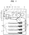
- an image forming apparatus body 1 arranged are a sheet feeding portion 2 for loading/storing sheets on which images are formed and for feeding the sheets to an image forming portion 3 one by one, the image forming portion 3 for forming images on each of the sheets, a sheet conveying portion 4 for conveying sheets on which images have been transferred, an image fixing portion 5 for fixing the images on the sheets almost indefinitely, a sheet discharge portion 6 for discharging the sheet on which images are fixed out of the apparatus, and a processing apparatus 46 for performing a certain processing on the image formed sheets.
- a sheet feeding portion 2 for loading/storing sheets on which images are formed and for feeding the sheets to an image forming portion 3 one by one
- the image forming portion 3 for forming images on each of the sheets
- a sheet conveying portion 4 for conveying sheets on which images have been transferred
- an image fixing portion 5 for fixing the images on the sheets almost indefinitely
- a sheet discharge portion 6 for discharging the sheet on which images are fixed out of the apparatus
- a processing apparatus 46 for performing a
- Sheet cassettes 7 for storing sheets P on which images are to be formed are arranged on the bottom side of the apparatus body 1.
- the sheets P are sent out from the sheet cassettes 7 by pickup rollers 8.
- one sheet is separated from the sheets P having been sent out by separation means (for example, separation claws, separation pads and reversing rollers) not shown in the drawing.
- the separated sheet P is forced into a resist roller pair 10 provided near the entrance to the image forming portion 3 by means of sheet conveying roller pairs 9.
- Resist roller pair 10 fixes the position of the conveyed sheet P and conveys the same in such a manner that the conveyance is well timed in terms of the image forming operation.
- the image forming portion utilizing the electrographic method is provided with a laser scanner 13 for laser light irradiation on the basis of image data inputted to the apparatus, a photographic drum 11 as an image carrier, a primary electrically charging equipment 12 for uniformly charging the surface of the photographic drum 11, a developing equipment 14 for allowing an electrostatic latent image formed on the photographic drum 11 to be visible by sticking a toner thereon, a transfer charging equipment 15 for transferring the toner image formed on the photographic drum 11 to a sheet P, a separation charging equipment 16 for separating the sheet P have been subjected to the toner image transfer from the photographic drum 11 and cleaning equipment 17 for cleaning the drum 11 by removing the toner remaining thereon for the subsequent image formation.
- the sheet conveying portion 4 located downstream in the sheet-conveying direction of the image forming portion 3 is provided with a conveying belt 19 engaging conveying rollers 18.
- This belt 19 is configured in such a manner that it can convey the sheet P while preserving the toner image transferred thereto.
- the toner image having been transferred to the sheet P is fixed thereon almost indefinitely in such a manner as to hold the sheet P between an image fixing roller pair 20 which has been heated with a heater (not shown in the drawing) and applying heat and pressure thereto so as to melt the toner.
- the sheet P having been subjected to image fixing is sent to the sheet discharge portion 6.
- the sheet P having passed between the image fixing roller pair 20 is conveyed by conveying roller pairs 21 (21a, 21b) and 22 (22a, 22b) through a conveying path 36 and discharged by a sheet discharge roller pair 23 (23a, 23b) into a sheet discharge tray 37 formed on an upper surface of the apparatus body 1.
- the apparatus of the plain model is provided with neither processing apparatus for performing processing on the sheet P nor double side unit for forming images on both sides of the sheet; therefore, the discharge roller pair 23 is allowed to always rotate in the direction as to discharge sheets into the sheet discharge tray 37.
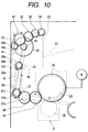
- the motor M drives the image fixing roller 20.
- a gear 24, as transmitting means, and the image fixing roller 20 are provided coaxially.
- the other transmitting means: a gear 25 meshing with the gear 24, a gear 26, and a gear 27a are arranged in series in sequence.
- the gear 27a and the conveyance roller 21b are coaxially arranged, and the rotation of the gear 27a allows the conveyance roller 21b to rotate in such a direction as to convey sheets to the sheet discharge tray 37.
- the gear 27a and a pulley 27b are provided coaxially.
- the other pulley 28b and the conveying roller 22b are provided coaxially, and the pulleys 27b and 28b are connected with a timing belt 35.
- the rotation of the conveying roller 21b allows the conveying roller 22b to rotate at the same timing and in the same direction.
- the pulley 28b and the gear 28a are provided coaxially, and the gear 28a transmits the rotation of the pulley 28b to a gear 29 with which the gear 28a meshes.
- a gear 30 meshes, and a gear 31, gear 32, gear 33 and gear 34 mesh with each other in sequence, so as to constitute a gear bank.
- a gear 34 and the sheet discharge roller 23b are provided coaxially.
- the discharge roller pair 23 is configured in such a manner as to be allowed to rotate in a direction that conveys sheets to the sheet discharge tray 37.
- the sheet discharge portion 6 is configured in such a manner that a sheet conveying path 36 can be opened by allowing the side portion of the image forming apparatus to pivot, as shown in FIG. 3. This makes easier the maintenance of the conveying path 36 jammed with sheets as well as of each roller.
- FIG. 4 is a view of the image forming apparatus body 1 in a state where a pivot guide portion 36a, which allows the conveying path 36 to be opened, is allowed to pivot on the point 36c, as seen from the direction denoted by an arrow A in FIG. 3.
- Reference numeral 38 denotes a gear unit.
- the gear unit is also shown in FIG. 5.
- the gear unit is a zigzag member which is formed of the material having a relatively high strength, such as metal sheet, and has the gears 29, 30 and 31 of the above-described gear bank pivotably fitted thereto.
- the gear unit 38 is fixed with screws 39 to the conveying path 36 at the location through which sheets do not pass in state that it meshes with the gears 28a and 32 of the gear bank.
- the gear unit 38 is previously fitted thereto and the gear unit 38 configures its transmitting means.
- One sheet is separated by the separation means not shown in the drawings from the sheets P sent out from the sheet cassettes 7 by the pickup rollers 8, then it is conveyed toward the image forming portion 3 by the conveying roller pairs 9.
- the resist roller pair 10 fixes the position of the conveyed sheet P and stops the conveyance of the sheet P temporarily so that the conveyance will be well timed in terms of the image forming operation of the image forming portion 3.
- the sheet P having been subjected to correction of skew feed and timing in terms of the image forming operation of the image forming portion 3 by the resist roller pair 10 is then conveyed to the image forming portion 3 by the rotational motion of the resist roller pair 10.
- the image forming operation is started at the image forming portion 3.
- the surface of the photographic drum 11 is charged uniformly with the primary charging equipment 12.
- image data are written by the laser light irradiation of the laser scanner 13.
- an electrostatic latent image is formed on the photographic drum 11.
- the developing equipment 14 sticks a toner on the photographic drum 11 having an electrostatic latent image formed thereon, thereby a toner image to be transferred to a sheet is formed on the surface of the photographic drum 11.
- the toner image having been formed on the photographic drum 11 is transferred to the sheet P which has been conveyed from the resist roller pair 10 and timed to synchronize with the image forming operation by the transfer charging equipment 15. And the operation for separating the sheet P and the photographic drum 11 is performed by the separation charging equipment 16 provided immediately behind the transfer charging equipment 15 downstream in the sheet conveying direction. The excess toner remaining on the surface of the photographic drum 11 is removed with the cleaning equipment 17 so as to allow the photographic drum 11 to provide for the subsequent image forming operation.
- the sheet P separated from the photographic drum 11 by the separation charging equipment 16 of the image forming portion 3 is conveyed to the image fixing portion 5 by the conveying portion 4 provided downstream in the sheet conveying direction.
- the toner image having been transferred to the sheet P is melted by the heat and pressure applied to the sheet P by the image fixing roller pair 20 provided to the image fixing portion 5 and fixed on the sheet P almost indefinitely.
- the sheets P having the toner fixed thereon are conveyed through the conveying path 36 by the conveying roller pairs 21 and 22 and discharged into and stacked in the sheet discharge tray 37 with the side on which an image has been formed facing down by the sheet discharge roller pair 23. Since the sheets P are stacked with the side on which an image has been formed facing down, in the multiple page image formation with this printer, the image forming operation is started with the first page so that the sheets are not arranged in the wrong page order.
- the image forming operation of this image forming apparatus is as described above.
- a processing apparatus 46 as an option to be added to a printer, is a stapling apparatus which ties sheets in bundles and performs stapling processing on the bundles (refer to FIG. 11). Since the configuration of a stapling apparatus is a well-known art, its description will be omitted.
- the present invention is described in terms of its preferred embodiment, it is not intended to be limited to the specific processing type of processing apparatus, but applicable to any type of processing apparatus such as sorting apparatus for sorting sheets into bundles, stamping apparatus for stamping sheets, and punching apparatus for punching a hole in sheets (punching processing). Further, if the sheets having been subjected to processing in the processing apparatus 46 are conveyed again to the image forming apparatus 1, the processing apparatus 46 is allowed to be a double side unit for forming images on both sides of the sheets.
- the sheet discharge roller pair 23 needs to be configured in such a manner as to be allowed to rotate in both the forward and the backward directions.
- the rotational driving of each roller pair is performed by the transmitting means arranged in series from the image fixing portion 5; accordingly, in order to rotate the sheet discharge roller pair 23 in the direction opposite to the sheet discharge direction, the motor M which drives the image fixing portion 5 needs to be rotated in the reverse order.
- the image fixing roller pair 20 taking into account its special configuration, wear, etc., it is not realistic to rotate it in the direction opposite to the sheet conveying direction. Even if the image fixing roller pair is rotated in the reverse direction, the image fixing operation cannot be performed on the sheet during its rotation in the reverse direction, which may result in decrease in throughput.
- the printer is configured in such a manner that part of the gear bank of the plain model printer is formed as a unit as describe above and the gear unit 38 is replaced with a motor unit 40 as second driving means.
- This configuration does not require any large-scale unit replacement which the prior art have done and enables the expansion of printer regardless of its simplicity.
- the configuration of the unit 40 and the method of expanding the printer will be described below.
- the gear unit 38 is a unit comprising part of the gear bank configured in series from the motor M toward the sheet discharge roller pair 23.
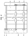
- the motor unit 40 is almost the same as the gear unit 38 in size and shape and has a motor M' capable of rotating in both the forward and the backward directions, as shown in FIG. 7. It also has gears 41 and 42 which are rotated by the drive of the motor M'.
- the motor unit 40 is located at the portion from which the gear unit 38 has been removed in such a manner that its gear 42 meshes the gear 32 of the gear bank formed in the printer body 1 and it is fitted to the printer body 1 by fixing means such as screw 39, as shown in FIGS. 6 and 8.
- both the motor unit 40 and the gear unit 38 require the accuracy of gearing; accordingly, each unit is configured in such a manner that it can be easily located upward and downward with slotted holes 38a.
- a sheet conveying path is needed which connects the printer body 1 and the processing apparatus 46.
- the apparatus of the present invention is configured in such a manner that part of its pivot guide 36a can be replaced with a path unit 44 at the time of altering it from the plain model printer to the option model one (refer to FIG. 9).
- the path unit 44 forms a second conveying path 44a for conveying the sheets P having been conveyed in the reverse direction by the sheet discharge roller pair 23 to the processing apparatus 46, when it is fitted to the printer body 1 at the unit fitting position 36b of the pivot guide 36a.
- the path unit 44 has a second sheet discharge roller pair 45 (45a, 45b) which are allowed to rotate when the gear 42 provided in the motor unit 40 meshes the gear 43 provided coaxially with the sheet discharge roller pair 45b.
- the gears 43 and 42 are configured in such a manner as to mesh with each other when the pivot guide 36a is closed.
- the second sheet discharge roller pair 45 is also allowed to rotate in the same direction.
- the conveying path 36 can be exposed at the time of allowing the pivot guide 36a to pivot, as shown in FIG. 3.
- the gear unit 38 is removed from the printer body 1 and the motor unit 40 is fitted thereto.
- the drive of the motor M' of the motor unit 40 is controlled by controlling means not shown in the drawings and its ON/OFF and forward/backward rotation are freely performed according to the directions from the controlling means.
- the rotation of the sheet discharge roller pair 23 can be operated appropriately and freely in such a direction as to discharge sheets to the sheet discharge tray 37 and in the direction opposite thereto independent of the driving of the motor M.
- the path unit 44 is fitted to the printer body at the unit fitting position 36b of the pivot guide 36a.
- the printer is configured in such a manner that the path unit 44 can be easily fitted thereto if only it is fitted to the unit fitting position.
- the pivot guide 36a is closed and the processing apparatus 46 is fitted to a predetermined position at which it can receive sheets P from the second sheet discharge roller pair 45.
- the option model printer can be thus configured.
- the expansion of a printer is performed while allowing the configuration of the printer to be simple, as compared with the prior art method in which the plain model printer is expanded to an option model one by replacing its sheet discharge unit including sheet discharge roller pair with a predetermined unit. This enables the reduction in apparatus costs and provides a simpler method of expanding a printer.
- the sheet P having passed through the image fixing portion 5 is conveyed toward the sheet discharge roller pair 23 by the conveying roller pairs 21 and 22. At this time, the sheet discharge roller pair is being rotated by the drive of the motor M' in such a direction as to discharge the sheet P into the sheet discharge tray 37.
- the sheet P starts to be discharged into the sheet discharge tray 37 while it is held between the sheet discharge roller pair 23.
- the motor M' is allowed to stop its rotational motion (forward rotation) by the control of the controlling means not shown in the drawing and starts to rotate in such a direction as to put the sheet P back into the printing apparatus (backward rotation).
- the proximal end of the sheet (the end portion remaining in the printing apparatus) is introduced into the second conveying path 44a by the action of a flapper (not shown in the drawing) which is provided at the portion where the conveying path 36 and the second conveying path 44a are joined alters the conveying direction of the sheet P.
- the flapper is provided in the path unit 44 and configured in such a manner that it is displaced according to the changes in direction in which the motor M' is rotated.
- the sheet P introduced into the second conveying path 44a is held between the second sheet discharge roller pair 45 and conveyed into the processing apparatus 46 fitted to the printer.
- the motor M' stops driving and enters in a stand-by state for the subsequent operation.
- the sheet P having images formed thereon is conveyed into the processing apparatus 46 in order of page number, subjected to a predetermined processing (stapling processing in this embodiment), and discharged into the tray provided in the processing apparatus 46.
- the motor M' for use in the motor unit 40 of the present invention is a stepping motor of which rotational direction and rotational speed can be freely controlled according to the input of pulse signals.
- the path unit and the motor unit are independently provided and the expansion to the option model printer is performed by the replacement of each unit, however, when these unit are configured and provided as an integral unit so as to expand the plain model printer to the option model one, the object of the present invention can be attained.
- the conveying path may be previously provided in the image forming apparatus body 1 not as a unit.
- the image forming apparatus body is configured in such a manner that it side portion is allowed to pivot, and the unit replacement is performed while allowing the side portion to pivot; however, the present invention is not intended to be limited to this configuration, but applicable to the configuration in which unit replacement can be performed from the front side of the apparatus.
- the plain model image forming apparatus can be altered into the option model image forming apparatus having the processing apparatus fitted thereto by replacing part of the first driving means for driving the first sheet discharge roller pair with the second driving means and by replacing part of the openable and removable portion of the first sheet discharge path with the connecting discharge means.
- the plain model printer needs not to be equipped with the second sheet discharge path and the second sheet discharge roller pair, which can realize the cost reduction and space saving in the plain model printer.
- the configuration includes a rotor to which torque in a fixed direction is transmitted and transmitting unit for transmitting torque to the rotor, and the transmitting unit is replaceable by second driving unit capable of freely rotating the rotor in both forward and backward directions.
Landscapes
- Engineering & Computer Science (AREA)
- Mechanical Engineering (AREA)
- Physics & Mathematics (AREA)
- General Physics & Mathematics (AREA)
- Delivering By Means Of Belts And Rollers (AREA)
- Separation, Sorting, Adjustment, Or Bending Of Sheets To Be Conveyed (AREA)
- Sheets, Magazines, And Separation Thereof (AREA)
Abstract
Description
Claims (16)
- A sheet conveying apparatus, comprising:a rotor to which torque in a direction is transmitted; andtransmitting means for transmitting the torque to the rotor,
wherein the transmitting means is replaceable by driving means capable of freely rotating the rotor in both forward and backward directions. - The sheet conveying apparatus according to claim 1, wherein each of the driving means and the transmitting means comprises an integrally formed unit and is removably attached to the sheet conveying apparatus.
- The sheet conveying apparatus according to claim 1, wherein the rotor is a discharge roller for discharging sheets out from the apparatus and the driving means replaceable by the transmitting means is capable of rotating the discharge roller in such a direction as to discharge the sheets out from the apparatus as well as in the direction opposite to the direction to which the sheets are discharged.
- The sheet conveying apparatus according to claim 1, wherein the replacement of the transmitting means by the driving means is made possible by opening an exterior of the sheet conveying apparatus.
- An image forming apparatus comprising image forming means for forming images on the sheets conveyed by the sheet conveying apparatus according to any one of claims 1 to 4.
- A sheet conveying apparatus, comprising:a rotor for conveying sheets;first driving means for generating torque which allows the rotor to rotate in a fixed direction; andtransmitting means for transmitting a torque generated by the first driving means to the rotor,
wherein the transmitting means is replaceable by a second driving means capable of rotating the rotor. - The sheet conveying apparatus according to claim 6, wherein each of the transmitting means and the second driving means comprises an integrally formed unit and is removably attached to the sheet conveying apparatus.
- The sheet conveying apparatus according to claim 6, wherein the rotor is a discharge roller for discharging sheets out from the apparatus and the transmitting means is formed in such a manner as to rotate the discharge roller in a direction that the sheets are discharge out from the apparatus by the torque transmitted from the first driving means, the second driving means replaceable with the transmitting means is capable of rotating the discharge roller in such a direction as to discharge the sheets out from the apparatus as well as in the direction opposite to the direction to which the sheets are discharged.
- The sheet conveying apparatus according to claim 6, wherein the replacement of the transmitting means by the second driving means is made possible by opening an exterior of the sheet conveying apparatus.
- The sheet conveying apparatus according to claim 6, wherein the second driving means is a stepping motor capable of rotating in both forward and backward directions according to an input of pulse signals.
- The sheet conveying apparatus according to claim 6, further comprising a conveying path which guides the conveyed sheets to the direction opposite to the direction in which the sheets are discharged out from the apparatus by the drive of the second driving means.
- The sheet conveying apparatus according to claim 11, wherein the conveying path is formed as a unit and can be fitted to the apparatus at the time of replacing the transmitting means with the second driving means.
- The sheet conveying apparatus according to claim 11, wherein the conveying path is formed integrally with the second driving means.
- The sheet conveying apparatus according to claim 11, wherein the sheets having been guided by the conveying path is conveyed to a processing apparatus where a predetermined processing is performed.
- An image forming apparatus comprising image forming means for forming images on sheets conveyed by the sheet conveying apparatus according to any one of claims 6 to 14.
- An image forming apparatus, comprising:an apparatus frame body;discharge rollers which are provided in the apparatus frame body and discharge sheets out from the apparatus frame body;driving means for driving the discharge rollers in such a direction as to discharge the sheets out from the apparatus frame body; andtransmitting means for transmitting a driving force generated by the driving means to the discharge rollers, wherein forward and backward rotation of the discharge rollers is made possible not by removing the discharge rollers from the apparatus frame body, but by removing the transmitting means from the apparatus frame body and by fitting additional driving means different from the driving means.
Applications Claiming Priority (4)
| Application Number | Priority Date | Filing Date | Title |
|---|---|---|---|
| JP30898299 | 1999-10-29 | ||
| JP30898299 | 1999-10-29 | ||
| JP2000317723A JP2001192139A (en) | 1999-10-29 | 2000-10-18 | Sheet conveying apparatus and image forming apparatus provided with the apparatus |
| JP2000317723 | 2000-10-18 |
Publications (3)
| Publication Number | Publication Date |
|---|---|
| EP1095887A2 true EP1095887A2 (en) | 2001-05-02 |
| EP1095887A3 EP1095887A3 (en) | 2002-11-27 |
| EP1095887B1 EP1095887B1 (en) | 2005-11-16 |
Family
ID=26565769
Family Applications (1)
| Application Number | Title | Priority Date | Filing Date |
|---|---|---|---|
| EP00123656A Expired - Lifetime EP1095887B1 (en) | 1999-10-29 | 2000-10-30 | Sheet conveying apparatus and image torming apparatus provided therewith |
Country Status (4)
| Country | Link |
|---|---|
| US (1) | US6473579B1 (en) |
| EP (1) | EP1095887B1 (en) |
| JP (1) | JP2001192139A (en) |
| DE (1) | DE60024036T2 (en) |
Families Citing this family (14)
| Publication number | Priority date | Publication date | Assignee | Title |
|---|---|---|---|---|
| US7107006B1 (en) | 2000-10-16 | 2006-09-12 | Canon Kabushi Kaisha | Sheet treating apparatus, method of mounting sheet treating apparatus, and image forming apparatus |
| US6647243B2 (en) * | 2000-10-16 | 2003-11-11 | Canon Kabushiki Kaisha | Sheet treating apparatus, method of mounting sheet treating apparatus, and image forming apparatus |
| JP3805269B2 (en) * | 2002-03-13 | 2006-08-02 | キヤノン株式会社 | Sheet guide apparatus and image forming apparatus provided with the apparatus |
| KR100423463B1 (en) * | 2002-06-21 | 2004-03-18 | 삼성전자주식회사 | driving apparatus of office machine for duplex printing and method therefor |
| JP2004101606A (en) * | 2002-09-05 | 2004-04-02 | Fuji Xerox Co Ltd | Sheet processing device and sheet transport device used therefor |
| JP4442866B2 (en) * | 2004-03-22 | 2010-03-31 | キヤノン株式会社 | Image fixing apparatus and image forming apparatus |
| US7107001B2 (en) * | 2004-03-29 | 2006-09-12 | Canon Kabushiki Kaisha | Fixing apparatus with controlled heating members for heating the outer surface of the fixing rotating member |
| US7639966B2 (en) * | 2005-12-01 | 2009-12-29 | Brother Kogyo Kabushiki Kaisha | Image forming apparatus having an image scanning unit |
| JP4807215B2 (en) * | 2006-02-06 | 2011-11-02 | 村田機械株式会社 | Image forming apparatus |
| JP4689531B2 (en) * | 2006-05-19 | 2011-05-25 | キヤノン株式会社 | Sheet feeding apparatus and image forming apparatus |
| JP4810407B2 (en) | 2006-11-15 | 2011-11-09 | キヤノン株式会社 | Sheet feeding apparatus and image forming apparatus |
| JP5081577B2 (en) * | 2007-10-24 | 2012-11-28 | 株式会社リコー | Image forming apparatus |
| WO2017176278A1 (en) * | 2016-04-07 | 2017-10-12 | Hewlett-Packard Development Company, L.P. | Door extension |
| JP2022110457A (en) | 2021-01-18 | 2022-07-29 | キヤノン株式会社 | Sheet conveying device and image forming device |
Family Cites Families (8)
| Publication number | Priority date | Publication date | Assignee | Title |
|---|---|---|---|---|
| US4734748A (en) * | 1986-03-20 | 1988-03-29 | Canon Kabushiki Kaisha | Auxiliary machine supporting structure for image forming apparatus |
| DE4123188C2 (en) | 1990-07-13 | 1998-09-24 | Canon Kk | Sheet separation method and device |
| JP2931199B2 (en) | 1994-01-21 | 1999-08-09 | キヤノン株式会社 | Image forming device |
| JPH0848447A (en) * | 1994-05-30 | 1996-02-20 | Fuji Xerox Co Ltd | Paper discharging device for image forming device |
| JPH0834555A (en) | 1994-07-25 | 1996-02-06 | Canon Inc | Sheet transport device |
| US5701549A (en) * | 1996-01-22 | 1997-12-23 | Lexmark International, Inc. | Image forming apparatus with modular staging assembly |
| KR100342983B1 (en) * | 1999-01-13 | 2002-07-05 | 이토가 미찌야 | Duplex unit with recess for retracting manual sheet feeding tray and image forming apparatus using the same duplex unit |
| JP3515021B2 (en) * | 1999-03-12 | 2004-04-05 | シャープ株式会社 | Image recording system |
-
2000
- 2000-10-18 JP JP2000317723A patent/JP2001192139A/en active Pending
- 2000-10-26 US US09/696,001 patent/US6473579B1/en not_active Expired - Fee Related
- 2000-10-30 DE DE60024036T patent/DE60024036T2/en not_active Expired - Lifetime
- 2000-10-30 EP EP00123656A patent/EP1095887B1/en not_active Expired - Lifetime
Also Published As
| Publication number | Publication date |
|---|---|
| DE60024036D1 (en) | 2005-12-22 |
| EP1095887B1 (en) | 2005-11-16 |
| JP2001192139A (en) | 2001-07-17 |
| DE60024036T2 (en) | 2006-07-13 |
| EP1095887A3 (en) | 2002-11-27 |
| US6473579B1 (en) | 2002-10-29 |
Similar Documents
| Publication | Publication Date | Title |
|---|---|---|
| EP1095887B1 (en) | Sheet conveying apparatus and image torming apparatus provided therewith | |
| EP0409627B1 (en) | Batch mode duplex printing | |
| EP2031455B1 (en) | Image forming apparatus and process cartridge | |
| US4928127A (en) | Sheet circulation in a duplex printer | |
| US4853740A (en) | Recording apparatus capable of multiple recording on one or both sides of a sheet | |
| EP0314536B1 (en) | Electrostatic image-forming apparatus | |
| JP2005330104A (en) | Paper reversing device and image forming apparatus of image forming apparatus | |
| EP1925991B1 (en) | Image Forming Apparatus having Controller to Selectively Control Plurality of Driving Sources | |
| CN102381572B (en) | Image processing device | |
| EP0400956B1 (en) | Duplex printer/copier | |
| JP2018124362A (en) | Image forming apparatus | |
| JP2003182880A (en) | Image forming device | |
| JP2003182868A (en) | Paper feeding device and image forming device | |
| JP5085738B2 (en) | Paper transport device | |
| JPH10129912A (en) | Paper sheet reversing device | |
| JP3786165B2 (en) | Sheet conveying apparatus and image forming apparatus | |
| JP2003292221A (en) | Image forming device | |
| JP2864971B2 (en) | Double-sided printing device | |
| JP2622295B2 (en) | Image forming device | |
| JP3215563B2 (en) | Double-sided printing device | |
| KR20080046542A (en) | Image Forming Device | |
| JP2002145537A (en) | Image forming device | |
| JP2003155133A (en) | Image forming device | |
| JP4677263B2 (en) | Image forming apparatus | |
| JPH02225228A (en) | image forming device |
Legal Events
| Date | Code | Title | Description |
|---|---|---|---|
| PUAI | Public reference made under article 153(3) epc to a published international application that has entered the european phase |
Free format text: ORIGINAL CODE: 0009012 |
|
| AK | Designated contracting states |
Kind code of ref document: A2 Designated state(s): AT BE CH CY DE DK ES FI FR GB GR IE IT LI LU MC NL PT SE |
|
| AX | Request for extension of the european patent |
Free format text: AL;LT;LV;MK;RO;SI |
|
| PUAL | Search report despatched |
Free format text: ORIGINAL CODE: 0009013 |
|
| AK | Designated contracting states |
Kind code of ref document: A3 Designated state(s): AT BE CH CY DE DK ES FI FR GB GR IE IT LI LU MC NL PT SE |
|
| AX | Request for extension of the european patent |
Free format text: AL;LT;LV;MK;RO;SI |
|
| RIC1 | Information provided on ipc code assigned before grant |
Free format text: 7B 65H 29/00 A |
|
| 17P | Request for examination filed |
Effective date: 20030409 |
|
| 17Q | First examination report despatched |
Effective date: 20030606 |
|
| AKX | Designation fees paid |
Designated state(s): DE FR GB IT |
|
| GRAP | Despatch of communication of intention to grant a patent |
Free format text: ORIGINAL CODE: EPIDOSNIGR1 |
|
| GRAS | Grant fee paid |
Free format text: ORIGINAL CODE: EPIDOSNIGR3 |
|
| GRAA | (expected) grant |
Free format text: ORIGINAL CODE: 0009210 |
|
| AK | Designated contracting states |
Kind code of ref document: B1 Designated state(s): DE FR GB IT |
|
| PG25 | Lapsed in a contracting state [announced via postgrant information from national office to epo] |
Ref country code: IT Free format text: LAPSE BECAUSE OF FAILURE TO SUBMIT A TRANSLATION OF THE DESCRIPTION OR TO PAY THE FEE WITHIN THE PRESCRIBED TIME-LIMIT;WARNING: LAPSES OF ITALIAN PATENTS WITH EFFECTIVE DATE BEFORE 2007 MAY HAVE OCCURRED AT ANY TIME BEFORE 2007. THE CORRECT EFFECTIVE DATE MAY BE DIFFERENT FROM THE ONE RECORDED. Effective date: 20051116 |
|
| REG | Reference to a national code |
Ref country code: GB Ref legal event code: FG4D |
|
| REF | Corresponds to: |
Ref document number: 60024036 Country of ref document: DE Date of ref document: 20051222 Kind code of ref document: P |
|
| PLBE | No opposition filed within time limit |
Free format text: ORIGINAL CODE: 0009261 |
|
| STAA | Information on the status of an ep patent application or granted ep patent |
Free format text: STATUS: NO OPPOSITION FILED WITHIN TIME LIMIT |
|
| 26N | No opposition filed |
Effective date: 20060817 |
|
| EN | Fr: translation not filed | ||
| GBPC | Gb: european patent ceased through non-payment of renewal fee |
Effective date: 20061030 |
|
| PG25 | Lapsed in a contracting state [announced via postgrant information from national office to epo] |
Ref country code: GB Free format text: LAPSE BECAUSE OF NON-PAYMENT OF DUE FEES Effective date: 20061030 |
|
| PG25 | Lapsed in a contracting state [announced via postgrant information from national office to epo] |
Ref country code: FR Free format text: LAPSE BECAUSE OF FAILURE TO SUBMIT A TRANSLATION OF THE DESCRIPTION OR TO PAY THE FEE WITHIN THE PRESCRIBED TIME-LIMIT Effective date: 20070105 |
|
| PG25 | Lapsed in a contracting state [announced via postgrant information from national office to epo] |
Ref country code: FR Free format text: LAPSE BECAUSE OF FAILURE TO SUBMIT A TRANSLATION OF THE DESCRIPTION OR TO PAY THE FEE WITHIN THE PRESCRIBED TIME-LIMIT Effective date: 20051116 |
|
| PGFP | Annual fee paid to national office [announced via postgrant information from national office to epo] |
Ref country code: DE Payment date: 20091031 Year of fee payment: 10 |
|
| REG | Reference to a national code |
Ref country code: DE Ref legal event code: R119 Ref document number: 60024036 Country of ref document: DE Effective date: 20110502 |
|
| PG25 | Lapsed in a contracting state [announced via postgrant information from national office to epo] |
Ref country code: DE Free format text: LAPSE BECAUSE OF NON-PAYMENT OF DUE FEES Effective date: 20110502 |