EP1095884A2 - Cassette and method for storing and dispensing objects arranged in a stack - Google Patents
Cassette and method for storing and dispensing objects arranged in a stack Download PDFInfo
- Publication number
- EP1095884A2 EP1095884A2 EP00203630A EP00203630A EP1095884A2 EP 1095884 A2 EP1095884 A2 EP 1095884A2 EP 00203630 A EP00203630 A EP 00203630A EP 00203630 A EP00203630 A EP 00203630A EP 1095884 A2 EP1095884 A2 EP 1095884A2
- Authority
- EP
- European Patent Office
- Prior art keywords
- hub member
- cassette
- plate
- stripper plate
- section
- Prior art date
- Legal status (The legal status is an assumption and is not a legal conclusion. Google has not performed a legal analysis and makes no representation as to the accuracy of the status listed.)
- Withdrawn
Links
Images


Classifications
-
- B—PERFORMING OPERATIONS; TRANSPORTING
- B65—CONVEYING; PACKING; STORING; HANDLING THIN OR FILAMENTARY MATERIAL
- B65H—HANDLING THIN OR FILAMENTARY MATERIAL, e.g. SHEETS, WEBS, CABLES
- B65H1/00—Supports or magazines for piles from which articles are to be separated
-
- B—PERFORMING OPERATIONS; TRANSPORTING
- B65—CONVEYING; PACKING; STORING; HANDLING THIN OR FILAMENTARY MATERIAL
- B65H—HANDLING THIN OR FILAMENTARY MATERIAL, e.g. SHEETS, WEBS, CABLES
- B65H2405/00—Parts for holding the handled material
- B65H2405/30—Other features of supports for sheets
- B65H2405/31—Supports for sheets fully removable from the handling machine, e.g. cassette
-
- B—PERFORMING OPERATIONS; TRANSPORTING
- B65—CONVEYING; PACKING; STORING; HANDLING THIN OR FILAMENTARY MATERIAL
- B65H—HANDLING THIN OR FILAMENTARY MATERIAL, e.g. SHEETS, WEBS, CABLES
- B65H2701/00—Handled material; Storage means
- B65H2701/10—Handled articles or webs
- B65H2701/11—Dimensional aspect of article or web
- B65H2701/111—Plane geometry, contour
- B65H2701/1111—Geometric shape
- B65H2701/11112—Geometric shape disk
Definitions
- the invention relates generally to a cassette and method for storing and dispensing very thin objects. More particular, the invention relates to a cassette and method for storing and dispensing objects, such as end disks that form the ends of a light-tight package for light-sensitive material.
- An existing practice for installing end disks on light-tight packages of the sort described above include manually grasping an end disk from a stack and then fastening it to the ends of the core.
- Another practice includes using a vacuum suction device to pick out a single end disk and then transfer it to the core of the roll.
- a dispenser of cups has a slidable plate for supporting a stack of cups and an end plate having a cavity through which the cups are dispensed one at a time.
- the patent does not provide means for storing and dispensing thin, flimsy, substantially flat objects.
- an object of the invention to provide a cassette that can store and dispense a plurality of end disks for forming light-tight packages.
- a hub member and a biased pusher plate cooperatively support end disks arranged in a stack thereon.
- a stripper plate having a circular section smaller than the circular section of the end disks retains the stack in the cassette for dispensing of one or more end disks through the circular section of the stripper plate.
- a storage and dispensing cassette for objects arranged in a stack, each said objects having a removed concentric section, a loading side and an opposed unloading side, said cassette comprising:
- the advantages of the cassette of present invention include it's simplicity, ease of removing a single disk, elimination of damage to features of the disks upon removal, such as interior diameter, and it is easily adaptable to various disk materials.
- FIGS. 2-5 a storage and dispensing cassette 10 for objects, such as end disks 12 (shown in FIG. 1), arranged in a stack 14 is illustrated.
- Cassette 10 is suitable for use to store and dispense various sizes of end disks 12 (described below).
- the end disks 12, generally arranged in a stack 14 in cassette 10 are positioned to be picked from the cassette 10 via vacuum source (not shown) or similar methods, indexed to the pick position, and then dispensed one at a time from the cassette 10.
- the objects or end disks 12 are suitable for use in a light-tight package 16 (FIG. 1).
- end disks 12 When properly arranged on the core of the roll of light sensitive web 17, a pair of identical end disks 12 blocks light passage to the light sensitive web 17.
- end disks 12 have a first concentric section 18, a loading side 20 and an opposed unloading side 22.
- end disks 12 are of flat materials made of generally plastic, foil, and paper laminates or extrusions with thickness from .003 inches to .010 inches.
- the form of the end disk 12 is generally one of circular shape with a removed concentric section 18.
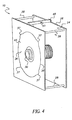
- cassette 10 has a body 24 (clearly shown in FIG. 4) having a base plate 26 and a plurality of spaced, upright, outwardly extending standoffs 28 fixedly attached at one end to the base plate 26.
- a hub member 30 is arranged substantially centered in the base plate 26 and extends outwardly therefrom.
- the hub member 30 has a diameter slightly smaller than the first, removed concentric section 18 of any one of said plurality of objects or end disks 12 to be stored thereon.
- a biased pusher plate 32 supports at least a portion of the loading side 20 (as shown in FIG. 1) of one of the plurality of objects or end disks 12 arranged about the hub member 30.
- the biased pusher plate 32 is biased preferably by spring 34 fixed against the base plate 26 and is slidable substantially in a plane substantially parallel to the base plate 26.
- the spring 34 is sized such that it is strong enough to push the stack 14 of end disks 12 as each is removed, but not too forceful to interfere with the removing of single end disks 12. With the material tested, a force between 1 lb. and 4 lbs. was acceptable. Other devices in place of springs could be used such as an air cylinder or a hydraulic cylinder which could apply constant force.
- Biased pusher plate 26 rides on bearings 11 and is slidable from a first position absent of supporting an object or end disk 12 thereon, to a second position supporting at least one of the objects or end disks mounted on the hub member 30.
- the outside diameter of the pusher plate 32 is preferably larger than the removed section 38 of the stripper plate 36 (described below), for it might push the last few end disks 12 through the second, removed concentric section 38 if it were smaller.
- a stripper plate 36 has a removed section 38 and a continuous edge 40 surrounding the removed section 38. It is important to our invention that second concentric section 38 has a diameter at least slightly smaller than the diameter of the end disks 12 for securing a top most object or end disk 12, on the hub member 30. Clearly shown in FIG. 2, stripper plate 36 is supported on an end 44 of the outwardly extending standoffs 28 for receiving and relieving the end disks 12 through the second concentric section 38.
- the removed section 38 of stripper plate 36 has a diameter smaller than the diameter of the removed concentric section 18 of end disks 12 so that the end disks 12 are retained but can be removed without permanently distorting the end disk material.
- a smaller diameter of removed concentric section 38 in stripper plate 36 would be desired.
- Relief pockets 37 can be cut into the stripper plate 36 opening to allow the material to escape easier with less deformation also allowing the second, removed concentric section 38 of stripper plate 36 to be even smaller.
- the relief pockets 37 must not expose the outer surface (OD) of the end disk 12.
- the relief pockets 37 could be of various shapes, such as rectangular, square, triangular, and circular.
- a source of air 48 is structurally associated with the body 24 of cassette 10, for instance base plate 26.
- the source of air 48 has an air nozzle 50 directed between the loading side 20 of the top most end disk 12 TM and the unloading side 22 of the nearest adjacent end disk 12 NA .
- a stream of air from air nozzle 50 causes the top most end disk 12 TM to lift from the hub member 30 through the second concentric section 38 of the stripper plate 36. More particularly, the air nozzle 50 is positioned such that the air is directed in a manner to separate the leading (the end disk being dispensed) and the trailing disk, allowing the leading end disk to be removed without also removing or even partially removing the trailing end disk.
- the air nozzle 50 may be directed perpendicular to the stack 14 of end disks 12 as long as only one end disk 12 is removed. It also could be directed at some angle (i.e. 45 degrees) along the stripper plate 36 back face such that the air flow would travel along the stripper plate 36 face creating the desired state mentioned above.
- the position of the air nozzle 50 relative to the stack of end disks 12 should be in an area where air is allowed to pass between the two end disks 12, but not where the vacuum suction cups (not shown) are applying force.
- the end disks 12 must be able to move or separate relative to each other. The pressure of the air must be great enough to force the materials away from each other but not so great as to force the end disks 12 through the second, removed concentric section 38 of stripper plate 36.
- the setting would depend on material characteristics of the end disk 12 (i.e. flexibility). For instance, we tested an end disk 12 having a laminate structure comprising HDPE. It was determined that a pressure between 30 psi and 60 psi could be used to separate adjacent end disks 12 in a stack 14. Moreover, the amount of overlap of the removed section 38 of stripper plate 36 as well as the relief pockets 37 in the stripper plate 36 relative to the OD of the end disk 12 have some bearing on air pressure setting.
- the end disks 12 are loaded onto the cylindrical end disk hub 30 about the removed concentric section 18 of the end disk 12.
- the end disks 12 are retained between the stripper plate 36 and the pusher plate 32 via pressure from pusher plate 32 spring 34.
- the pusher plate 32 and pusher plate bearing 11 index the end disks 12 to the pick position as each end disk 12 is removed.
- An air nozzle 50 supplies a blast of air that separates the ends as each end disk 12 is pulled through the stripper plate 36 and removed from the cassette 10.
- the air nozzle 50 is positioned such that it directs air in such a way to separate the leading and the lagging end disk 12.
- the removed section 38 in the stripper plate 36 is circular in shape and is slightly smaller in diameter than the end disk 12 outside diameter.
- the stripper plate 36 also has four relief pockets 37 to allow the end disk 12 to be pulled through without creasing the material as shown in FIG. 2.
Landscapes
- Engineering & Computer Science (AREA)
- Mechanical Engineering (AREA)
- Sheets, Magazines, And Separation Thereof (AREA)
- Packaging For Recording Disks (AREA)
- Projection-Type Copiers In General (AREA)
Abstract
Description
Claims (8)
- A storage and dispensing cassette for objects arranged in a stack, each said objects having a removed concentric section, a loading side and an opposed unloading side, said cassette comprising:a body having a base plate and a plurality of spaced, upright, outwardly extending standoffs, each one of said plurality of outwardly extending standoffs being fixedly attached at one end to said base plate;a hub member arranged substantially centered in said base plate and outwardly extending therefrom, said hub member having a diameter slightly smaller than the removed concentric section of any one of said objects to be stored thereon;a biased pusher plate for supporting at least a portion of said loading side of one of said objects arranged about said hub member, said biased pusher plate being biased against said base plate and slidable substantially along a plane substantially parallel to said hub member by a bearing arranged between said hub member and said pusher plate, said pusher plate moving from a first position absent of supporting at least one of said objects to a second position supporting at least one of said objects mounted on said hub member;a stripper plate having a removed section and a continuous edge surrounding said removed section, said removed section having a diameter at least slightly smaller than the diameter of said object for securing a top most object on said hub member, said stripper plate being supported on said ends of said outwardly extending standoffs for receiving and relieving said top most object through said removed section; and,a source of air structurally associated with said body, said source of air comprising an air outlet end directed between said loading side of said top most object nearest said stripper plate and said unloading side of a nearest adjacent object to said top most object for removing the top most object from said hub member through said removed section of said stripper plate.
- The cassette recited in claim 1 wherein said objects are substantially flat materials having a thickness in the range of .003 inches to .010 inches.
- The cassette recited in claim 2 wherein said objects are end disks having a substantially circular shape.
- The cassette recited in claim 1 wherein said stripper plate has a plurality of spaced recesses formed in an interior continuous edge for relieving said top most object from said removed section of said stripper plate without creasing said top most object.
- The cassette recited in claim 3 wherein a stack of end disks are arranged on said hub member and said air outlet is directed perpendicularly between a top most end disk and a nearest adjacent end disk in said stack of end disks.
- The cassette recited in claim 1 wherein said biased pusher plate is biased by a spring having a tension in the range of 1 pound to 4 pounds of force.
- The cassette recited in claim 1 wherein said biased pusher plate has a diameter larger than the diameter of said removed section of said stripper plate.
- A method of storing and dispensing a stack of end disks, each of said end disks having a removed concentric section, said method comprising the steps of:providing said cassette recited in claim 1;introducing said removed concentric section of at least one end disk about said hub member so that at least a portion of said loading side of the at least one end disk is supported on said biased pusher plate;arranging said stripper plate about said unloading side of said top most end disk; and,directing a stream of fluid to said loading side of said top most end disk and the unloading side of said next adjacent end disk in said stack so as to separate said top most end disk and said next adjacent end disk and to urge said top most end disks through said removed section of said stripper plate.
Applications Claiming Priority (2)
| Application Number | Priority Date | Filing Date | Title |
|---|---|---|---|
| US09/430,582 US6267264B1 (en) | 1999-10-29 | 1999-10-29 | Cassette and method for storing and dispensing objects arranged in a stack |
| US430582 | 1999-10-29 |
Publications (2)
| Publication Number | Publication Date |
|---|---|
| EP1095884A2 true EP1095884A2 (en) | 2001-05-02 |
| EP1095884A3 EP1095884A3 (en) | 2002-12-04 |
Family
ID=23708181
Family Applications (1)
| Application Number | Title | Priority Date | Filing Date |
|---|---|---|---|
| EP00203630A Withdrawn EP1095884A3 (en) | 1999-10-29 | 2000-10-18 | Cassette and method for storing and dispensing objects arranged in a stack |
Country Status (3)
| Country | Link |
|---|---|
| US (1) | US6267264B1 (en) |
| EP (1) | EP1095884A3 (en) |
| JP (1) | JP2001166429A (en) |
Families Citing this family (1)
| Publication number | Priority date | Publication date | Assignee | Title |
|---|---|---|---|---|
| PT1461784E (en) | 2001-12-31 | 2015-04-29 | Block Drug Co | Dispensers for tissue dilator devices |
Family Cites Families (13)
| Publication number | Priority date | Publication date | Assignee | Title |
|---|---|---|---|---|
| DE1152271B (en) * | 1961-11-16 | 1963-08-01 | Telefunken Patent | Cassette for automatic sequential playback of round, film-shaped recording media |
| US3391827A (en) * | 1967-02-15 | 1968-07-09 | Bextic Inc | Dispensing articles from a stack by fluid pressures |
| JPS4974095A (en) * | 1972-11-15 | 1974-07-17 | ||
| US4148395A (en) | 1977-12-05 | 1979-04-10 | Eastman Kodak Company | Roll package |
| US4142863A (en) * | 1978-06-05 | 1979-03-06 | Eastman Kodak Company | Article container for dispensing reagent slides |
| US4199076A (en) | 1978-06-26 | 1980-04-22 | Brown Jerry A | Cup dispenser |
| IT1202171B (en) * | 1985-07-22 | 1989-02-02 | Azionaria Costruzioni Acma Spa | DISTRIBUTOR OF GLASSES OF PLASTIC MATERIAL |
| JPS6236244A (en) * | 1985-08-08 | 1987-02-17 | Awa Eng Kk | Takeout device for stacked sheet-shaped disks |
| US5133171A (en) | 1991-10-30 | 1992-07-28 | Eastman Kodak Company | Light-tight packaging method for photosensitive web roll |
| US5383571A (en) * | 1993-10-08 | 1995-01-24 | Acry Fab Inc. | Lid dispenser |
| DE9319902U1 (en) * | 1993-12-24 | 1994-02-10 | Heidelberger Druckmaschinen Ag, 69115 Heidelberg | Device for supporting sheet separation in the upper area of a feeder stack |
| US5515970A (en) | 1995-01-23 | 1996-05-14 | Eastman Kodak Company | Light-tight package |
| US5960989A (en) * | 1996-10-15 | 1999-10-05 | Acry Fab, Inc. | Lid dispenser with dial adjustment and pivoting access door |
-
1999
- 1999-10-29 US US09/430,582 patent/US6267264B1/en not_active Expired - Fee Related
-
2000
- 2000-10-18 EP EP00203630A patent/EP1095884A3/en not_active Withdrawn
- 2000-10-27 JP JP2000328463A patent/JP2001166429A/en active Pending
Also Published As
| Publication number | Publication date |
|---|---|
| US6267264B1 (en) | 2001-07-31 |
| EP1095884A3 (en) | 2002-12-04 |
| JP2001166429A (en) | 2001-06-22 |
Similar Documents
| Publication | Publication Date | Title |
|---|---|---|
| US6422801B1 (en) | Automatic plate feeding system | |
| US5785309A (en) | Automatic plate feeding system and method | |
| CA2172099C (en) | Method and apparatus for applying edge protectors | |
| US6594970B1 (en) | Method and apparatus for wrapping palletized bundles | |
| US5078269A (en) | Wire shipping and dispensing container | |
| JPH0620888B2 (en) | Packaged coin roll, coin packaging method and coin packaging mechanism | |
| US5268059A (en) | Detaping machine for removal of integrated circuit devices from sealed pocket tape | |
| JPH04116059A (en) | Processing method for printed products deposited by misalignment and overlapping formation | |
| JP7337392B2 (en) | Apparatus for unstacking and spreading pharmaceuticals packaged in pouches | |
| US6267264B1 (en) | Cassette and method for storing and dispensing objects arranged in a stack | |
| EP1095882B1 (en) | Method of storing and dispensing thin, flimsy objects | |
| EP0681916B1 (en) | Method and apparatus for feeding print media | |
| US6290096B1 (en) | Article of manufacture for storing and dispensing an object | |
| JPS63232115A (en) | Packaging method and device for pressure-sensitive sheet material rolls | |
| US6969060B2 (en) | Sheet removal and conveying system | |
| JPH0822696B2 (en) | Plate material transfer method | |
| JP3571961B2 (en) | Body packaging device | |
| US20010032900A1 (en) | Apparatus for storing, transporting and delivering flat printing material for a machine processing such material | |
| US5906701A (en) | Apparatus and method for removal of adhesive-backed objects attached to a liner | |
| EP0209177B1 (en) | Graphic film package | |
| JPH0687556A (en) | Winding and unwinding method and device for printed matter | |
| JPH11265043A (en) | Method and device for packaging cartridge | |
| EP0897885B1 (en) | Method and apparatus for transporting sheet like products | |
| EP0219280B1 (en) | Method and apparatus for forming and wrapping a coin roll. | |
| JP3429021B2 (en) | Carry tape mounting device |
Legal Events
| Date | Code | Title | Description |
|---|---|---|---|
| PUAI | Public reference made under article 153(3) epc to a published international application that has entered the european phase |
Free format text: ORIGINAL CODE: 0009012 |
|
| AK | Designated contracting states |
Kind code of ref document: A2 Designated state(s): AT BE CH CY DE DK ES FI FR GB GR IE IT LI LU MC NL PT SE |
|
| AX | Request for extension of the european patent |
Free format text: AL;LT;LV;MK;RO;SI |
|
| PUAL | Search report despatched |
Free format text: ORIGINAL CODE: 0009013 |
|
| AK | Designated contracting states |
Kind code of ref document: A3 Designated state(s): AT BE CH CY DE DK ES FI FR GB GR IE IT LI LU MC NL PT SE |
|
| AX | Request for extension of the european patent |
Free format text: AL;LT;LV;MK;RO;SI |
|
| RIC1 | Information provided on ipc code assigned before grant |
Free format text: 7B 65H 1/26 A, 7B 65H 1/12 B, 7B 65H 3/08 B, 7B 65H 3/48 B, 7B 65H 3/34 B |
|
| AKX | Designation fees paid | ||
| 17P | Request for examination filed |
Effective date: 20030528 |
|
| RBV | Designated contracting states (corrected) |
Designated state(s): DE FR GB NL |
|
| REG | Reference to a national code |
Ref country code: DE Ref legal event code: 8566 |
|
| 17Q | First examination report despatched |
Effective date: 20040513 |
|
| STAA | Information on the status of an ep patent application or granted ep patent |
Free format text: STATUS: THE APPLICATION IS DEEMED TO BE WITHDRAWN |
|
| 18D | Application deemed to be withdrawn |
Effective date: 20040924 |