EP1095639A2 - Tibial knee component with a mobile bearing - Google Patents
Tibial knee component with a mobile bearing Download PDFInfo
- Publication number
- EP1095639A2 EP1095639A2 EP00203583A EP00203583A EP1095639A2 EP 1095639 A2 EP1095639 A2 EP 1095639A2 EP 00203583 A EP00203583 A EP 00203583A EP 00203583 A EP00203583 A EP 00203583A EP 1095639 A2 EP1095639 A2 EP 1095639A2
- Authority
- EP
- European Patent Office
- Prior art keywords
- bearing
- post
- tibial
- opening
- recess
- Prior art date
- Legal status (The legal status is an assumption and is not a legal conclusion. Google has not performed a legal analysis and makes no representation as to the accuracy of the status listed.)
- Granted
Links
Images


Classifications
-
- A—HUMAN NECESSITIES
- A61—MEDICAL OR VETERINARY SCIENCE; HYGIENE
- A61F—FILTERS IMPLANTABLE INTO BLOOD VESSELS; PROSTHESES; DEVICES PROVIDING PATENCY TO, OR PREVENTING COLLAPSING OF, TUBULAR STRUCTURES OF THE BODY, e.g. STENTS; ORTHOPAEDIC, NURSING OR CONTRACEPTIVE DEVICES; FOMENTATION; TREATMENT OR PROTECTION OF EYES OR EARS; BANDAGES, DRESSINGS OR ABSORBENT PADS; FIRST-AID KITS
- A61F2/00—Filters implantable into blood vessels; Prostheses, i.e. artificial substitutes or replacements for parts of the body; Appliances for connecting them with the body; Devices providing patency to, or preventing collapsing of, tubular structures of the body, e.g. stents
- A61F2/02—Prostheses implantable into the body
- A61F2/30—Joints
- A61F2/38—Joints for elbows or knees
- A61F2/3886—Joints for elbows or knees for stabilising knees against anterior or lateral dislocations
-
- A—HUMAN NECESSITIES
- A61—MEDICAL OR VETERINARY SCIENCE; HYGIENE
- A61F—FILTERS IMPLANTABLE INTO BLOOD VESSELS; PROSTHESES; DEVICES PROVIDING PATENCY TO, OR PREVENTING COLLAPSING OF, TUBULAR STRUCTURES OF THE BODY, e.g. STENTS; ORTHOPAEDIC, NURSING OR CONTRACEPTIVE DEVICES; FOMENTATION; TREATMENT OR PROTECTION OF EYES OR EARS; BANDAGES, DRESSINGS OR ABSORBENT PADS; FIRST-AID KITS
- A61F2/00—Filters implantable into blood vessels; Prostheses, i.e. artificial substitutes or replacements for parts of the body; Appliances for connecting them with the body; Devices providing patency to, or preventing collapsing of, tubular structures of the body, e.g. stents
- A61F2/02—Prostheses implantable into the body
- A61F2/30—Joints
- A61F2/38—Joints for elbows or knees
- A61F2/3868—Joints for elbows or knees with sliding tibial bearing
Definitions
- the present invention relates to an orthopaedic implant, and, more particularly, to a tibial knee component.
- a tibial knee component is implanted within a proximal tibia and engages with a femoral component implanted within a distal femur.
- the tibial knee component typically includes a bearing which is immovably affixed to a tibial tray.
- the tibial tray includes a stem which is implanted within the intramedullary (IM) canal in the proximal tibia.
- the bearing may be in the form of a wear resistant and low friction material such as ultra high molecular weight polyethylene (UHMWPE) which is immovably attached to the tibial tray. Pivotal movement between the femoral component and the bearing surface of the bearing occurs with relatively low friction and low wear characteristics.
- UHMWPE ultra high molecular weight polyethylene
- a tibial knee component with a mobile bearing which is easier to manufacture and still allows adequate movement between the bearing and tibial tray during deep flexion of the knee joint.
- the present invention provides a tibial knee component with a tibial tray having a post and keyhole shaped recess, and a bearing having a projection positioned within the recess and an opening receiving the post.
- the invention comprises, in one form thereof, an orthopaedic knee component for implanting within a proximal tibia.
- a tibial tray includes a proximal tibial plateau and a distally extending stem.
- the tibial tray also includes a recess extending into the tibial plateau.
- the recess is configured to define a first rotational stop and a second rotational stop.
- the tibial tray further includes a generally cylindrical post positioned within the recess. The post extends generally orthogonal to the tibial plateau and defines an axis of rotation.
- a bearing is carried by the tibial tray and has an articular bearing surface for engagement with a femoral component.
- the bearing has an opening in which the post is disposed.
- the opening and the post allow pivotal movement of the bearing relative to the tibial plateau about the axis of rotation.
- the bearing further has a projection extending into the recess of the tibial tray. The projection is configured to abut the first rotational stop when the bearing is at a first rotational limit and is configured to abut the second rotational stop when the bearing is at a second rotational limit.
- An advantage of the present invention is that the keyhole shaped recess and projection allow rotation of the bearing between first and second rotational limits.
- Another advantage is that the post and opening allow rotational movement of the bearing while not allowing radial movement of the bearing relative to the axis of rotation.
- Yet another advantage is that substantially all of the bearing backing is supported by the tibial plateau at any pivotal position.
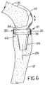
- an orthopaedic knee component in the form of a tibial knee component 10 which is implanted within a proximal tibia 12 (Fig. 6).
- Tibial knee component 10 engages with a femoral knee component 14 which is implanted within a distal femur 16.
- Tibial knee component 10 includes a tibial tray 18 and a bearing 20.
- Tibial tray 18 has a proximal tibial plateau 22 and a distally extending stem 24.
- Tibial plateau 22 has a generally planar proximal surface which extends transverse (e.g., orthogonal) to a longitudinal axis 26 of stem 24.
- a generally cylindrical shaped post 28 has an axis of rotation 30 which extends generally orthogonal to tibial plateau 22, and thus also extends generally parallel to axis 26 of stem 24.
- Tibial tray 18 also includes a key-hole shaped recess 32 which extends into tibial plateau 22.
- Recess 32 has a first wall 33 providing a first rotational stop when tibial tray is engaged with bearing 20, and a second wall 35 providing a second rotation stop when tibial tray is engaged with bearing 20, as will be described in more detail hereinafter.
- Recess 32 may have any suitable configuration.
- Post 28 is positioned within and extends from recess 32 to define axis of rotation 30.
- Bearing 20 has an articular bearing surface 34 for engagement with femoral component 14.
- Articular bearing surface 34 is disposed on either side of a center projection 36.
- Each discrete portion of articular bearing surface 34 on either side of projection 36 engages a corresponding condyle of femoral knee component 14, with projection 36 being disposed between the condyles.
- Bearing 20 also includes a generally cylindrical shaped opening 38 in which post 28 is disposed. Opening 38 and post 28 allow pivotal movement of bearing 20 relative to tibial plateau 22 about axis of rotation 30 of post 28. Opening 38 has a diameter which is just slightly larger than an outside diameter of post 28, such that movement of bearing 20 in a generally radial direction relative to axis 30 is inhibited.
- Bearing 20 also includes an projection 44 extending into recess 32.
- Projection 44 and recess 32 allow pivotal movement of bearing 20 between a first rotational limit and a second rotational limit about axis of rotation 30.
- projection 44 has a generally rectangular shape when viewed in a direction parallel to axis of rotation 30.
- projection 44 may have any suitable configuration allowing movement of bearing 20 relative to articular bearing surface 34 (e.g., pin shaped, etc.).
- Bearing 20 is shown in Fig. 3 at a first rotational limit which is approximately 25° relative to a neutral or symmetric position shown in Fig. 2.
- bearing 20 is pivotally movable through an angle of approximately 50° between the first rotational limit and the second rotational limit (in a direction opposite to that shown in Fig. 3).
- Bearing 20 has a backing 46 which engages with tibial plateau 22.
- Backing 46 is generally planar to match the corresponding generally planar configuration of tibial plateau 22.
- Backing 46 defines a load bearing surface with tibial plateau which transfers the load imparted either by tibial plateau 22 or the femoral condyles engaging articular bearing surface 34.
- Backing 46 is sized and configured such that backing 46 is substantially entirely supported by tibial plateau 22 at any position during pivotal movement between the first rotational limit and the second rotational limit. As illustrated in Fig. 2, backing 46 of bearing 20 is entirely supported by tibial plateau 22 when bearing 20 is at a neutral position. Similarly, backing 46 is substantially entirely supported by tibial plateau 22 when bearing 20 is at a first rotational limit (Fig. 3), a second rotational limit, or any position therebetween.
- the tibial tray includes a notch on the posterior side such that the tibial plateau has a generally U-shape when viewed in a proximal-distal direction.
- the bearing may overhang the tibial tray by a substantial amount when the bearing is at a rotational limit.
- tibial plateau 22 of the present invention does not include a notch on the posterior side and the bearing does not overhang the tibial plateau by any appreciable amount when at a first rotational limit or a second rotational limit.
- bearing 20 is better supported and wear between backing 46 and tibial plateau 22 is reduced.
Landscapes
- Health & Medical Sciences (AREA)
- Orthopedic Medicine & Surgery (AREA)
- Physical Education & Sports Medicine (AREA)
- Cardiology (AREA)
- Oral & Maxillofacial Surgery (AREA)
- Transplantation (AREA)
- Engineering & Computer Science (AREA)
- Biomedical Technology (AREA)
- Heart & Thoracic Surgery (AREA)
- Vascular Medicine (AREA)
- Life Sciences & Earth Sciences (AREA)
- Animal Behavior & Ethology (AREA)
- General Health & Medical Sciences (AREA)
- Public Health (AREA)
- Veterinary Medicine (AREA)
- Prostheses (AREA)
Abstract
Description
Claims (8)
- An orthopaedic knee component for implanting within a proximal tibia, which comprises:a tibial tray having a proximal tibial plateau, a distally extending stem, and a recess extending into the tibial plateau and configured to define a first rotational stop and a second rotational stop, said tibial tray further including a generally cylindrical post positioned within said recess , said post extending generally orthogonal to said tibial plateau and defining an axis of rotation; anda bearing carried by said tibial tray and having an articular bearing surface for engagement with a femoral component, said bearing having an opening in which said post is disposed, said opening and said post allowing pivotal movement of said bearing relative to said tibial plateau about said axis of rotation, said bearing further having a projection extending into said recess of said tibial tray, said projection configured to abut said first rotational stop when said bearing is at a first rotational limit and configured to abut said second rotational stop when said bearing is at a second rotational limit.
- The orthopaedic knee component of claim 1, wherein said recess is key-hole shaped.
- The orthopaedic knee component of claim 1, wherein said projection is rectangular shaped when viewed in a direction parallel to said axis of rotation.
- The orthopaedic knee component of claim 1, wherein said bearing is pivotally movable through an angle of approximately 50° between said first rotational limit and said second rotational limit.
- The orthopaedic knee component of claim 1, wherein each of said post and said opening are generally cylindrical shaped.
- The orthopaedic knee component of claim 1, wherein said of claim 5, wherein said opening in said bearing is sized to substantially inhibit movement of said bearing relative to said tibial plateau in a generally radial direction relative to said axis of rotation.
- The orthopaedic knee component of claim 6, wherein said opening includes a first diameter corresponding to a diameter of said post.
- An orthopaedic knee component for implanting within a proximal tibia, comprising:a tibial tray having a proximal tibial plateau and a distally extending stem, said tibial tray including one of:a recess having a first wall defining a first rotational stop and a second wall defining a second rotational stop; anda projection for extending into said recess; said tibial tray also including one of:an opening; anda generally cylindrical post for extending into said opening, said post defining an axis of rotation and extending generally orthogonal to said tibial plateau; anda bearing carried by said tibial tray and having an articular bearing surface for engagement with a femoral component, said bearing including a mating one of said recess and said projection, and also including a mating one of said opening and said post, said post being disposed within said opening, said opening and said post allowing pivotal movement of said bearing relative to said tibial plateau about said axis of rotation, said projection configured to abut said first rotational stop when said bearing is at a first rotational limit and configured to abut said second rotational stop when said bearing is at a second rotational limit.
Applications Claiming Priority (2)
| Application Number | Priority Date | Filing Date | Title |
|---|---|---|---|
| US421869 | 1999-10-26 | ||
| US09/421,869 US6210444B1 (en) | 1999-10-26 | 1999-10-26 | Tibial knee component with a mobile bearing |
Publications (3)
| Publication Number | Publication Date |
|---|---|
| EP1095639A2 true EP1095639A2 (en) | 2001-05-02 |
| EP1095639A3 EP1095639A3 (en) | 2002-06-26 |
| EP1095639B1 EP1095639B1 (en) | 2005-03-09 |
Family
ID=23672395
Family Applications (1)
| Application Number | Title | Priority Date | Filing Date |
|---|---|---|---|
| EP00203583A Expired - Lifetime EP1095639B1 (en) | 1999-10-26 | 2000-10-16 | Tibial knee component with a mobile bearing |
Country Status (4)
| Country | Link |
|---|---|
| US (1) | US6210444B1 (en) |
| EP (1) | EP1095639B1 (en) |
| DE (1) | DE60018523T2 (en) |
| ES (1) | ES2235768T3 (en) |
Families Citing this family (60)
| Publication number | Priority date | Publication date | Assignee | Title |
|---|---|---|---|---|
| US6428577B1 (en) * | 1998-05-20 | 2002-08-06 | Smith & Nephew, Inc. | Mobile bearing knee prosthesis |
| US6660039B1 (en) | 1998-05-20 | 2003-12-09 | Smith & Nephew, Inc. | Mobile bearing knee prosthesis |
| US6413279B1 (en) | 1999-03-01 | 2002-07-02 | Biomet, Inc. | Floating bearing knee joint prosthesis with a fixed tibial post |
| US6972039B2 (en) | 1999-03-01 | 2005-12-06 | Biomet, Inc. | Floating bearing knee joint prosthesis with a fixed tibial post |
| US20050209703A1 (en) * | 1999-04-02 | 2005-09-22 | Fell Barry M | Surgically implantable prosthetic system |
| US6966928B2 (en) * | 1999-05-10 | 2005-11-22 | Fell Barry M | Surgically implantable knee prosthesis having keels |
| US7338524B2 (en) * | 1999-05-10 | 2008-03-04 | Fell Barry M | Surgically implantable knee prosthesis |
| US7491235B2 (en) * | 1999-05-10 | 2009-02-17 | Fell Barry M | Surgically implantable knee prosthesis |
| US20050033424A1 (en) * | 1999-05-10 | 2005-02-10 | Fell Barry M. | Surgically implantable knee prosthesis |
| US7297161B2 (en) * | 1999-05-10 | 2007-11-20 | Fell Barry M | Surgically implantable knee prosthesis |
| DE19950112A1 (en) * | 1999-10-18 | 2001-04-19 | Plus Endoprothetik Ag Rotkreuz | Knee joint endoprosthesis |
| US6558426B1 (en) | 2000-11-28 | 2003-05-06 | Medidea, Llc | Multiple-cam, posterior-stabilized knee prosthesis |
| DE10109804C2 (en) * | 2001-03-01 | 2003-04-03 | Mathys Medizinaltechnik Ag Bet | joint prosthesis |
| US6530957B1 (en) * | 2001-08-23 | 2003-03-11 | Howmedica Osteonics Corp. | Modular joint prosthesis with multiple offset humeral head component and method |
| DE10200263B4 (en) * | 2002-01-07 | 2007-01-25 | Plus Orthopedics Ag | Tibial component of a knee joint endoprosthesis |
| US20040034432A1 (en) * | 2002-02-11 | 2004-02-19 | Dean Hughes | Mobile bearing tibial base prosthetic devices employing oxidized zirconium surfaces |
| US7799086B2 (en) * | 2002-04-25 | 2010-09-21 | Zimmer Technology, Inc. | Modular bone implant, tools, and method |
| US20040024471A1 (en) * | 2002-06-27 | 2004-02-05 | Ferree Bret A. | Bone cell covered arthroplasty devices |
| AU2003287190A1 (en) | 2002-10-23 | 2004-05-13 | Alastair J. T. Clemow | Modular femoral component for a total knee joint replacement for minimally invasive implantation |
| EP1601316A1 (en) * | 2003-02-04 | 2005-12-07 | Zimmer Austin, Inc. | Rotating/non-rotating tibia plate/insert system |
| US6986791B1 (en) | 2003-04-15 | 2006-01-17 | Biomet Manufacturing Corp. | Knee prosthesis with moveable post |
| US7534270B2 (en) * | 2003-09-03 | 2009-05-19 | Integra Lifesciences Corporation | Modular total ankle prosthesis apparatuses and methods |
| US7261740B2 (en) * | 2003-10-29 | 2007-08-28 | Wright Medical Technology, Inc. | Tibial knee prosthesis |
| WO2005069957A2 (en) * | 2004-01-20 | 2005-08-04 | Alexander Michalow | Unicondylar knee implant |
| US20060142870A1 (en) * | 2004-08-19 | 2006-06-29 | Shawn Robinson | Modular total ankle prosthesis apparatuses, systems and methods, and systems and methods for bone resection and prosthetic implantation |
| CN101351172B (en) * | 2005-10-31 | 2013-10-23 | 德普伊产品公司 | Modular fixed and mobile bearing prosthesis system |
| EP1787603A1 (en) | 2005-11-18 | 2007-05-23 | Zimmer GmbH | Basis-platform for an artificial joint |
| US20080091271A1 (en) * | 2006-10-13 | 2008-04-17 | Bonitati John A | Mobile/fixed prosthetic knee systems |
| US20080091272A1 (en) * | 2006-10-13 | 2008-04-17 | Aram Luke J | Mobile/fixed prosthetic knee systems |
| US20080091273A1 (en) * | 2006-10-13 | 2008-04-17 | Hazebrouck Stephen A | Mobile/fixed prosthetic knee systems |
| US20080114463A1 (en) * | 2006-10-13 | 2008-05-15 | Auger Daniel D | Mobile/fixed prosthetic knee systems |
| US7740662B2 (en) * | 2006-10-13 | 2010-06-22 | Depuy Products, Inc. | Mobile/fixed prosthetic knee systems |
| US8177849B2 (en) | 2007-05-07 | 2012-05-15 | Zimmer, Inc. | Methods and apparatuses for attaching tissue to orthopaedic implants |
| JP5584115B2 (en) | 2007-05-15 | 2014-09-03 | フェル バリー エム | Surgical implantable knee joint with restraint keel |
| US8128703B2 (en) * | 2007-09-28 | 2012-03-06 | Depuy Products, Inc. | Fixed-bearing knee prosthesis having interchangeable components |
| US8715359B2 (en) | 2009-10-30 | 2014-05-06 | Depuy (Ireland) | Prosthesis for cemented fixation and method for making the prosthesis |
| US7628818B2 (en) * | 2007-09-28 | 2009-12-08 | Depuy Products, Inc. | Fixed-bearing knee prosthesis having interchangeable components |
| US20110035017A1 (en) * | 2007-09-25 | 2011-02-10 | Depuy Products, Inc. | Prosthesis with cut-off pegs and surgical method |
| US20110035018A1 (en) * | 2007-09-25 | 2011-02-10 | Depuy Products, Inc. | Prosthesis with composite component |
| US8632600B2 (en) | 2007-09-25 | 2014-01-21 | Depuy (Ireland) | Prosthesis with modular extensions |
| US20090088861A1 (en) * | 2007-09-27 | 2009-04-02 | Finsbury (Development) Limited | Prosthesis |
| US9204967B2 (en) | 2007-09-28 | 2015-12-08 | Depuy (Ireland) | Fixed-bearing knee prosthesis having interchangeable components |
| US9119723B2 (en) | 2008-06-30 | 2015-09-01 | Depuy (Ireland) | Posterior stabilized orthopaedic prosthesis assembly |
| US8236061B2 (en) | 2008-06-30 | 2012-08-07 | Depuy Products, Inc. | Orthopaedic knee prosthesis having controlled condylar curvature |
| US8192498B2 (en) | 2008-06-30 | 2012-06-05 | Depuy Products, Inc. | Posterior cructiate-retaining orthopaedic knee prosthesis having controlled condylar curvature |
| US8187335B2 (en) | 2008-06-30 | 2012-05-29 | Depuy Products, Inc. | Posterior stabilized orthopaedic knee prosthesis having controlled condylar curvature |
| US8206451B2 (en) | 2008-06-30 | 2012-06-26 | Depuy Products, Inc. | Posterior stabilized orthopaedic prosthesis |
| US9168145B2 (en) | 2008-06-30 | 2015-10-27 | Depuy (Ireland) | Posterior stabilized orthopaedic knee prosthesis having controlled condylar curvature |
| US8828086B2 (en) | 2008-06-30 | 2014-09-09 | Depuy (Ireland) | Orthopaedic femoral component having controlled condylar curvature |
| US8152853B2 (en) | 2009-06-05 | 2012-04-10 | Biomet Manufacturing Corp. | Knee prosthesis with rotatable post |
| US9011547B2 (en) * | 2010-01-21 | 2015-04-21 | Depuy (Ireland) | Knee prosthesis system |
| US8308808B2 (en) | 2010-02-19 | 2012-11-13 | Biomet Manufacturing Corp. | Latent mobile bearing for prosthetic device |
| US8545571B2 (en) | 2010-07-30 | 2013-10-01 | Howmedica Osteonics Corp. | Stabilized knee prosthesis |
| US8617250B2 (en) * | 2011-06-17 | 2013-12-31 | Biomet Manufacturing, Llc | Revision knee tibial locking mechanism |
| US8663334B2 (en) * | 2012-05-31 | 2014-03-04 | Howmedica Osteonics Corp. | Lateral entry insert for cup trial |
| US8906102B2 (en) | 2012-05-31 | 2014-12-09 | Howmedica Osteonics Corp. | Lateral entry insert for cup trial |
| GB2524668A (en) | 2012-09-10 | 2015-09-30 | Acumed Llc | Radial head prosthesis with floating articular member |
| US9763792B2 (en) | 2015-10-01 | 2017-09-19 | Acumed Llc | Radial head prosthesis with rotate-to-lock interface |
| US11116641B2 (en) | 2019-02-05 | 2021-09-14 | Depuy Ireland Unlimited Company | Orthopaedic prosthetic system for a rotating hinged-knee prosthesis |
| US11033396B2 (en) * | 2019-02-05 | 2021-06-15 | Depuy Ireland Unlimited Company | Orthopaedic prosthetic system for a rotating hinged-knee prosthesis |
Family Cites Families (75)
| Publication number | Priority date | Publication date | Assignee | Title |
|---|---|---|---|---|
| US4085466A (en) | 1974-11-18 | 1978-04-25 | National Research Development Corporation | Prosthetic joint device |
| US4219893A (en) | 1977-09-01 | 1980-09-02 | United States Surgical Corporation | Prosthetic knee joint |
| US4301553A (en) | 1975-08-15 | 1981-11-24 | United States Surgical Corporation | Prosthetic knee joint |
| US4094017A (en) | 1977-02-16 | 1978-06-13 | Larry Stanford Matthews | Knee joint prosthesis with patellar-femoral contact |
| US4136405A (en) | 1977-04-29 | 1979-01-30 | Zimmer U.S.A. | Rotational offset knee prosthesis |
| US4216549A (en) | 1977-06-02 | 1980-08-12 | Purdue Research Foundation | Semi-stable total knee prosthesis |
| US4470158A (en) | 1978-03-10 | 1984-09-11 | Biomedical Engineering Corp. | Joint endoprosthesis |
| US4224697A (en) | 1978-09-08 | 1980-09-30 | Hexcel Corporation | Constrained prosthetic knee |
| US4224696A (en) | 1978-09-08 | 1980-09-30 | Hexcel Corporation | Prosthetic knee |
| US4257129A (en) | 1979-05-21 | 1981-03-24 | Volz Robert G | Prosthetic knee joint tibial implant |
| US4309778A (en) | 1979-07-02 | 1982-01-12 | Biomedical Engineering Corp. | New Jersey meniscal bearing knee replacement |
| FR2465470A1 (en) | 1979-08-07 | 1981-03-27 | Gauthier Georges | Articulated joint surgical prosthesis - has twin spherical surfaces in each mating part with prolongations for lateral movement |
| US4262368A (en) | 1979-09-24 | 1981-04-21 | Wright Manufacturing Company | Rotating and hinged knee prosthesis |
| JPS6077752A (en) | 1983-09-30 | 1985-05-02 | 東海林 宏 | Meniscal artificial knee joint |
| US4634444A (en) | 1984-02-09 | 1987-01-06 | Joint Medical Products Corporation | Semi-constrained artificial joint |
| SE450460B (en) | 1984-11-28 | 1987-06-29 | Albrektsson Bjoern | DEVICE IN ARTIFICIAL MENISH FOR A KNEE JOINT PROTECTION |
| GB8432267D0 (en) | 1984-12-20 | 1985-01-30 | Thackray C F Ltd | Knee prosthesis |
| US4888021A (en) | 1988-02-02 | 1989-12-19 | Joint Medical Products Corporation | Knee and patellar prosthesis |
| US5011496A (en) | 1988-02-02 | 1991-04-30 | Joint Medical Products Corporation | Prosthetic joint |
| FR2631814A1 (en) * | 1988-05-31 | 1989-12-01 | Scernp | SLIDING KNEE PROSTHESIS |
| US5171283A (en) | 1989-07-11 | 1992-12-15 | Biomedical Engineering Trust | Compound shape rotating bearing |
| GB9005496D0 (en) | 1990-03-12 | 1990-05-09 | Howmedica | Tibial component for a replacement knee prosthesis and total knee prosthesis incorporating such a component |
| US5358531A (en) | 1990-06-12 | 1994-10-25 | British Technology Group Limited | Prosthetic knee joint devices |
| FR2664492A1 (en) | 1990-07-11 | 1992-01-17 | Bousquet Gilles | BICONDYLIAN KNEE PROSTHESIS. |
| US5370701A (en) | 1990-09-28 | 1994-12-06 | Arch Development Corporation | Rotating/sliding contrained prosthetic knee |
| DE69128961T2 (en) | 1990-11-14 | 1998-10-08 | Arch Development Corp., Chicago, Ill. | IMPROVED KNEE PROSTHESIS WITH MOVABLE BEARING |
| GB9102348D0 (en) | 1991-02-04 | 1991-03-20 | Inst Of Orthopaedics The | Prosthesis for knee replacement |
| US5609639A (en) | 1991-02-04 | 1997-03-11 | Walker; Peter S. | Prosthesis for knee replacement |
| GB9314839D0 (en) | 1993-07-16 | 1993-09-01 | Walker Peter S | Prosthesis for knee replacement |
| US5358527A (en) | 1991-03-22 | 1994-10-25 | Forte Mark R | Total knee prosthesis with resurfacing and posterior stabilization capability |
| US5395401A (en) | 1991-06-17 | 1995-03-07 | Bahler; Andre | Prosthetic device for a complex joint |
| US5282868A (en) | 1991-06-17 | 1994-02-01 | Andre Bahler | Prosthetic arrangement for a complex joint, especially knee joint |
| DE4202717C1 (en) | 1991-12-11 | 1993-06-17 | Dietmar Prof. Dr. 3350 Kreiensen De Kubein-Meesenburg | |
| DE4141757C1 (en) | 1991-12-18 | 1993-07-15 | Eska Medical Gmbh & Co, 2400 Luebeck, De | |
| CH686401A5 (en) | 1992-01-14 | 1996-03-29 | Wehrli Ueli Dr | Meniscus platform for an artificial knee joint. |
| ATE176145T1 (en) | 1992-01-14 | 1999-02-15 | Sulzer Orthopaedie Ag | MENISCUS PLATFORM FOR ARTIFICIAL KNEE JOINT |
| CH686400A5 (en) | 1992-01-14 | 1996-03-29 | Sulzer Medizinaltechnik Ag | Meniscus platform for an artificial knee joint. |
| NZ243181A (en) | 1992-04-23 | 1994-10-26 | Michael John Pappas | Prosthetic joint with guide means to limit articulation of a first element and bearing means to two degrees of freedom |
| US5271737A (en) * | 1992-09-04 | 1993-12-21 | U.S. Medical Products, Inc. | Tibial prosthetic implant with offset stem |
| DE9212879U1 (en) | 1992-09-24 | 1994-01-27 | Waldemar Link GmbH & Co, 22339 Hamburg | Knee joint endoprosthesis to replace the shin joint surfaces |
| US5344460A (en) | 1992-10-30 | 1994-09-06 | Encore Orthopedics, Inc. | Prosthesis system |
| US5314481A (en) | 1992-11-12 | 1994-05-24 | Wright Medical Technology, Inc. | Hinged knee prosthesis with extended patellar track |
| US5658342A (en) | 1992-11-16 | 1997-08-19 | Arch Development | Stabilized prosthetic knee |
| US5413604A (en) | 1992-12-24 | 1995-05-09 | Osteonics Corp. | Prosthetic knee implant for an anterior cruciate ligament deficient total knee replacement |
| US5358530A (en) | 1993-03-29 | 1994-10-25 | Zimmer, Inc. | Mobile bearing knee |
| GB2277034B (en) | 1993-04-01 | 1997-02-26 | British Tech Group | Implantable prosthetic patellar components |
| GB2278782A (en) | 1993-04-20 | 1994-12-14 | Kevin Hardinge | An improved knee arthroplasty and tibial component therefor |
| GB9310193D0 (en) | 1993-05-18 | 1993-06-30 | Walker Peter S | Knee prosthesis with femoral,tibial conformity |
| IT1264820B1 (en) | 1993-07-28 | 1996-10-10 | Cremascoli G Srl | TOTAL KNEE PROSTHESIS TOTAL KNEE PROSTHESIS |
| FR2714819B1 (en) | 1994-01-10 | 1996-03-08 | Billy Jean Louis | Knee prosthesis. |
| GB9403165D0 (en) | 1994-02-18 | 1994-04-06 | Johnson Robert | Knee joint prostheses |
| DE4409787A1 (en) * | 1994-03-22 | 1995-09-28 | Alphanorm Medizintechnik Gmbh | Knee prosthesis |
| GB9405746D0 (en) | 1994-03-23 | 1994-05-11 | Howmedica | Prosthetic patello femoral joint assembly |
| GB9405883D0 (en) | 1994-03-24 | 1994-05-11 | Corin Medical Ltd | Prosthesis assembly |
| FR2718015B1 (en) | 1994-03-29 | 1996-07-05 | Bouvet Jean Claude | Improvement to knee prostheses. |
| GB9407153D0 (en) | 1994-04-11 | 1994-06-01 | Corin Medical Ltd | Unicompartmental knee prosthesis |
| FR2719466B1 (en) | 1994-05-04 | 1997-06-06 | Ysebaert Sa | Knee prosthesis with movable meniscus. |
| GB9413607D0 (en) | 1994-07-06 | 1994-08-24 | Goodfellow John W | Endoprosthetic knee joint device |
| GB9415180D0 (en) | 1994-07-28 | 1994-09-21 | Walker Peter S | Stabilised mobile bearing knee |
| GB9418492D0 (en) | 1994-09-14 | 1994-11-02 | Goodfellow John W | Prosthetic knee joint device |
| US5549689A (en) | 1994-11-28 | 1996-08-27 | Epstein; Norman | Prosthetic knee |
| US5683468A (en) | 1995-03-13 | 1997-11-04 | Pappas; Michael J. | Mobile bearing total joint replacement |
| FR2735017B1 (en) * | 1995-06-08 | 1997-08-14 | Groupe Lepine | KNEE PROSTHESIS WITH MOBILE TRAY |
| GB2304051B (en) | 1995-08-09 | 1999-01-27 | Corin Medical Ltd | A knee prosthesis |
| DE19606462C1 (en) * | 1996-02-21 | 1997-10-16 | Plus Endoprothetik Ag | Knee joint endoprosthesis |
| ES2165538T3 (en) * | 1996-02-21 | 2002-03-16 | Plus Endoprothetik Ag | ENDOPROTESIS OF THE ARTICULATION OF THE KNEE. |
| GB2312168B (en) | 1996-04-17 | 1999-11-03 | Finsbury | Meniscal knee prosthesis |
| GB2312167A (en) | 1996-04-17 | 1997-10-22 | Finsbury | An endoprosthetic knee |
| GB2312166A (en) | 1996-04-17 | 1997-10-22 | Finsbury | Tibial plate for an endoprosthetic knee |
| GB2312377B (en) | 1996-04-24 | 2000-04-26 | Roozbeh Shirandami | Prosthetic knee joint with anterior posterior sliding action |
| GB9609609D0 (en) | 1996-05-08 | 1996-07-10 | Midland International Orthopae | Knee prosthesis |
| GB9611059D0 (en) | 1996-05-28 | 1996-07-31 | Howmedica | Tibial element for a replacement knee prosthesis |
| US5964808A (en) * | 1996-07-11 | 1999-10-12 | Wright Medical Technology, Inc. | Knee prosthesis |
| US5951603A (en) * | 1997-09-25 | 1999-09-14 | Johnson & Johnson Professional, Inc. | Rotatable joint prosthesis with axial securement |
| US6090144A (en) * | 1998-05-12 | 2000-07-18 | Letot; Patrick | Synthetic knee system |
-
1999
- 1999-10-26 US US09/421,869 patent/US6210444B1/en not_active Expired - Lifetime
-
2000
- 2000-10-16 EP EP00203583A patent/EP1095639B1/en not_active Expired - Lifetime
- 2000-10-16 ES ES00203583T patent/ES2235768T3/en not_active Expired - Lifetime
- 2000-10-16 DE DE60018523T patent/DE60018523T2/en not_active Expired - Lifetime
Also Published As
| Publication number | Publication date |
|---|---|
| ES2235768T3 (en) | 2005-07-16 |
| EP1095639A3 (en) | 2002-06-26 |
| US6210444B1 (en) | 2001-04-03 |
| DE60018523T2 (en) | 2006-04-13 |
| EP1095639B1 (en) | 2005-03-09 |
| DE60018523D1 (en) | 2005-04-14 |
Similar Documents
| Publication | Publication Date | Title |
|---|---|---|
| US6210444B1 (en) | Tibial knee component with a mobile bearing | |
| US6210445B1 (en) | Tibial knee component with a mobile bearing | |
| US6217618B1 (en) | Tibial knee component with a mobile bearing | |
| EP1064889B1 (en) | Tibial knee component with a mobile bearing | |
| JP4509998B2 (en) | Knee joint prosthesis | |
| EP0732091B1 (en) | Mobile bearing total joint replacement | |
| US6491726B2 (en) | Posterior stabilized prosthetic knee replacement with bearing translation and dislocation prevention features | |
| US6939380B2 (en) | Mobile talar component for total ankle replacement implant | |
| JP4820547B2 (en) | Self-aligning knee prosthesis | |
| US6206926B1 (en) | Prosthetic knee joint with enhanced posterior stabilization and dislocation prevention features | |
| EP1333785B1 (en) | Floating bearing knee joint prosthesis with a fixed tibial post | |
| US5755801A (en) | Prostheses for knee replacement | |
| US6080195A (en) | Rotatable and translatable joint prosthesis with posterior stabilization | |
| US5480445A (en) | Interlocking tibial prosthesis | |
| CA2233265F (en) | Deep flexion knee prosthesis | |
| US8545570B2 (en) | Hinged joint system | |
| US9452051B2 (en) | Stabilized knee prosthesis | |
| US20130035765A1 (en) | Total knee arthroplasty with symmetric femoral implant having double q-angle trochlear groove | |
| CA2254218C (en) | Prosthetic knee joint with enhanced posterior stabilization and dislocation prevention features | |
| EP0838204A2 (en) | Prosthetic knee joint with enhanced posterior stabilization |
Legal Events
| Date | Code | Title | Description |
|---|---|---|---|
| PUAI | Public reference made under article 153(3) epc to a published international application that has entered the european phase |
Free format text: ORIGINAL CODE: 0009012 |
|
| AK | Designated contracting states |
Kind code of ref document: A2 Designated state(s): AT BE CH CY DE DK ES FI FR GB GR IE IT LI LU MC NL PT SE |
|
| AX | Request for extension of the european patent |
Free format text: AL;LT;LV;MK;RO;SI |
|
| PUAL | Search report despatched |
Free format text: ORIGINAL CODE: 0009013 |
|
| AK | Designated contracting states |
Kind code of ref document: A3 Designated state(s): AT BE CH CY DE DK ES FI FR GB GR IE IT LI LU MC NL PT SE |
|
| AX | Request for extension of the european patent |
Free format text: AL;LT;LV;MK;RO;SI |
|
| 17P | Request for examination filed |
Effective date: 20021219 |
|
| AKX | Designation fees paid |
Designated state(s): DE ES FR GB IT |
|
| RAP1 | Party data changed (applicant data changed or rights of an application transferred) |
Owner name: ZIMMER TECHNOLOGY, INC. |
|
| 17Q | First examination report despatched |
Effective date: 20040416 |
|
| GRAP | Despatch of communication of intention to grant a patent |
Free format text: ORIGINAL CODE: EPIDOSNIGR1 |
|
| GRAS | Grant fee paid |
Free format text: ORIGINAL CODE: EPIDOSNIGR3 |
|
| GRAA | (expected) grant |
Free format text: ORIGINAL CODE: 0009210 |
|
| AK | Designated contracting states |
Kind code of ref document: B1 Designated state(s): DE ES FR GB IT |
|
| REG | Reference to a national code |
Ref country code: GB Ref legal event code: FG4D |
|
| REG | Reference to a national code |
Ref country code: IE Ref legal event code: FG4D |
|
| REF | Corresponds to: |
Ref document number: 60018523 Country of ref document: DE Date of ref document: 20050414 Kind code of ref document: P |
|
| REG | Reference to a national code |
Ref country code: ES Ref legal event code: FG2A Ref document number: 2235768 Country of ref document: ES Kind code of ref document: T3 |
|
| ET | Fr: translation filed | ||
| PLBE | No opposition filed within time limit |
Free format text: ORIGINAL CODE: 0009261 |
|
| STAA | Information on the status of an ep patent application or granted ep patent |
Free format text: STATUS: NO OPPOSITION FILED WITHIN TIME LIMIT |
|
| 26N | No opposition filed |
Effective date: 20051212 |
|
| PGFP | Annual fee paid to national office [announced via postgrant information from national office to epo] |
Ref country code: IT Payment date: 20101021 Year of fee payment: 11 |
|
| PGFP | Annual fee paid to national office [announced via postgrant information from national office to epo] |
Ref country code: FR Payment date: 20111005 Year of fee payment: 12 |
|
| PGFP | Annual fee paid to national office [announced via postgrant information from national office to epo] |
Ref country code: ES Payment date: 20111018 Year of fee payment: 12 |
|
| REG | Reference to a national code |
Ref country code: FR Ref legal event code: ST Effective date: 20130628 |
|
| PG25 | Lapsed in a contracting state [announced via postgrant information from national office to epo] |
Ref country code: IT Free format text: LAPSE BECAUSE OF NON-PAYMENT OF DUE FEES Effective date: 20121016 Ref country code: FR Free format text: LAPSE BECAUSE OF NON-PAYMENT OF DUE FEES Effective date: 20121031 |
|
| REG | Reference to a national code |
Ref country code: ES Ref legal event code: FD2A Effective date: 20140516 |
|
| PG25 | Lapsed in a contracting state [announced via postgrant information from national office to epo] |
Ref country code: ES Free format text: LAPSE BECAUSE OF NON-PAYMENT OF DUE FEES Effective date: 20121017 |
|
| PGFP | Annual fee paid to national office [announced via postgrant information from national office to epo] |
Ref country code: DE Payment date: 20171011 Year of fee payment: 18 |
|
| PGFP | Annual fee paid to national office [announced via postgrant information from national office to epo] |
Ref country code: GB Payment date: 20171011 Year of fee payment: 18 |
|
| REG | Reference to a national code |
Ref country code: DE Ref legal event code: R119 Ref document number: 60018523 Country of ref document: DE |
|
| GBPC | Gb: european patent ceased through non-payment of renewal fee |
Effective date: 20181016 |
|
| PG25 | Lapsed in a contracting state [announced via postgrant information from national office to epo] |
Ref country code: DE Free format text: LAPSE BECAUSE OF NON-PAYMENT OF DUE FEES Effective date: 20190501 |
|
| PG25 | Lapsed in a contracting state [announced via postgrant information from national office to epo] |
Ref country code: GB Free format text: LAPSE BECAUSE OF NON-PAYMENT OF DUE FEES Effective date: 20181016 |