EP1094580A1 - Goulotte équipée d'au moins un accessoire, et accessoires correspondants, notamment pour appareillages électriques - Google Patents
Goulotte équipée d'au moins un accessoire, et accessoires correspondants, notamment pour appareillages électriques Download PDFInfo
- Publication number
- EP1094580A1 EP1094580A1 EP00402741A EP00402741A EP1094580A1 EP 1094580 A1 EP1094580 A1 EP 1094580A1 EP 00402741 A EP00402741 A EP 00402741A EP 00402741 A EP00402741 A EP 00402741A EP 1094580 A1 EP1094580 A1 EP 1094580A1
- Authority
- EP
- European Patent Office
- Prior art keywords
- accessory
- cover
- chute
- base
- extends
- Prior art date
- Legal status (The legal status is an assumption and is not a legal conclusion. Google has not performed a legal analysis and makes no representation as to the accuracy of the status listed.)
- Granted
Links
- 238000005192 partition Methods 0.000 claims abstract description 19
- 238000000638 solvent extraction Methods 0.000 claims abstract description 7
- 238000009434 installation Methods 0.000 claims description 23
- 239000004020 conductor Substances 0.000 claims description 14
- 208000031968 Cadaver Diseases 0.000 description 17
- 239000000470 constituent Substances 0.000 description 3
- 238000002513 implantation Methods 0.000 description 2
- 238000002955 isolation Methods 0.000 description 2
- 230000000295 complement effect Effects 0.000 description 1
- 238000009795 derivation Methods 0.000 description 1
- 230000000694 effects Effects 0.000 description 1
- 238000005194 fractionation Methods 0.000 description 1
- 238000004519 manufacturing process Methods 0.000 description 1
- 238000000465 moulding Methods 0.000 description 1
- 230000000717 retained effect Effects 0.000 description 1
- 238000000926 separation method Methods 0.000 description 1
- 230000035939 shock Effects 0.000 description 1
- 125000006850 spacer group Chemical group 0.000 description 1
- 238000005728 strengthening Methods 0.000 description 1
Images





Classifications
-
- H—ELECTRICITY
- H02—GENERATION; CONVERSION OR DISTRIBUTION OF ELECTRIC POWER
- H02G—INSTALLATION OF ELECTRIC CABLES OR LINES, OR OF COMBINED OPTICAL AND ELECTRIC CABLES OR LINES
- H02G3/00—Installations of electric cables or lines or protective tubing therefor in or on buildings, equivalent structures or vehicles
- H02G3/02—Details
- H02G3/06—Joints for connecting lengths of protective tubing or channels, to each other or to casings, e.g. to distribution boxes; Ensuring electrical continuity in the joint
- H02G3/0608—Joints for connecting non cylindrical conduits, e.g. channels
Definitions
- the present invention relates generally to the chutes of the type of those implemented, for example, for support, housing and protection of various devices, and in particular of various devices electrical, as well as for the support, housing and protection of cables, conductors, pipes or other equipment necessary for the serving these devices.
- a chute has, by definition, a base, open cross section, by which it is attached to any wall, for example a wall, and a cover which, for closing this base, is to be removably attached to it, for example by simple snap-in.
- the invention relates more particularly to the case where the internal volume of the chute, or, more exactly, that of its base, to which however the previous will be systematically assimilated here for simplicity, is fragmented, transversely, in at least two compartments, which run longitudinally, parallel to each other, and for example side by side, and which are separated from each other by at least one partition, here called partition of compartmentalization, with, each associated respectively with these compartments, as many covers.
- compartments are devoted to the implantation of equipment, while the other, here says compartment of wiring, is assigned to that of the corresponding cables or conductors, being possibly itself fragmented into two or more sub-compartments when, carrying currents of different voltages, these cables or conductors themselves should preferably be separated from each other other.
- the height, or depth is fully available for switchgear or cables or conductors concerned, without interference between these devices or cables or conductors.
- the volume interior is fully available for fittings, without having to do run cables or conductors below or next to them, which, for what concerns for example the height, allows, the other conditions being equal, to minimize the height of the whole.
- any other accessory such as that, for example, a cover gasket, a passage accessory or a bypass accessory, or even a simple tip.
- angle or branch accessories comprising, in the form of separate parts, on the one hand, a body, forming a support, which extends transversely to the chute compartments, and, on the other hand, a cover, with, on the body, engagement means by which these accessories are capable of being secured at the base of the chute to be fitted, and, between the body and the cover, means latching by which the cover is adapted to be attached to the body.
- the present invention generally relates to an arrangement avoiding this drawback.
- the present invention firstly relates to a chute, which, on the one hand, is of the kind comprising a base whose volume interior is fragmented into at least two separate compartments by at least one compartmentalization partition and associated covers each respectively to these compartments, and which, on the other hand, is equipped at least one accessory which extends transversely to its compartments and which comprises, in the form of separate parts, a body and a cover, with, on the body, engagement means by which this accessory is able to be secured to the base of the chute, and, between the body and the cover, latching means by which the cover is able to be attached to the body, this chute being generally characterized in that the body of the accessory extends transversely only through a limited number of compartments over a length shorter than the following which extends its cache.
- the cover of an accessory according to the invention normally extends more or less cantilevered in relation to its body.
- this cache can also include, at a distance from the body, means of engagement by which, to strengthen his outfit, he is able to come into engagement with the base of the chute.
- the body of an accessory according to the invention does not extend normally, transversely, only through the installation compartment of this chute, while the cover for this accessory, which can also be made in one or more parts, extends as well on the compartment wiring only on this installation compartment.
- an accessory according to the invention may also include, if desired, according to a development of the invention, in addition to its main body, to strengthen the holding its cover, an auxiliary body, which then extends transversely to the through one or more of the compartments contiguous to that through which extends the main body, and which, like this one, includes means of engagement by which it can be secured to the base of the chute.
- auxiliary body of such an accessory extends in bridge from the free edge of this lateral wing to the free edge of this partition without significantly reducing the free volume of the compartment (s) underlying.
- this provision is applicable in particular to a joint cover.
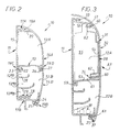
- a chute of the kind comprising, in a manner known per se, of a share, a base 11, the interior volume of which is fragmented into at least two compartments 12A, 12B by at least one partitioning wall 13, and, on the other hand, covers 14A, 14B each associated respectively with these compartments 12A, 12B, one per compartment 12A, 12B.
- the base 11 includes a bottom 15 flat, by which it is adapted to be applied to any wall 16, by example, and as shown, a wall at the base of which the chute 10 runs in baseboard.
- the base 11 further comprises along the longitudinal edges of this bottom 15, substantially perpendicular thereto, two lateral wings 17A, 17B.
- these lateral wings 17A, 17B are of very different heights.
- the side wing 17A which is the one which extends along the upper longitudinal edge of the bottom 15, at a height very significantly lower than that of the opposite side wing 17B.
- the upper compartment 12A is normally used for implantation any apparatus, and in particular any apparatus not shown.
- the lower compartment 12B is normally assigned to the installation of cables or conductors 18, in this case cables or electrical conductors, as shown in dashed lines in the figures 2, 3 and 33.
- latching means 19A, 19C To maintain the cover 14A of the upper compartment 12A, it is provided, between the base 11 and this cover 14A, latching means 19A, 19C.
- the latching means 19A intervene between the lateral wing 17A of the base 11 and a tongue 20 provided for this purpose projecting from the inner surface of the cover 14A.
- the latching means 19C intervene, them, between a console 22 provided for this purpose projecting from the bottom 15 of the base 11 and the bulkhead compartmentalization 13, the latter presenting in correspondence for this purpose to its base return 23.
- the latching means 19B intervene between the lateral wing 17B of the base 11 and a tongue 24 that the cover 14B projects for this purpose on its inner surface, the lateral wing 17B of the base 11 having itself, in correspondence, projecting from its outer surface, a console 25.
- the snap-fastening means 19D intervene between the bulkhead of compartmentalization 13 belonging to cover 14A of compartment 12A upper and a tongue 26 that the cover 14B has for this purpose projecting on its inner surface, parallel to its previous tongue 24, the partition compartmentalization 13 presenting itself, in correspondence, at its root, parallel to its return 23, a console 27.
- compartment 12B lower, or wiring compartment is itself subdivided into sub-compartments 12'B, 12 "B, 12" 'B by partitions 28, 29, which, coming from a integral with the bottom 15 of the base 11, extend parallel to each other, at distance from each other, and whose heights, all less than the height of the lateral wing 17B of this base 11, are themselves different from each other, the height of the partition 28 furthest from the lateral wing 17B being less than the height of the partition 29 closest to the latter.
- the chute 10 is equipped with at least one accessory A1, A'1, A2, A'2 ... etc ..., which extends transversely to its compartments 12A, 12B, and which comprises, in the form of parts separate, a body 31, 31 'and a cover 32, 32' with, and according to provisions described in more detail later, on the body 31, 31 ′, means engagement 33 by which this accessory A1, A'1, A2, A'2 ... etc ... is suitable for be secured to the base 11 of the chute 10, and, between the body 31, 31 'and the cover 32, 32 ', latching means 34 by which the cover 32, 32' is adapted to be attached to the body 31, 31 '.
- the chute 10 when, as shown in Figures 1 to 20, the chute 10 is implanted on walls 16, 16 ′ forming a dihedral of edge D between them, by successively presenting for this purpose trough sections 10, 10 ′ of different orientations, at the rate of a section of chute 10, 10 ′ per wall 16, 16 ', provision is made for the connection of these trunking sections 10, 10', two corner accessories A1 (or A2), A'1 (or A'2), due to an angle accessory A1 or A2, A'1 or A'2 per section of chute 10, 10 ', for the constitution of what is commonly called an angle 35.E, 35.1.
- the chute 10 is identified with one and / or the other of the trough sections 10, 10 'which constitute it.
- the angle 35.E is an external angle, that is to say a protruding, and it consists of angle accessories A1, A'1.
- the angle 35.1 is an internal angle, that is to say a re-entrant angle, and it consists of accessories of angle A2, A'2.
- the body 31, 31 'of an accessory A1, A'1, A2, A'2 ... etc ... generally equipping the chute 10 does not extend transversely than through a limited number of its compartments 12A, 12B, less than the total number of these.
- the interior volume of the base 11 of the chute 10 is fragmented into two compartments 12A, 12B, namely a installation compartment 12A used for the installation of any equipment, and a wiring compartment 12B dedicated to the installation of cables or conductors, the body 31, 31 'of the accessory A1, A'1, A2, A'2 ... etc ... does not extend transversely than through the installation compartment 12A.
- the cover 32, 32 'of this accessory A1, A'1, A2, A'2 ... etc ... preferably extends over all of these compartments 12A, 12B.
- the body 31, 31 'of an accessory A1, A'1, A2, A'2 ... etc ... fitted to the chute 10 is inserted between two cover sections 14A, 14'A 14B, 14'B of the compartment (s) 12A, 12B through which it extends, and its cover 32, 32 'covers these cover sections 14A, 14'A 14B, 14'B.
- the body 31, 31 ′ of such an accessory A1, A'1, A2, A'2 ... etc ... only extends through the single installation compartment 12A, it is inserted between two cover sections 14A, 14'A of the cover corresponding.
- the cover 32, 32 ′ covers, in continuity, both these cover sections 14A, 14'A as cover sections 14B, 14'B as a corollary closing of the wiring compartment 12B of the trunking sections 10, 10 ', the cover sections 14B, 14'B having in practice been cut to the same length as the cover sections 14A, 14'A.
- the body 31, 31 'of an accessory A1, A'1, A2, A'2 ... etc ... generally extends over a length less than that along which extends the cover 32, 32 'associated therewith.
- the cover 32, 32 ′ therefore generally extends overhang relative to the body 31.
- the cover 32, 32 ′ comprises, however, also, at a distance from the body 31, according to arrangements described more in detail later, engagement means 37 by which, for the strengthening of its hold, it is able to engage with the base 11 of the chute 10.
- an accessory of angle A1, A'1, A2, A'2, the body 31, 31 'of such an accessory of angle A1, A'1, A2, A'2 comprises, side by side, in the embodiment shown, on the one hand, a block 38, 38 ′ which is substantially rectilinear, and to which both the engagement means 33 allowing its attachment to the base 11 of the chute 10 as the latching means 34 allowing the fixing of the cover 32, 32 ' associated, and, on the other hand, a barrel 39, 39 'which is curved, in practice in an arc of a circle, and which is extended by a base 40, 40 ′ carrying at least one cross member 41, 41 ', 42, 42' 43, 43 'able to cover at least partially a cross member 41, 41', 42, 42 ', 43, 43' provided in correspondence for this purpose on the base 40, 40 'of the barrel 39, 39 'of the body 31, 31' of the corner accessory A1, A'1, A2, A'2 which is attached to
- Each of these crosspieces 41, 41 ', 42, 42', 43, 43 ' extends level with a side wing or a partition of the base 11 of the chute 10.
- three sleepers 41, 41 ', 42, 42', 43, 43 ' are provided.
- the cross member 41, 41 ′ extends flush with the lateral wing 17B of the base 11 of the chute 10, the cross-member 42, 42 ′ extends level with the partition 29 of the latter, and the crosspiece 43, 43 ′ extends level with its partition 28.
- each of the crosspieces 41, 41 ', 42, 42 ', 43, 43' extends in plan, substantially following a quarter of a circle, and has, in axial section, a square profile, being bordered, along its free edge, by a rim 44 which extends in the direction of the corresponding barrel 39, 39 ′.
- the base 40, 40 'of the shaft 39, 39 'of the corner accessories A1, A'1 also carries, transversely, consoles 46, 46 ', 47, 47', 48, 48 ', which, each associated respectively with sleepers 41, 41 ', 42, 42', 43, 43 ', extend in the opposite direction to them and are slightly offset axially in the direction of the barrel 39, 39 'relative to they.
- consoles 46, 46 ', 47, 47', 48, 48 ' have, in plan, an outline generally trapezoidal, and they have no edges.
- the block 38, 38 'of these corner accessories A1, A'1 has a longitudinal wall 50, through which it is attached to the associated barrel 39, 39 ′, coming in practice from molding a single part with this, two transverse walls 52, 53, one upper, the other lower, thanks to which the engagement means 33 intervene, and a front wall 54, the outline of which is generally rectangular, and thanks to which the snap-in means intervene 34.
- this block 38, 38 ' has, in further, parallel to its longitudinal wall 50, another longitudinal wall 55.
- the block 38, 38 ' On its longitudinal wall 55, the block 38, 38 'has, projecting, parallel to the front wall 54, and slightly set back from the latter, a tongue 56 intended to engage under the cover section 14A, 14'A corresponding.
- the barrels 39, 39 ' can overlap each other, one of these barrels 39, 39 ', in this case the barrel 39' of the corner accessory A'1, present, transversely, at a distance from each other, two slots 49 'allowing its nesting with an offset part 49 of the barrel 39 of the corner accessory A1.
- the block 38, 38 'of the body 31, 31 'of the corner accessories A1, A'1 has, locally, on the side opposite the base 40, 40 'of the barrel 39, 39' of this body 31, 31 ', a return 45 which extends from side of this barrel 39, 39 ′, substantially following the contour of the transverse wall 52 top of block 38, 38 '.
- the engagement means 33 for securing the corner accessories A1, A'1 to the base 11 of the chute 10 intervene at least partly by snap-fastening.
- they comprise a hook 57, which, projecting from the outer surface of the transverse wall 52 upper part of block 38, 38 'of body 31, 31' of these angle accessories A1, A'1, is intended to cooperate in latching with the lateral wing 17A of the base 11 of the chute 10, instead of the tongue 20 of the cover 14A thereof.
- transverse wall 52 upper of block 38, 38 ' is reinforced, perpendicular to the hook 57, by two stiffening ribs 58 (FIG. 8), which act on its outer surface, at a distance from each other, in its median zone, and which is square to hook 57.
- this hook 57 extends along the free edge of the wall transverse 52 upper block 38, 38 '.
- the engagement means 33 also have a tongue 59 which projects from the transverse wall 53 lower of the block 38, 38 ', on the outer surface thereof, and which is intended to cooperate in engagement with the console 22 of the base 11 of the chute 10, instead of the return 23 of the compartmentalization partition 13 of the corresponding cover 14A thereof.
- this tongue 59 extends along the free edge of the wall lower cross section 53 of block 38, 38 '.
- the engagement means 33 intervene, in part, by snap-fastening, by hook 57, and, in part, by simple engagement, by the tongue 59.
- the latching means 34 provided for reporting, on the body 31, 31 'of the angle accessories A1, A'1, the cover 32, 32' associated with this body 31, 31 ′ have, projecting from the inner surface of the cover 32, 32 ′, two snap tabs 60, spaced apart from one another, in parallel to each other, and, in correspondence, on the body 31, 31, two notches 61.
- these notches 61 are formed by the edge of chimneys 62 in which engage the latching tabs 60 of the cover 32, 32 '.
- the means engagement 37 also provided to strengthen the holding of the cover 32, 32 ' have a snap tab 63, which projects from the inner surface of this cover 32, 32 ′ parallel to the previous snap-on lugs 60, and by which this cover 32, 32 'is able to cooperate by snap-fastening with the console 25 of the base 11 of the chute 10, instead of the tongue 24 of the corresponding cover 14B.
- the latching tabs 60, 63 protrude from a part 64 cover 32, 32 ', which, intended to be superimposed on the front wall 54 of the block 38, 38 'of the corresponding body 31, 31', has substantially the same configuration that the latter, and only a portion 65 of this cover 32, 32 ′ is bent, adjacent to the previous.
- the angle accessories A2, A'2 of the interior angle 35.1 shown in the Figures 14 to 20 have constitutions substantially similar to those of corner accessories A1, A'1 previous.
- the cross member 41, 41 'corresponding to the lateral wing 17B of the base 11 of the chute 10 has no rim, and the rim 44 of the crosspieces 42, 42 '43, 43' each corresponding respectively to the partitions 28, 29 of this base 11 has a relatively accentuated height.
- the curved part 65 of their cover 32, 32 ' has, at its end upper, a return 66, for mutual covering of one of these covers 32, 32 'to each other, like crosspieces 41, 41', 42, 42 ', 43, 43, 43'.
- the accessory A3 fitted to the chute 10 is a seal cover.
- this accessory A3 is inserted between two cover sections 14A, 14'A of the compartment or compartments through from which it extends, in this case the only compartment 12A, and its cover 32 covers these cover sections 14A, 14'A.
- cover 14B of the wiring compartment 12B is itself split into two sections of cover 14B, 14'B, as before.
- this cover 14B can, if desired, run continuously, without such fractionation.
- the body 31 of the accessory A3 is able to receive this cover 14B.
- the corresponding cache 32 is in two parts, namely an upper part 32A, which corresponds to the installation compartment 12A, and which is the only one preserved when the cover 14B associated with the compartment of wiring 12B short continuous, and a lower part 32B, which corresponds to this wiring compartment 12B, and which is also retained when, as shown, the corresponding cover 14B is divided into two sections of cover 14B, 14'B.
- the body 31 of the accessory A3 is itself in at least two parts 31a, 31b, 31c, which are staggered transversely across the width of the compartment concerned, in this case the installation compartment 12A, and which are duly secured to one another.
- this body 31 is in three parts 31a, 31b, 31c, namely, an upper part 31a, an intermediate part 31b, and a lower part 31c.
- the upper part 31a comprises, on the one hand, the hook 57 intended to cooperate in latching with the lateral wing 17A of the base 11 of the chute 10, and, on the other hand, a chimney 62 intended to allow the latching of the cover 32, and, more precisely, that of the upper part 32A of this cover 32.
- the lower part 31c of the body 31 comprises, on the one hand, the tongue 59 intended to come into engagement with the console 22 of the base 11 of the chute 10, and, on the other hand, another chimney 62.
- the upper part 32A of the cover 32 has, projecting from its inner surface, and correspondence, each respectively, with the two chimneys 62 and the opening 62 ', three latching tabs 60, instead of two as previously.
- the upper part 31a of the body 31 and its intermediate part 31b interlocking means intervene the upper part 31a comprising a chimney 69 able to forcibly receive a pin 70 projecting for this purpose on the upper surface of a plate 71 by which the intermediate part 31b is able to engage under the corresponding end of this upper part 31a.
- the chimney 69 has, in section transverse, an elongated contour longitudinally in the buttonhole, following the width of the upper part 31a and of the intermediate part 31b, and so on the same for pawn 70.
- this notch 73 is formed by one of the edges of an opening 74 perforating the plate 71 of the intermediate part 31b, parallel to the pin 70, and at a distance therefrom.
- engagement means and latching means of the same type as the previous ones intervene between the intermediate part 31b and the lower part 31c of the body 31.
- the intermediate part 31b also includes a chimney 69 and a latching tab 72, and, in correspondence, the part lower 31c comprises, on a plate 71, a pin 70 and an opening 74 of which one of the edges forms a notch 73.
- the upper part 31a of the body 31 can indifferently be coupled with the intermediate part 31b or with the lower part 31c, and, from even, its lower part 31c can indifferently be coupled with the part intermediate 31b or the upper part 31a.
- the intermediate part 31b is, or no, implementation, along the width of the chute 10.
- the accessory A3 also comprises, in addition to its body 31, or body main body, and aligned with it, another body 75, or auxiliary body, which extends through at least one of the compartments contiguous to that through from which the main body 31 extends, and which, like this one, comprises engagement means 77 by which it is able to be secured to the base 11 of the chute 10.
- the body 31 extending through the compartment installation 12A, the auxiliary body 75 extends through the single compartment 12B wiring.
- the engagement means 77 comprise, at the upper end of the auxiliary body 75, a groove 78, which extends longitudinally, along its corresponding transverse edge, and by which it is able to engage with the console 68 that comprises the main body 31, thus being secured to the base 11 of the chute 10 through the latter.
- the engagement means 77 also include, in the form of embodiment shown, at the lower end of the auxiliary body 75, projecting on its inner surface, at least one tongue 79 able to cooperate in latching with the console 25 of the base 11 of the chute 10, in the manner of tab 24 of cover 14B associated with wiring compartment 12B of this one.
- two tabs 79 are provided, at distance from each other, and in alignment with each other.
- auxiliary body 75 extends, in a bridge, to the part top of wiring compartment 12B, without significantly encroaching on the useful volume of it.
- the upper part 32A of the cover 32 corresponds to the single main body 31, and its lower part 32B to the single auxiliary body 75.
- the auxiliary body 75 also includes chimneys 62 or opening 62 ', for cooperation with latching tabs 60 provided for therein effect on the lower part 32B of the cover 32.
- auxiliary body 75 it is possible to arrange the auxiliary body 75 elsewhere than in the alignment of the body 31, for example if one wishes to shift the parts 32A and 32B of the cover 32.
- an auxiliary body is not used 75 and we replace the cover 32 in two parts 32A and 32B with a cover of a single holding it fixed on the body 31 and on the lateral wing 17B of the base 11.
- the accessory A4 equipping the chute 10 is an accessory passage, suitable for allowing either cable or conductor 18 circulating in the wiring compartment 12B to be introduced locally in the installation compartment 12A.
- the body 31 of this accessory A4 has at least one longitudinal wall 80, through which it is suitable for locally replacing the partitioning wall 13, and which is perforated by at least one passage 81, for the crossing sought for one or multiple cables or conductors 18.
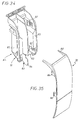
- Figures 34 and 35 are shown, on the one hand, the body 31 of a accessory A5 intended to form a derivation, and, on the other hand, the cover 32 to report on this body 31.
- an internal wall 84 is provided, and this extends parallel to the side walls 85 of the body 31, at mid-distance from these.
- the channels 83 allow one or more of the cables or conductors 18 to be derived from the compartment 12B wiring and lead laterally to the upper side of the installation compartment 12A, where they can then be taken up, so that traditional, by another chute, not shown, commonly known bypass chute, arranged for example in T with respect to the chute 10, so-called main chute.
- the cover 32 comprises, along of each of its lateral edges, two latching tabs 86 for cooperation with notches 87 provided in correspondence projecting from the inner surface of the side walls 85 of the body 31.
- This cover 32 also has, at its upper end, a opening 88, to allow the effective exit of one or more cables or conductors 18.
- this opening 88 can be partially obscured by knock-off lids to adjust the height and / or width depending on the corresponding bypass chute.
Landscapes
- Engineering & Computer Science (AREA)
- Architecture (AREA)
- Civil Engineering (AREA)
- Structural Engineering (AREA)
- Details Of Rigid Or Semi-Rigid Containers (AREA)
- Details Of Indoor Wiring (AREA)
Abstract
Description
- la figure 1 est une vue en perspective d'une goulotte suivant l'invention lorsque les deux accessoires qui l'équipent sont des accessoires d'angle assurant la constitution d'un angle extérieur ;
- les figures 2 et 3 sont des vues en coupe transversale de cette goulotte suivant, chacune respectivement, les lignes Il-Il et III-III de la figure 1 ;
- la figure 4 est une autre vue en perspective de la goulotte suivant l'invention, après enlèvement de ses couvercles et des caches des deux accessoires d'angle qui l'équipent ;
- la figure 5 est une vue en perspective du corps d'un de ces accessoires d'angle, représenté isolément, et vu de l'avant ;
- la figure 6 est une autre vue en perspective de ce corps, vu de l'arrière ;
- la figure 7 en est une vue en coupe, suivant la ligne VII-VII de la figure 5 ;
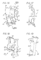
- la figure 8 en est, à échelle supérieure, et de manière partielle, une autre vue en coupe, suivant la ligne VIII-VIII de la figure 5 ;
- la figure 9 est une vue en perspective du corps de l'autre des accessoires d'angle concernés ;
- la figure 10 est une vue en coupe de ce corps, suivant la ligne X-X de la figure 9 ;
- la figure 11 en est, à échelle supérieure, une autre vue en coupe, suivant la ligne XI-XI de la figure 9 ;
- la figure 12 est une vue en perspective, et vu de l'arrière, du cache associé au corps représenté sur la figure 5 ;
- la figure 13 est, de manière semblable, une vue en perspective du cache associé au corps représenté sur la figure 9 ;
- la figure 14 est une vue en perspective d'une goulotte suivant l'invention lorsque les deux accessoires qui l'équipent sont des accessoires d'angle assurant la constitution d'un angle intérieur ;
- la figure 15 est une autre vue en perspective de cette goulotte lorsque, comme sur la figure 4, les couvercles de la goulotte et les caches de deux accessoires d'angle qui l'équipent ont été enlevés ;
- la figure 16 est une vue en perspective du corps d'un de ces accessoires d'angle, représenté isolément, et vu de l'avant ;
- la figure 17 est une vue en coupe de ce corps, suivant la ligne XVII-XVII de la figure 16 ;
- la figure 18 est une vue en perspective du corps de l'autre des accessoires d'angle concernés, vu de l'avant ;
- la figure 19 est une vue en perspective, et vu de l'arrière, du cache associé au corps représenté sur la figure 16 ;
- la figure 20 est une vue en perspective, et également vu de l'arrière, du cache associé au corps représenté sur la figure 18 ;
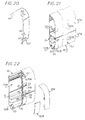
- la figure 21 est une vue en perspective d'une goulotte suivant l'invention lorsque l'accessoire qui l'équipe est un joint de couvercle ;
- la figure 22 est une autre vue en perspective de cette goulotte lorsque, comme sur les figures 4 et 15, le cache correspondant, ici en deux parties, a été enlevé, et qu'il en a été de même pour ses couvercles sur l'un de ses tronçons ;
- la figure 23 est une vue en perspective d'une des parties constitutives du corps principal de l'accessoire en cause, vue de l'avant ;
- la figure 24 est une autre vue en perspective de cette partie de ce corps, vue de l'arrière ;
- les figures 25 et 26 sont des vues en perspective qui, correspondant chacune respectivement aux figures 23 et 24, se rapportent à une deuxième partie du corps de cet accessoire ;
- les figures 27 et 28 sont des vues en perspective qui, correspondant, elles aussi, chacune respectivement, aux figures 23 et 24, se rapportent à une troisième partie de ce corps ;
- la figure 29 est une vue en perspective d'un corps auxiliaire que comporte, en l'espèce, l'accessoire en cause, vu de l'avant ;
- la figure 30 est une autre vue en perspective de ce corps auxiliaire, vu de l'arrière ;
- la figure 31 est une vue en perspective d'une des parties constitutives du cache de l'accessoire en cause, vue de l'arrière ;
- la figure 32 est une vue en perspective de l'autre des parties constitutives de ce cache, également vue de l'arrière ;
- la figure 33 est une vue en coupe transversale d'une goulotte suivant l'invention lorsque l'accessoire qui l'équipe est un accessoire de passage ;
- la figure 34 est une vue en perspective d'un accessoire de dérivation susceptible d'équiper également une goulotte suivant l'invention, vu de l'avant ;
- la figure 35 est une vue en perspective du cache alors associé à un tel accessoire de dérivation, vu de l'avant.
Claims (24)
- Goulotte, qui, d'une part, est du genre comportant un socle (11) dont le volume intérieur est fragmenté en au moins deux compartiments (12A, 12B) séparés l'un de l'autre par au moins une cloison de compartimentage (13) et des couvercles (14A, 14B) associés chacun respectivement à ces compartiments (12A, 12B), et qui, d'autre part, est équipée d'au moins un accessoires (A1, A'1, A2, A'2 ... etc...) qui s'étend transversalement par rapport à ses compartiments (12A, 12B) et qui comporte, sous la forme de pièces distinctes, un corps (31, 31') et un cache (32, 32'), avec, sur le corps (31, 31'), des moyens d'engagement (33) par lesquels cet accessoire (A1, A'1, A2, A'2 ... etc...) est apte à être solidarisé au socle (11) de la goulotte (10), et, entre le corps (31, 31') et le cache (32, 32'), des moyens d'encliquetage (34) par lesquels le cache (32, 32') est apte à être rapporté sur le corps (31, 31'), caractérisée en ce que le corps (31, 31') de l'accessoire (A1, A1, A2, A'2 ... etc...) ne s'étend transversalement qu'à travers un nombre limité de compartiments (12A, 12B) sur une longueur inférieure à celle suivant laquelle s'étend son cache.
- Goulotte suivant la revendication 1, caractérisée en ce que, le volume intérieur du socle (il) étant fragmenté en deux compartiments (12A, 12B), à savoir un compartiment d'installation (12A) dévolu à l'implantation d'éventuels appareillages, et un compartiment de câblage (12B) dévolu à l'implantation de câbles ou de conducteurs (18), le corps (31, 31') de l'accessoire (A1, A'1, A2, A'2 ... etc...) ne s'étend transversalement qu'à travers le compartiment d'installation (12A).
- Goulotte suivant l'une quelconque des revendications 1, 2, caractérisée en ce que le cache (32, 32') de l'accessoire (A1, A'1, A2, A'2 ... etc...) s'étend sur la totalité de ses compartiments (12A, 12B).
- Goulotte suivant l'une quelconque des revendications 1 à 3, caractérisée en ce que le corps (31, 31') de l'accessoire (A1, A'1, A2, A'2 ... etc...) est inséré entre deux tronçons de couvercle (14A, 14'A) associés au ou aux compartiments au travers du ou desquels il s'étend, et son cache (32, 32') recouvre ces tronçons de couvercle (14A, 14'A).
- Goulotte suivant l'une quelconque des revendications 1 à 4, caractérisée en ce que la cloison de compartimentage (13) appartenant à l'un des couvercles (14A, 14B), le corps (31) de l'accessoire (A4) comporte au moins une paroi longitudinale (80), par laquelle il est apte à se substituer localement à cette cloison de compartimentage (13), et qui est ajourée par au moins un passage (81).
- Goulotte suivant l'une quelconque des revendications 1 à 5, caractérisée en ce que le corps (31, 31') de l'accessoire (A1, A'1, A2, A'2 ... etc...) est apte à recevoir le couvercle (14B) associé au ou aux compartiments (12B) contigus de celui ou de ceux au travers du ou desquels ils s'étend.
- Goulotte suivant l'une quelconque des revendications 1 à 6, caractérisée en ce que, l'accessoire (A3) étant un joint de couvercle, son corps (31) est en au moins deux parties (31a, 31b, 31c), qui sont échelonnées transversalement sur la largeur du ou des compartiments (12A) concernés, et qui sont solidarisées l'une à l'autre.
- Goulotte suivant la revendication 7, caractérisée en ce que l'accessoire (A3) comporte également un corps auxiliaire (75), qui s'étend au travers d'au moins un compartiment contigu de celui ou de ceux au travers du ou desquels s'étend son premier corps (31) ou corps principal, et qui, comme celui-ci, comporte des moyens d'engagement (77) par lesquels il est apte à être solidarisé au socle (11).
- Goulotte suivant la revendication 8, caractérisée en ce que le corps auxiliaire (75) de l'accessoire (A3) est aligné avec son corps principal (31).
- Goulotte suivant l'une quelconque des revendications 1 à 6, caractérisée en ce que, l'accessoire (A4) étant un accessoire de passage, son corps (31) comporte au moins une paroi longitudinale (80) par laquelle il est apte à se substituer localement à la cloison de compartimentage (13), et qui est ajourée par au moins un passage (81).
- Goulotte suivant l'une quelconque des revendications 1 à 6, caractérisée en ce que, l'accessoire (A5) étant un accessoire de dérivation, son corps (31) est fragmenté intérieurement, transversalement par rapport à la goulotte, en au moins deux rigoles (83), par au moins une paroi interne (84).
- Goulotte suivant l'une quelconque des revendications 1 à 11, caractérisée en ce que le cache (32) de l'accessoire (A1, A'1, A2, A'2 ... etc...) est en deux parties (32A, 32B).
- Accessoire pour l'équipement d'une goulotte (10) du genre comportant au moins un corps (31, 31'), par lequel il est apte à être solidarisé au socle (11) de cette goulotte (10), et au moins un cache (32, 32'), qui est apte à être rapporté sur le corps (31, 31'), caractérisé en ce que, pour l'équipement d'une goulotte (10) conforme à l'une quelconque des revendications 1 à 12, le corps (31, 31') s'étend sur une longueur inférieure à celle suivant laquelle s'étend le cache (32, 32').
- Accessoire suivant la revendication 13, caractérisé en ce que le cache (32, 32') comporte, aussi, à distance du corps (31, 31'), des moyens d'engagement (37) par lesquels il est apte à venir en prise avec le socle (11) de la goulotte (10).
- Accessoire suivant l'une quelconque des revendications 13, 14, caractérisé en ce que, s'agissant d'un accessoire d'angle (A1, A'1, A2, A'2), le corps (31, 31') comporte, côte à côte, un bloc (38, 38'), qui est sensiblement rectiligne, et auquel appartiennent tant les moyens d'engagement (33) que les moyens d'encliquetage (34), et un fût (39, 39'), qui est cintré, et qui se prolonge par un piétement (40, 40') porteur d'au moins une traverse (41, 41', 42, 42', 43, 43') apte à recouvrir au moins en partie une traverse (41, 41', 42, 42', 43, 43') prévue en correspondance à cet effet sur le piétement (40, 40') du fût (39, 39') de l'accessoire d'angle (A1, A'1, A2, A'2) associé.
- Accessoire suivant la revendication 15, caractérisé en ce que la traverse (41, 41', 42, 42', 43, 43') a, en section axiale, un profil en équerre.
- Accessoire suivant l'une quelconque des revendications 15, 16, caractérisé en ce que s'agissant d'un accessoire d'angle (A2, A'2) pour angle (35.1) intérieur, la traverse (41, 41', 42, 42', 43, 43') se prolonge à l'aplomb du bloc (38, 38').
- Accessoire suivant l'une quelconque des revendications 15 à 17, caractérisé en ce que la traverse (41, 41', 42, 42', 43, 43') s'étend à niveau avec une aile latérale (17B) ou une cloison (28, 29) du socle (11) de la goulotte (10).
- Accessoire suivant l'une quelconque des revendications 15 à 18, caractérisé en ce qu'il y a, échelonnées en hauteur le long du piétement (40, 40'), plusieurs traverses (41, 41', 42, 42', 43, 43').
- Accessoire suivant la revendication 13, caractérisé en ce que, s'agissant d'un joint de couvercle, le corps (31) est en au moins deux parties (31 a, 31b, 31c) aptes à être successivement solidarisées l'une à l'autre.
- Accessoire suivant la revendication 20, caractérisé en ce qu'il comporte, en sus de son corps (31), ou corps principal, et aligné avec celui-ci, un autre corps (75), ou corps auxiliaire.
- Accessoire suivant la revendication 13, caractérisé en ce que, s'agissant d'un accessoire de passage, le corps (31) comporte au moins une paroi longitudinale (80) ajourée par au moins un passage (81).
- Accessoire suivant la revendication 13, caractérisé en ce que, s'agissant d'un accessoire de dérivation, le corps (31) est fragmenté intérieurement en au moins deux rigoles (83) par au moins une paroi interne (84).
- Accessoire suivant l'une quelconque des revendications 13 à 23, caractérisé en ce que le cache (32, 32') est en deux parties (32A, 32B).
Applications Claiming Priority (2)
| Application Number | Priority Date | Filing Date | Title |
|---|---|---|---|
| FR9912964A FR2799899B1 (fr) | 1999-10-18 | 1999-10-18 | Goulotte equipee d'au moins un accessoire, et accessoires correspondants, notamment pour appareillages electriques |
| FR9912964 | 1999-10-18 |
Publications (2)
| Publication Number | Publication Date |
|---|---|
| EP1094580A1 true EP1094580A1 (fr) | 2001-04-25 |
| EP1094580B1 EP1094580B1 (fr) | 2011-09-28 |
Family
ID=9551047
Family Applications (1)
| Application Number | Title | Priority Date | Filing Date |
|---|---|---|---|
| EP20000402741 Expired - Lifetime EP1094580B1 (fr) | 1999-10-18 | 2000-10-05 | Goulotte équipée d'au moins un accessoire, et accessoires correspondants, notamment pour appareillages électriques |
Country Status (3)
| Country | Link |
|---|---|
| EP (1) | EP1094580B1 (fr) |
| ES (1) | ES2374060T3 (fr) |
| FR (1) | FR2799899B1 (fr) |
Cited By (1)
| Publication number | Priority date | Publication date | Assignee | Title |
|---|---|---|---|---|
| EP1241759A1 (fr) * | 2001-03-16 | 2002-09-18 | Tehalit GmbH & Co. KG | Pièce formée pour joindre deux ou plus tronçons de conduite de câbles disposés selon un angle |
Citations (5)
| Publication number | Priority date | Publication date | Assignee | Title |
|---|---|---|---|---|
| GB932453A (en) * | 1958-12-08 | 1963-07-24 | Walsall Conduits Ltd | Improvements relating to trunking for electrical wiring systems |
| DE7836010U1 (de) * | 1978-12-05 | 1979-03-15 | Fa. Albert Ackermann, 5270 Gummersbach | Sockelleistenkanal für Elektroinstallationen |
| GB2174254A (en) * | 1985-04-11 | 1986-10-29 | Ega Ltd | Trunking system component |
| FR2731496A1 (fr) | 1995-03-09 | 1996-09-13 | Planet Wattohm Sa | Dispositif de raccordement d'angle pour conduit a corps en gouttiere et couvercle tel que moulure, plinthe ou goulotte, notamment pour appareillage electrique |
| FR2772200A1 (fr) | 1997-12-04 | 1999-06-11 | Legrand Sa | Accessoire de cheminement pour goulotte, tel que angle ou derivation |
-
1999
- 1999-10-18 FR FR9912964A patent/FR2799899B1/fr not_active Expired - Fee Related
-
2000
- 2000-10-05 ES ES00402741T patent/ES2374060T3/es not_active Expired - Lifetime
- 2000-10-05 EP EP20000402741 patent/EP1094580B1/fr not_active Expired - Lifetime
Patent Citations (5)
| Publication number | Priority date | Publication date | Assignee | Title |
|---|---|---|---|---|
| GB932453A (en) * | 1958-12-08 | 1963-07-24 | Walsall Conduits Ltd | Improvements relating to trunking for electrical wiring systems |
| DE7836010U1 (de) * | 1978-12-05 | 1979-03-15 | Fa. Albert Ackermann, 5270 Gummersbach | Sockelleistenkanal für Elektroinstallationen |
| GB2174254A (en) * | 1985-04-11 | 1986-10-29 | Ega Ltd | Trunking system component |
| FR2731496A1 (fr) | 1995-03-09 | 1996-09-13 | Planet Wattohm Sa | Dispositif de raccordement d'angle pour conduit a corps en gouttiere et couvercle tel que moulure, plinthe ou goulotte, notamment pour appareillage electrique |
| FR2772200A1 (fr) | 1997-12-04 | 1999-06-11 | Legrand Sa | Accessoire de cheminement pour goulotte, tel que angle ou derivation |
Cited By (1)
| Publication number | Priority date | Publication date | Assignee | Title |
|---|---|---|---|---|
| EP1241759A1 (fr) * | 2001-03-16 | 2002-09-18 | Tehalit GmbH & Co. KG | Pièce formée pour joindre deux ou plus tronçons de conduite de câbles disposés selon un angle |
Also Published As
| Publication number | Publication date |
|---|---|
| ES2374060T3 (es) | 2012-02-13 |
| EP1094580B1 (fr) | 2011-09-28 |
| FR2799899A1 (fr) | 2001-04-20 |
| FR2799899B1 (fr) | 2002-01-04 |
Similar Documents
| Publication | Publication Date | Title |
|---|---|---|
| EP0382597B1 (fr) | Profilé, tel que goulotte, plinthe, moulure ou autre, pour le logement et la protection, en particulier, d'appareillages électriques et des conducteurs nécessaires à la desserte de ceux-ci | |
| EP0149377B1 (fr) | Goulotte composite, à élément(s) rapporté(s), notamment pour logement de câbles électriques | |
| EP1094578B1 (fr) | Agrafe de retenue pour goulotte, notamment pour appareillages électriques | |
| EP1119088B1 (fr) | Conduit de câblage électrique à multicompartiments présentant une grande capacité de câblage | |
| EP0776079A1 (fr) | Dispositif de support pour appareillage, en particulier pour appareillage électrique, à rapporter sur un corps de goulotte | |
| EP1094581B1 (fr) | Accessoire de passage pour goulotte | |
| EP0986849B1 (fr) | Goulotte de cablage et accessoire susceptible d' etre rapporte sur une telle goulotte de cablage | |
| EP1042851B1 (fr) | Accessoire d'angle a angle variable pour goulotte | |
| EP1149447B1 (fr) | Support d'appareillage, notamment pour appareillage electrique, et boitier comportant un tel support d'appareillage | |
| EP1094580B1 (fr) | Goulotte équipée d'au moins un accessoire, et accessoires correspondants, notamment pour appareillages électriques | |
| FR2758016A1 (fr) | Procede et dispositif pour affermir le maintien sur une goulotte d'un quelconque accessoire a rapporter par emboitement sur le socle de celle-ci | |
| FR2772200A1 (fr) | Accessoire de cheminement pour goulotte, tel que angle ou derivation | |
| EP0440556B1 (fr) | Boîte d'encastrement à prolongement latéral, notamment pour appareil électrique | |
| EP0792532B1 (fr) | Embout pour goulotte de cheminement de conducteurs electriques | |
| EP1164676B1 (fr) | Dispositif de montage d'un appareil électrique sur un conduit de câblage | |
| BE1013053A3 (fr) | Boite d'encastrement susceptible d'etre jumelee avec un autre, notamment pour appareillage electrique. | |
| EP0786845A1 (fr) | Gaine, notamment pour établissement hospitalier | |
| EP0267079A1 (fr) | Accessoire de dérivation pour conduit de câblage | |
| EP1211773B1 (fr) | Support pour appareillage, en particulier pour appareillage électrique, à rapporter sur le socle d'une goulotte | |
| EP0964494B1 (fr) | Accessoire de dérivation pour installation électrique, et installation électrique correspondante | |
| EP1351359A1 (fr) | Support d'appareillage pour goulotte avec accès aux bornes de connexion électrique | |
| FR2715795A1 (fr) | Boîte pour le logement d'un appareillage électrique dans une goulotte. | |
| FR2765739A1 (fr) | Goulotte et accessoire correspondant | |
| FR2732089A1 (fr) | Accessoire pour goulotte, notamment pour conducteurs electriques | |
| FR2786946A1 (fr) | Accessoire de derivation a disposer a la jonction d'au moins deux goulottes |
Legal Events
| Date | Code | Title | Description |
|---|---|---|---|
| PUAI | Public reference made under article 153(3) epc to a published international application that has entered the european phase |
Free format text: ORIGINAL CODE: 0009012 |
|
| AK | Designated contracting states |
Kind code of ref document: A1 Designated state(s): DE ES GB IT SE |
|
| AX | Request for extension of the european patent |
Free format text: AL;LT;LV;MK;RO;SI |
|
| 17P | Request for examination filed |
Effective date: 20010329 |
|
| AKX | Designation fees paid |
Free format text: DE ES GB IT SE |
|
| RAP1 | Party data changed (applicant data changed or rights of an application transferred) |
Owner name: LEGRAND FRANCE Owner name: LEGRAND SNC |
|
| 17Q | First examination report despatched |
Effective date: 20081121 |
|
| GRAP | Despatch of communication of intention to grant a patent |
Free format text: ORIGINAL CODE: EPIDOSNIGR1 |
|
| GRAC | Information related to communication of intention to grant a patent modified |
Free format text: ORIGINAL CODE: EPIDOSCIGR1 |
|
| RTI1 | Title (correction) |
Free format text: CHANNEL WITH AT LEAST AN ACCESSORY AND CORRESPONDING ACCESSORY, FOR AN ELECTRICAL APPARATUS |
|
| GRAS | Grant fee paid |
Free format text: ORIGINAL CODE: EPIDOSNIGR3 |
|
| GRAA | (expected) grant |
Free format text: ORIGINAL CODE: 0009210 |
|
| AK | Designated contracting states |
Kind code of ref document: B1 Designated state(s): DE ES GB IT SE |
|
| REG | Reference to a national code |
Ref country code: GB Ref legal event code: FG4D Free format text: NOT ENGLISH |
|
| REG | Reference to a national code |
Ref country code: DE Ref legal event code: R096 Ref document number: 60046477 Country of ref document: DE Effective date: 20111124 |
|
| PG25 | Lapsed in a contracting state [announced via postgrant information from national office to epo] |
Ref country code: SE Free format text: LAPSE BECAUSE OF FAILURE TO SUBMIT A TRANSLATION OF THE DESCRIPTION OR TO PAY THE FEE WITHIN THE PRESCRIBED TIME-LIMIT Effective date: 20110928 |
|
| REG | Reference to a national code |
Ref country code: ES Ref legal event code: FG2A Ref document number: 2374060 Country of ref document: ES Kind code of ref document: T3 Effective date: 20120213 |
|
| PLBE | No opposition filed within time limit |
Free format text: ORIGINAL CODE: 0009261 |
|
| STAA | Information on the status of an ep patent application or granted ep patent |
Free format text: STATUS: NO OPPOSITION FILED WITHIN TIME LIMIT |
|
| GBPC | Gb: european patent ceased through non-payment of renewal fee |
Effective date: 20111228 |
|
| 26N | No opposition filed |
Effective date: 20120629 |
|
| REG | Reference to a national code |
Ref country code: DE Ref legal event code: R097 Ref document number: 60046477 Country of ref document: DE Effective date: 20120629 |
|
| PG25 | Lapsed in a contracting state [announced via postgrant information from national office to epo] |
Ref country code: GB Free format text: LAPSE BECAUSE OF NON-PAYMENT OF DUE FEES Effective date: 20111228 |
|
| PGFP | Annual fee paid to national office [announced via postgrant information from national office to epo] |
Ref country code: ES Payment date: 20120919 Year of fee payment: 13 |
|
| PGFP | Annual fee paid to national office [announced via postgrant information from national office to epo] |
Ref country code: DE Payment date: 20121029 Year of fee payment: 13 |
|
| PGFP | Annual fee paid to national office [announced via postgrant information from national office to epo] |
Ref country code: IT Payment date: 20121025 Year of fee payment: 13 |
|
| REG | Reference to a national code |
Ref country code: DE Ref legal event code: R119 Ref document number: 60046477 Country of ref document: DE Effective date: 20140501 |
|
| PG25 | Lapsed in a contracting state [announced via postgrant information from national office to epo] |
Ref country code: IT Free format text: LAPSE BECAUSE OF NON-PAYMENT OF DUE FEES Effective date: 20131005 Ref country code: DE Free format text: LAPSE BECAUSE OF NON-PAYMENT OF DUE FEES Effective date: 20140501 |
|
| REG | Reference to a national code |
Ref country code: ES Ref legal event code: FD2A Effective date: 20141107 |
|
| PG25 | Lapsed in a contracting state [announced via postgrant information from national office to epo] |
Ref country code: ES Free format text: LAPSE BECAUSE OF NON-PAYMENT OF DUE FEES Effective date: 20131006 |