EP1094456A2 - Disk device and guide member - Google Patents
Disk device and guide member Download PDFInfo
- Publication number
- EP1094456A2 EP1094456A2 EP00122036A EP00122036A EP1094456A2 EP 1094456 A2 EP1094456 A2 EP 1094456A2 EP 00122036 A EP00122036 A EP 00122036A EP 00122036 A EP00122036 A EP 00122036A EP 1094456 A2 EP1094456 A2 EP 1094456A2
- Authority
- EP
- European Patent Office
- Prior art keywords
- disk
- guide member
- tray
- depression
- disk tray
- Prior art date
- Legal status (The legal status is an assumption and is not a legal conclusion. Google has not performed a legal analysis and makes no representation as to the accuracy of the status listed.)
- Withdrawn
Links
- 210000000078 claw Anatomy 0.000 claims abstract description 40
- 230000002093 peripheral effect Effects 0.000 claims 2
- 230000001154 acute effect Effects 0.000 claims 1
- 230000003287 optical effect Effects 0.000 abstract description 46
- 238000010276 construction Methods 0.000 description 3
- 238000000034 method Methods 0.000 description 3
- 229920006324 polyoxymethylene Polymers 0.000 description 3
- 230000004308 accommodation Effects 0.000 description 2
- 229930040373 Paraformaldehyde Natural products 0.000 description 1
- 229930182556 Polyacetal Natural products 0.000 description 1
- 230000009286 beneficial effect Effects 0.000 description 1
- 238000004519 manufacturing process Methods 0.000 description 1
- 239000000463 material Substances 0.000 description 1
- -1 polyoxymethylene Polymers 0.000 description 1
- 210000000707 wrist Anatomy 0.000 description 1
Images



Classifications
-
- G—PHYSICS
- G11—INFORMATION STORAGE
- G11B—INFORMATION STORAGE BASED ON RELATIVE MOVEMENT BETWEEN RECORD CARRIER AND TRANSDUCER
- G11B17/00—Guiding record carriers not specifically of filamentary or web form, or of supports therefor
- G11B17/02—Details
- G11B17/04—Feeding or guiding single record carrier to or from transducer unit
- G11B17/05—Feeding or guiding single record carrier to or from transducer unit specially adapted for discs not contained within cartridges
- G11B17/053—Indirect insertion, i.e. with external loading means
- G11B17/056—Indirect insertion, i.e. with external loading means with sliding loading means
Definitions
- This invention concerns a disk device having a disk tray with a depression into which a disk for recording and/or playback is inserted and by which said disk is loaded into the device main body, and a guide member provided on said disk device for holding said disk in position on said disk tray.
- disk devices for CD, DVD, and other optical disk drives, etc. are disk devices in which an optical disk, which is an information recording medium, is inserted into a depression in a disk tray placed approximately horizontally, and said optical disk is loaded by accommodating the disk tray inside the device main body.
- an optical disk which is an information recording medium
- the aforesaid disk device besides being used in the horizontal orientation, in which the disk tray is horizontal, is also sometimes used in the vertical orientation, in which the disk tray is vertical. If the disk device is oriented vertically, it is not possible, just by inserting an optical disk into the depression, to hold the optical disk in the disk tray. Therefore, as disclosed in Japanese unexamined patent H6-251479 [1994], a disk device has been proposed that has a disk tray equipped with claws for holding the optical disk loosely clamped against the external circumference of the depression from outside its surface.
- a disk device that has a disk tray having a circular depression into which a disk is inserted and by which said disk is loaded into a device main body, and is characterized in that claws that can support part of the external circumference of the disk are provided on the external circumference of the depression, and a guide member that guides the disk between the depression and the claws is removably attached to the disk tray.
- said disk when a disk is to be mounted into the disk device in the vertical orientation, said disk can be automatically guided between the depression and the claws by moving the disk along the guide member. This eliminates the inconvenience of disk mounting caused by the vertical orientation of the disk device and facilitates the operation of mounting the disk into the disk tray.
- the guide member is detachable, it can be removed if it is to be used in horizontal orientation, in which case the operation of mounting a disk is made easy regardless of the orientation of the disk device.
- a disk tray having a depression into which a disk is inserted and, on the external circumference of the depression, claws that can support part of the external circumference of the disk, and a guide member having a guide surface that is continuous with the disk-facing disk support surface of said claws for guiding the disk between the depression and the claws, said guide member being formed detachably with respect to said disk tray.
- the guide member be constructed so as to grasp the claws of the disk tray from both sides. It is also preferable if the guide member is constructed so as to be detachable on the claws of the disk tray, so there will be no need for any special manufacturing or processing to attach and detach the guide member to and from the disk device. Thus it becomes possible to easily apply the guide member to any general-purpose disk device for guiding and holding a disk used therewith.
- Disk device 1 which plays back a CD-ROM, DVD-ROM, or other type of disk 2, comprises a device main body 10, inside which an optical pickup unit (not shown) is accommodated, and a disk tray 20, by which optical disk 2 is loaded into the device main body 10.
- Device main body 10 has outer case 11, in which is formed opening 11A for putting in and taking out disk tray 20, a spindle motor (not shown) and chucking pulley (not shown) that cause optical disk 2 placed in disk tray 20 to rotate, and an optical pickup unit that reads the information recorded on optical disk 2.
- disk tray 20 Formed on the surface of disk tray 20 are circular depressions 21, 22 into which optical disk 2 is inserted; of these, depression 21 corresponds to a 12 cm diameter disk, and depression 22 corresponds to an 8 cm diameter disk. Formed approximately in the center part of disk tray 20 is opening 23 into which the optical pickup unit is inserted when said disk tray 20 is inserted into device main body 10.
- Such a disk tray 20 is preferably a plastic molded product, for which a high-wear material such as POM (polyoxymethylene, polyacetal) is adopted.
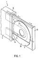
- each claw 24 As shown in Figure 2, formed in the low side of the external circumference of depression 21 are two roughly square-plate-shaped claws 24 that support part of the external circumference of optical disk 2. By inserting optical disk 2 between these claws 24 and depression 21, said optical disk 2 is mounted in disk tray 20. While the claws 24 in Figure 2 are shown as square-shaped, it will be understood that the claws 24 may be constructed as other shapes as long as they retain a disk mounted in the tray. In addition, square-shaped holes 25 are formed on both sides of each claw 24 along the external circumference of depression 21. Such holes are adapted to receive engagement parts 32 of a guide member 30 provided on the lower side of such a disk tray 20 as seen in Figures 1 and 2, which guides optical disk 2 between depression 21 and claws 24.
- guide member 30 has a cover 31, four engagement parts 32 provided on said cover 31, and a guide part 33, all preferably formed as an integral mold.
- Cover part 31, which is approximately large enough to cover part of optical disk 2 when attached to disk tray 20, traces a circular arc along the external circumference of depression 21 and is formed in a roughly semicircular shape.
- engagement parts 32 are preferably formed with a J-shaped cross-section and are provided in positions corresponding to holes 25 (see Figure 2).
- Guide member 33 has contact surface 33A, which comes into contact with the end faces of claws 24, and guide surface 33B, which is continuous with the disk support surfaces 24A of claws 24 that face optical disk 2 and slopes toward said disk support surface 24A, is formed with a triangular cross-sectional shape and is provided continuously along the circular arc of cover part 31.
- Engagement part 32 and guide part 33 are provided on the surface of cover part 31 that is opposite disk tray 20.
- guide member 30 is provided on disk tray 20 detachably. Protrusion distance H from the surface of disk tray 20 to the surface of cover part 31 when guide member 30 is attached to disk tray 20 is set so that guide member 30 does not touch device main body 10 when guide member 30 is attached to disk tray 20 and said disk tray 20 is inserted into device main body 10.
- optical disk 2 is mounted in such a disk device 1 .
- disk device 1 is to be used in the horizontal orientation, in which disk tray 20 is horizontal, one removes guide member 30. Then one inserts optical disk 2 between claws 24 and depression 21 and mounts said optical disk 2 into disk tray 20.
- disk device 1 is to be used in the vertical orientation, in which disk tray 20 is vertical, one attaches guide member 30.
- Figure 5A one inserts optical disk 20 by dropping it in between guide member 30 and disk tray 20.
- optical disk 2 slides along guide surface 33B and disk support surface 24A and is automatically guided between depression 21 and claws 24. Thereafter, optical disk 2 is mounted in disk tray 20.
- This procedure has several beneficial effects. For example, when mounting optical disk 2 in disk device 1 in the vertical orientation, by moving optical disk 2 along guide member 30, one can automatically guide said optical disk 2 between depression 21 and claws 24, which eliminates the inconvenience of mounting optical disk 2 that is caused by disk device 1 being in the vertical orientation, and facilitates the operation of mounting optical disk 2 into disk tray 20.
- guide member 30 is detachable, one can attach it if disk device 1 is to be used in the vertical orientation and remove it, or not use it at all, if it is to be used in the horizontal orientation. This makes the operation of mounting optical disk 2 easy, regardless of the orientation of disk device 1.
- inserting and mounting optical disk 2 into disk tray 20 can be done surely and easily, because guide part 33, which has guide surface 33B that is continuous with disk support surface 24A of claws 24, is provided on guide member 30, and optical disk 2 is guided between depression 21 and claws 24 by moving it toward depression 21 over guide surface 33B and sliding said optical disk 2 along guide surface 33B and disk support surface 24A. Furthermore, because cover part 31 of guide member 30 is formed large enough to cover part of optical disk 2, by dropping optical disk 2 in between guide member 30 and disk tray 20 from above disk tray 20, optical disk 2 can be simply guided between depression 21 and claws 24, thereby making the operation of mounting optical disk 2 in disk tray 20 easier. In addition, because engagement parts 32 are provided on guide member 30, when guide member 30 is to be attached to disk tray 20, it can be attached simply, just by causing engagement parts 32 to engage with holes 25 in disk tray 20, thereby facilitating the operation of attaching guide member 30.
- this invention is not limited to the aforesaid embodiment but includes other constructions.
- guide member 30 is made detachable with respect to disk tray 20 by forming holes 25 in disk tray 20 and providing engagement parts on guide member 30 that engage with holes 25, but the invention is not to be limited to this. That is, for example, there may be provided clamping parts on the guide member that clamp each claw of the disk tray from both sides so that the guide member itself is detachable from the claws of the disk tray. In this way, one obtains the same structure as disk device 1 of the aforesaid embodiment by providing a guide member on a general-purpose disk device.
- the guide member is attached to the disk tray by engaging engagement parts into holes, but this invention is not limited to this.
- the guide member may be attached to the disk tray by providing ball-shaped protrusions in the disk tray, providing fitting holes in the guide member into which these protrusions fit, and fitting the protrusions and the fitting holes together.
- the shape and composition of the attachment structure may be determined suitably in the implementation.
- the guide member need not have a cover part or guide part, as long as the optical disk can be guided between the depression and the claws; its shape and construction may be determined suitably in the implementation.
Landscapes
- Feeding And Guiding Record Carriers (AREA)
- Automatic Disk Changers (AREA)
Abstract
Description
Claims (14)
- A disk device comprising:a) a main body;b) a disk tray loadable into said main body and having a depression into which a disk, having an external circumference, is placed;c) said depression further comprising claw members that are adapted to support part of the external circumference of said disk, andd) a guide member removably attachable to said disk tray that guides said disk between said depression and said claw members.
- A disk device as described in claim 1, wherein said claw members further comprise a disk support surface and said guide member further comprises a guide surface that is continuous with said disk support surface.
- A disk device as described in claim 2, wherein said guide member is dimensioned to cover part of said disk.
- A disk device as described in claim 1, wherein said guide member comprises engagement parts that are engageable with engagement stop holes formed in said disk tray.
- A guide member for use with a disk device, said disk device having a disk tray with a depression formed therein and into which a disk is insertable and by which said disk is loaded into a device main body, said disk having an external circumference, said depression further comprising claw members having a disk support surface for supporting part of said external circumference of said disk, said guide member comprising:a) a guide surface continuous with said disk support surface for guiding an inserted disk between said depression and said claw members, andb) wherein said guide member is formed detachably with respect to said disk tray.
- A guide member as described in claim 5, wherein said guide member is dimensioned to cover part of a disk insertable into said disk tray.
- A disk tray for use with a disk device, said disk tray comprising:a) a depression having a peripheral edge into which a disk having an external circumference is placed;b) at least one claw member disposed along the peripheral edge of said depression and adapted to support part of the external circumference of said disk; andc) a guide member removably attachable to said disk tray that guides a disk between said depression and said claw members.
- A disk tray in accordance with claim 7, wherein said at least one claw member further comprises a disk support surface and said guide member further comprises a guide surface that is continuous with said disk support surface of said at least one claw member.
- A disk tray in accordance with claim 7, wherein said guide member is dimensioned to cover part of an inserted disk when said guide member is attached to said disk tray.
- A disk tray in accordance with claim 8, wherein said guide member further comprises engagement parts that are engageable with engagement stop holes formed in said disk tray.
- A disk tray in accordance with claim 8, wherein said at least one claw member has an end face and said guide surface has a contact surface that comes into contact with said end face of said at least one claw member during engagement of said guide member with said disk tray.
- A disk tray in accordance with claim 11, wherein said guide surface of said guide member forms an acute angle with respect to said contact surface of said guide member.
- A disk tray in accordance with claim 8, wherein said guide surface of said guide member has an arcuate shape.
- A disk tray in accordance with claim 10, wherein said engagement parts and said guide surface are formed integrally with said guide member.
Applications Claiming Priority (2)
| Application Number | Priority Date | Filing Date | Title |
|---|---|---|---|
| JP30098599A JP3406256B2 (en) | 1999-10-22 | 1999-10-22 | Disk device, disk tray, and guide member |
| JP30098599 | 1999-10-22 |
Publications (2)
| Publication Number | Publication Date |
|---|---|
| EP1094456A2 true EP1094456A2 (en) | 2001-04-25 |
| EP1094456A3 EP1094456A3 (en) | 2002-02-06 |
Family
ID=17891451
Family Applications (1)
| Application Number | Title | Priority Date | Filing Date |
|---|---|---|---|
| EP00122036A Withdrawn EP1094456A3 (en) | 1999-10-22 | 2000-10-11 | Disk device and guide member |
Country Status (3)
| Country | Link |
|---|---|
| US (1) | US6817021B1 (en) |
| EP (1) | EP1094456A3 (en) |
| JP (1) | JP3406256B2 (en) |
Cited By (2)
| Publication number | Priority date | Publication date | Assignee | Title |
|---|---|---|---|---|
| GB2378804A (en) * | 2001-08-15 | 2003-02-19 | Research Machines Plc | Disc support tray with disc covering portion |
| EP2792908A4 (en) * | 2011-12-09 | 2015-12-02 | Panasonic Corp | Rotating element assembly structure |
Families Citing this family (10)
| Publication number | Priority date | Publication date | Assignee | Title |
|---|---|---|---|---|
| US20030063898A1 (en) * | 2001-10-01 | 2003-04-03 | Sanyo Electric Co., Ltd | Disk player and television receiver incorporating same |
| CN1314035C (en) * | 2001-12-20 | 2007-05-02 | 松下电器产业株式会社 | Disc convey apparatus |
| EP1463050B1 (en) | 2001-12-25 | 2009-07-01 | Panasonic Corporation | Disc convey apparatus |
| KR100531784B1 (en) * | 2002-12-18 | 2005-11-29 | 엘지전자 주식회사 | Tray in optical disk player |
| JP2004234724A (en) * | 2003-01-29 | 2004-08-19 | Ricoh Co Ltd | Tray and disk rotating device |
| JP2006040425A (en) * | 2004-07-28 | 2006-02-09 | Orion Denki Kk | Optical disk unit |
| JP2006092583A (en) * | 2004-09-21 | 2006-04-06 | Matsushita Electric Ind Co Ltd | Disk unit |
| US7434236B2 (en) * | 2005-06-16 | 2008-10-07 | Quanta Storage Inc. | Tray-type optical disc drive with improved reliability under vertical disposition |
| JP4850287B2 (en) * | 2007-08-01 | 2012-01-11 | 富士通株式会社 | Storage device and electronic device |
| KR20140104619A (en) * | 2013-02-20 | 2014-08-29 | 도시바삼성스토리지테크놀러지코리아 주식회사 | Optical disk drive and main frame thereof |
Family Cites Families (16)
| Publication number | Priority date | Publication date | Assignee | Title |
|---|---|---|---|---|
| DE2210818A1 (en) * | 1972-03-07 | 1973-09-13 | Ted Bildplatten | METHOD AND EQUIPMENT FOR PLAYING BACK A DISC-SHAPED, IN PARTICULAR FOIL-SHAPED, RECORDING MEDIA AND A CARRIER PLATE FOR PERFORMING THE METHOD |
| JPH06251479A (en) * | 1993-02-25 | 1994-09-09 | Sony Corp | Disk device |
| JPH06325455A (en) * | 1993-05-14 | 1994-11-25 | Sony Corp | Disk device |
| JP3173224B2 (en) | 1993-05-19 | 2001-06-04 | 松下電器産業株式会社 | Disk unit |
| JPH0817118A (en) | 1994-04-25 | 1996-01-19 | Sony Corp | Disk unit |
| JP3552277B2 (en) * | 1994-05-31 | 2004-08-11 | ミツミ電機株式会社 | Disc playback device |
| JPH0845154A (en) * | 1994-08-02 | 1996-02-16 | Sanyo Electric Co Ltd | Tray for disk player |
| US5844874A (en) * | 1995-02-24 | 1998-12-01 | Kabushiki Kaisha Toshiba | Disc tray having a disc holding member |
| JPH08235715A (en) * | 1995-03-02 | 1996-09-13 | Ricoh Co Ltd | Drive device |
| JP3412321B2 (en) * | 1995-03-29 | 2003-06-03 | 日本電気株式会社 | Disk tray device |
| JP3551550B2 (en) * | 1995-05-26 | 2004-08-11 | ソニー株式会社 | Disk unit |
| JPH0955007A (en) * | 1995-08-15 | 1997-02-25 | Sony Corp | Disk unit |
| JP2882321B2 (en) * | 1995-09-20 | 1999-04-12 | 松下電器産業株式会社 | Recording and playback device |
| JPH11167760A (en) * | 1997-12-04 | 1999-06-22 | Sharp Corp | Disk unit |
| TW464041U (en) * | 1998-03-20 | 2001-11-11 | Benq Corp | Mechanism for limiting removeable disk for optical disk drive |
| US6301213B1 (en) * | 1999-10-04 | 2001-10-09 | Hewelett-Packard Company | Using a top-hinged shutter on a drive to supply a retaining force to hold a disc in position for vertical insertion |
-
1999
- 1999-10-22 JP JP30098599A patent/JP3406256B2/en not_active Expired - Lifetime
-
2000
- 2000-10-11 EP EP00122036A patent/EP1094456A3/en not_active Withdrawn
- 2000-10-18 US US09/691,403 patent/US6817021B1/en not_active Expired - Lifetime
Non-Patent Citations (1)
| Title |
|---|
| None * |
Cited By (3)
| Publication number | Priority date | Publication date | Assignee | Title |
|---|---|---|---|---|
| GB2378804A (en) * | 2001-08-15 | 2003-02-19 | Research Machines Plc | Disc support tray with disc covering portion |
| GB2378804B (en) * | 2001-08-15 | 2005-03-23 | Research Machines Plc | Optical disc drives |
| EP2792908A4 (en) * | 2011-12-09 | 2015-12-02 | Panasonic Corp | Rotating element assembly structure |
Also Published As
| Publication number | Publication date |
|---|---|
| JP3406256B2 (en) | 2003-05-12 |
| US6817021B1 (en) | 2004-11-09 |
| EP1094456A3 (en) | 2002-02-06 |
| JP2001126358A (en) | 2001-05-11 |
Similar Documents
| Publication | Publication Date | Title |
|---|---|---|
| US6817021B1 (en) | Disk device and guide member | |
| US4948022A (en) | Container for CD or cassette covers | |
| EP0791928B1 (en) | Case for encasing disc cartridge therein | |
| EP1079384B1 (en) | Disk device | |
| US6560184B2 (en) | Disk device having a detachable cover member | |
| US6262959B1 (en) | Disc cartridge | |
| CA1257388A (en) | Flexible magnetic diskette | |
| EP0331389A2 (en) | Assembly of a disc, a cartridge and an adapter and adapter therefore | |
| US4920441A (en) | Flexible magnetic diskette | |
| US5913419A (en) | Combination of a support for a disc-shaped recording medium and a holder for the support | |
| JP2549359B2 (en) | Optical pickup fixing device | |
| US6388838B1 (en) | Tape cartridge | |
| JP3412321B2 (en) | Disk tray device | |
| JP2508958B2 (en) | Disk adapter for disk cartridge | |
| US6811108B2 (en) | Recording tape cartridge | |
| JP2630287B2 (en) | Disc loading device | |
| JPH0110793Y2 (en) | ||
| JP3096668U (en) | Disk unit | |
| JPH0891134A (en) | Small object receiving rest for automobile | |
| JP2007234195A (en) | Disk driving device and disk attachment | |
| JPS58153279A (en) | Disk-storing case | |
| JP2000322867A (en) | Tape cartridge | |
| JPH10228744A (en) | Disk storage | |
| JP2000260152A (en) | Disk cartridge | |
| JPH10228746A (en) | Disk storage cartridge |
Legal Events
| Date | Code | Title | Description |
|---|---|---|---|
| PUAI | Public reference made under article 153(3) epc to a published international application that has entered the european phase |
Free format text: ORIGINAL CODE: 0009012 |
|
| AK | Designated contracting states |
Kind code of ref document: A2 Designated state(s): AT BE CH CY DE DK ES FI FR GB GR IE IT LI LU MC NL PT SE Kind code of ref document: A2 Designated state(s): DE ES FR GB IT |
|
| AX | Request for extension of the european patent |
Free format text: AL;LT;LV;MK;RO;SI |
|
| PUAL | Search report despatched |
Free format text: ORIGINAL CODE: 0009013 |
|
| AK | Designated contracting states |
Kind code of ref document: A3 Designated state(s): AT BE CH CY DE DK ES FI FR GB GR IE IT LI LU MC NL PT SE |
|
| AX | Request for extension of the european patent |
Free format text: AL;LT;LV;MK;RO;SI |
|
| RIC1 | Information provided on ipc code assigned before grant |
Free format text: 7G 11B 17/03 A, 7G 11B 17/04 B |
|
| 17P | Request for examination filed |
Effective date: 20020227 |
|
| AKX | Designation fees paid |
Free format text: DE ES FR GB IT |
|
| GRAP | Despatch of communication of intention to grant a patent |
Free format text: ORIGINAL CODE: EPIDOSNIGR1 |
|
| STAA | Information on the status of an ep patent application or granted ep patent |
Free format text: STATUS: THE APPLICATION IS DEEMED TO BE WITHDRAWN |
|
| 18D | Application deemed to be withdrawn |
Effective date: 20070719 |