EP1094229B1 - Rivet connection and method of connecting members by rivets - Google Patents
Rivet connection and method of connecting members by rivets Download PDFInfo
- Publication number
- EP1094229B1 EP1094229B1 EP00122698A EP00122698A EP1094229B1 EP 1094229 B1 EP1094229 B1 EP 1094229B1 EP 00122698 A EP00122698 A EP 00122698A EP 00122698 A EP00122698 A EP 00122698A EP 1094229 B1 EP1094229 B1 EP 1094229B1
- Authority
- EP
- European Patent Office
- Prior art keywords
- hollow pin
- end portion
- pin
- hollow
- metal
- Prior art date
- Legal status (The legal status is an assumption and is not a legal conclusion. Google has not performed a legal analysis and makes no representation as to the accuracy of the status listed.)
- Expired - Lifetime
Links
- 238000000034 method Methods 0.000 title claims description 15
- 229910000838 Al alloy Inorganic materials 0.000 claims description 14
- 239000000463 material Substances 0.000 claims description 13
- 229910052751 metal Inorganic materials 0.000 claims description 12
- 239000002184 metal Substances 0.000 claims description 12
- 230000007797 corrosion Effects 0.000 claims description 10
- 238000005260 corrosion Methods 0.000 claims description 10
- CWYNVVGOOAEACU-UHFFFAOYSA-N Fe2+ Chemical compound [Fe+2] CWYNVVGOOAEACU-UHFFFAOYSA-N 0.000 claims description 8
- PXHVJJICTQNCMI-UHFFFAOYSA-N Nickel Chemical compound [Ni] PXHVJJICTQNCMI-UHFFFAOYSA-N 0.000 claims description 8
- 238000007747 plating Methods 0.000 claims description 8
- 239000011651 chromium Substances 0.000 claims description 5
- VYZAMTAEIAYCRO-UHFFFAOYSA-N Chromium Chemical compound [Cr] VYZAMTAEIAYCRO-UHFFFAOYSA-N 0.000 claims description 4
- 229910052804 chromium Inorganic materials 0.000 claims description 4
- 229910052759 nickel Inorganic materials 0.000 claims description 4
- 238000005096 rolling process Methods 0.000 claims description 4
- 239000011248 coating agent Substances 0.000 description 7
- 238000000576 coating method Methods 0.000 description 7
- 241000282472 Canis lupus familiaris Species 0.000 description 4
- 238000010276 construction Methods 0.000 description 2
- 230000001419 dependent effect Effects 0.000 description 2
- 238000004519 manufacturing process Methods 0.000 description 2
- 229910000831 Steel Inorganic materials 0.000 description 1
- 230000004323 axial length Effects 0.000 description 1
- ZCDOYSPFYFSLEW-UHFFFAOYSA-N chromate(2-) Chemical compound [O-][Cr]([O-])(=O)=O ZCDOYSPFYFSLEW-UHFFFAOYSA-N 0.000 description 1
- 229910052802 copper Inorganic materials 0.000 description 1
- 238000005336 cracking Methods 0.000 description 1
- 208000018999 crinkle Diseases 0.000 description 1
- 239000004615 ingredient Substances 0.000 description 1
- 239000007769 metal material Substances 0.000 description 1
- 230000003647 oxidation Effects 0.000 description 1
- 238000007254 oxidation reaction Methods 0.000 description 1
- 239000010935 stainless steel Substances 0.000 description 1
- 229910001220 stainless steel Inorganic materials 0.000 description 1
- 239000010959 steel Substances 0.000 description 1
- 238000004381 surface treatment Methods 0.000 description 1
Images


Classifications
-
- B—PERFORMING OPERATIONS; TRANSPORTING
- B21—MECHANICAL METAL-WORKING WITHOUT ESSENTIALLY REMOVING MATERIAL; PUNCHING METAL
- B21J—FORGING; HAMMERING; PRESSING METAL; RIVETING; FORGE FURNACES
- B21J15/00—Riveting
- B21J15/10—Riveting machines
- B21J15/12—Riveting machines with tools or tool parts having a movement additional to the feed movement, e.g. spin
-
- B—PERFORMING OPERATIONS; TRANSPORTING
- B21—MECHANICAL METAL-WORKING WITHOUT ESSENTIALLY REMOVING MATERIAL; PUNCHING METAL
- B21J—FORGING; HAMMERING; PRESSING METAL; RIVETING; FORGE FURNACES
- B21J15/00—Riveting
- B21J15/02—Riveting procedures
- B21J15/04—Riveting hollow rivets mechanically
- B21J15/046—Riveting hollow rivets mechanically by edge-curling
-
- F—MECHANICAL ENGINEERING; LIGHTING; HEATING; WEAPONS; BLASTING
- F16—ENGINEERING ELEMENTS AND UNITS; GENERAL MEASURES FOR PRODUCING AND MAINTAINING EFFECTIVE FUNCTIONING OF MACHINES OR INSTALLATIONS; THERMAL INSULATION IN GENERAL
- F16B—DEVICES FOR FASTENING OR SECURING CONSTRUCTIONAL ELEMENTS OR MACHINE PARTS TOGETHER, e.g. NAILS, BOLTS, CIRCLIPS, CLAMPS, CLIPS OR WEDGES; JOINTS OR JOINTING
- F16B19/00—Bolts without screw-thread; Pins, including deformable elements; Rivets
- F16B19/04—Rivets; Spigots or the like fastened by riveting
- F16B19/08—Hollow rivets; Multi-part rivets
- F16B19/10—Hollow rivets; Multi-part rivets fastened by expanding mechanically
-
- F—MECHANICAL ENGINEERING; LIGHTING; HEATING; WEAPONS; BLASTING
- F16—ENGINEERING ELEMENTS AND UNITS; GENERAL MEASURES FOR PRODUCING AND MAINTAINING EFFECTIVE FUNCTIONING OF MACHINES OR INSTALLATIONS; THERMAL INSULATION IN GENERAL
- F16B—DEVICES FOR FASTENING OR SECURING CONSTRUCTIONAL ELEMENTS OR MACHINE PARTS TOGETHER, e.g. NAILS, BOLTS, CIRCLIPS, CLAMPS, CLIPS OR WEDGES; JOINTS OR JOINTING
- F16B5/00—Joining sheets or plates, e.g. panels, to one another or to strips or bars parallel to them
- F16B5/04—Joining sheets or plates, e.g. panels, to one another or to strips or bars parallel to them by means of riveting
-
- F—MECHANICAL ENGINEERING; LIGHTING; HEATING; WEAPONS; BLASTING
- F16—ENGINEERING ELEMENTS AND UNITS; GENERAL MEASURES FOR PRODUCING AND MAINTAINING EFFECTIVE FUNCTIONING OF MACHINES OR INSTALLATIONS; THERMAL INSULATION IN GENERAL
- F16D—COUPLINGS FOR TRANSMITTING ROTATION; CLUTCHES; BRAKES
- F16D65/00—Parts or details
- F16D65/02—Braking members; Mounting thereof
- F16D65/12—Discs; Drums for disc brakes
-
- F—MECHANICAL ENGINEERING; LIGHTING; HEATING; WEAPONS; BLASTING
- F16—ENGINEERING ELEMENTS AND UNITS; GENERAL MEASURES FOR PRODUCING AND MAINTAINING EFFECTIVE FUNCTIONING OF MACHINES OR INSTALLATIONS; THERMAL INSULATION IN GENERAL
- F16D—COUPLINGS FOR TRANSMITTING ROTATION; CLUTCHES; BRAKES
- F16D65/00—Parts or details
- F16D65/02—Braking members; Mounting thereof
- F16D2065/13—Parts or details of discs or drums
- F16D2065/134—Connection
- F16D2065/1348—Connection resilient
-
- F—MECHANICAL ENGINEERING; LIGHTING; HEATING; WEAPONS; BLASTING
- F16—ENGINEERING ELEMENTS AND UNITS; GENERAL MEASURES FOR PRODUCING AND MAINTAINING EFFECTIVE FUNCTIONING OF MACHINES OR INSTALLATIONS; THERMAL INSULATION IN GENERAL
- F16D—COUPLINGS FOR TRANSMITTING ROTATION; CLUTCHES; BRAKES
- F16D65/00—Parts or details
- F16D65/02—Braking members; Mounting thereof
- F16D2065/13—Parts or details of discs or drums
- F16D2065/134—Connection
- F16D2065/1356—Connection interlocking
- F16D2065/1368—Connection interlocking with relative movement both radially and axially
-
- F—MECHANICAL ENGINEERING; LIGHTING; HEATING; WEAPONS; BLASTING
- F16—ENGINEERING ELEMENTS AND UNITS; GENERAL MEASURES FOR PRODUCING AND MAINTAINING EFFECTIVE FUNCTIONING OF MACHINES OR INSTALLATIONS; THERMAL INSULATION IN GENERAL
- F16D—COUPLINGS FOR TRANSMITTING ROTATION; CLUTCHES; BRAKES
- F16D65/00—Parts or details
- F16D65/02—Braking members; Mounting thereof
- F16D2065/13—Parts or details of discs or drums
- F16D2065/134—Connection
- F16D2065/1376—Connection inner circumference
-
- F—MECHANICAL ENGINEERING; LIGHTING; HEATING; WEAPONS; BLASTING
- F16—ENGINEERING ELEMENTS AND UNITS; GENERAL MEASURES FOR PRODUCING AND MAINTAINING EFFECTIVE FUNCTIONING OF MACHINES OR INSTALLATIONS; THERMAL INSULATION IN GENERAL
- F16D—COUPLINGS FOR TRANSMITTING ROTATION; CLUTCHES; BRAKES
- F16D65/00—Parts or details
- F16D65/02—Braking members; Mounting thereof
- F16D2065/13—Parts or details of discs or drums
- F16D2065/134—Connection
- F16D2065/1392—Connection elements
-
- F—MECHANICAL ENGINEERING; LIGHTING; HEATING; WEAPONS; BLASTING
- F16—ENGINEERING ELEMENTS AND UNITS; GENERAL MEASURES FOR PRODUCING AND MAINTAINING EFFECTIVE FUNCTIONING OF MACHINES OR INSTALLATIONS; THERMAL INSULATION IN GENERAL
- F16D—COUPLINGS FOR TRANSMITTING ROTATION; CLUTCHES; BRAKES
- F16D65/00—Parts or details
- F16D65/02—Braking members; Mounting thereof
- F16D2065/13—Parts or details of discs or drums
- F16D2065/134—Connection
- F16D2065/1392—Connection elements
- F16D2065/1396—Ancillary resilient elements, e.g. anti-rattle or retraction springs
-
- Y—GENERAL TAGGING OF NEW TECHNOLOGICAL DEVELOPMENTS; GENERAL TAGGING OF CROSS-SECTIONAL TECHNOLOGIES SPANNING OVER SEVERAL SECTIONS OF THE IPC; TECHNICAL SUBJECTS COVERED BY FORMER USPC CROSS-REFERENCE ART COLLECTIONS [XRACs] AND DIGESTS
- Y10—TECHNICAL SUBJECTS COVERED BY FORMER USPC
- Y10T—TECHNICAL SUBJECTS COVERED BY FORMER US CLASSIFICATION
- Y10T29/00—Metal working
- Y10T29/49—Method of mechanical manufacture
- Y10T29/49826—Assembling or joining
-
- Y—GENERAL TAGGING OF NEW TECHNOLOGICAL DEVELOPMENTS; GENERAL TAGGING OF CROSS-SECTIONAL TECHNOLOGIES SPANNING OVER SEVERAL SECTIONS OF THE IPC; TECHNICAL SUBJECTS COVERED BY FORMER USPC CROSS-REFERENCE ART COLLECTIONS [XRACs] AND DIGESTS
- Y10—TECHNICAL SUBJECTS COVERED BY FORMER USPC
- Y10T—TECHNICAL SUBJECTS COVERED BY FORMER US CLASSIFICATION
- Y10T29/00—Metal working
- Y10T29/49—Method of mechanical manufacture
- Y10T29/49826—Assembling or joining
- Y10T29/49908—Joining by deforming
-
- Y—GENERAL TAGGING OF NEW TECHNOLOGICAL DEVELOPMENTS; GENERAL TAGGING OF CROSS-SECTIONAL TECHNOLOGIES SPANNING OVER SEVERAL SECTIONS OF THE IPC; TECHNICAL SUBJECTS COVERED BY FORMER USPC CROSS-REFERENCE ART COLLECTIONS [XRACs] AND DIGESTS
- Y10—TECHNICAL SUBJECTS COVERED BY FORMER USPC
- Y10T—TECHNICAL SUBJECTS COVERED BY FORMER US CLASSIFICATION
- Y10T29/00—Metal working
- Y10T29/49—Method of mechanical manufacture
- Y10T29/49826—Assembling or joining
- Y10T29/49908—Joining by deforming
- Y10T29/49915—Overedge assembling of seated part
-
- Y—GENERAL TAGGING OF NEW TECHNOLOGICAL DEVELOPMENTS; GENERAL TAGGING OF CROSS-SECTIONAL TECHNOLOGIES SPANNING OVER SEVERAL SECTIONS OF THE IPC; TECHNICAL SUBJECTS COVERED BY FORMER USPC CROSS-REFERENCE ART COLLECTIONS [XRACs] AND DIGESTS
- Y10—TECHNICAL SUBJECTS COVERED BY FORMER USPC
- Y10T—TECHNICAL SUBJECTS COVERED BY FORMER US CLASSIFICATION
- Y10T29/00—Metal working
- Y10T29/49—Method of mechanical manufacture
- Y10T29/49826—Assembling or joining
- Y10T29/49908—Joining by deforming
- Y10T29/49936—Surface interlocking
-
- Y—GENERAL TAGGING OF NEW TECHNOLOGICAL DEVELOPMENTS; GENERAL TAGGING OF CROSS-SECTIONAL TECHNOLOGIES SPANNING OVER SEVERAL SECTIONS OF THE IPC; TECHNICAL SUBJECTS COVERED BY FORMER USPC CROSS-REFERENCE ART COLLECTIONS [XRACs] AND DIGESTS
- Y10—TECHNICAL SUBJECTS COVERED BY FORMER USPC
- Y10T—TECHNICAL SUBJECTS COVERED BY FORMER US CLASSIFICATION
- Y10T29/00—Metal working
- Y10T29/49—Method of mechanical manufacture
- Y10T29/49826—Assembling or joining
- Y10T29/49947—Assembling or joining by applying separate fastener
-
- Y—GENERAL TAGGING OF NEW TECHNOLOGICAL DEVELOPMENTS; GENERAL TAGGING OF CROSS-SECTIONAL TECHNOLOGIES SPANNING OVER SEVERAL SECTIONS OF THE IPC; TECHNICAL SUBJECTS COVERED BY FORMER USPC CROSS-REFERENCE ART COLLECTIONS [XRACs] AND DIGESTS
- Y10—TECHNICAL SUBJECTS COVERED BY FORMER USPC
- Y10T—TECHNICAL SUBJECTS COVERED BY FORMER US CLASSIFICATION
- Y10T29/00—Metal working
- Y10T29/49—Method of mechanical manufacture
- Y10T29/49826—Assembling or joining
- Y10T29/49947—Assembling or joining by applying separate fastener
- Y10T29/49954—Fastener deformed after application
-
- Y—GENERAL TAGGING OF NEW TECHNOLOGICAL DEVELOPMENTS; GENERAL TAGGING OF CROSS-SECTIONAL TECHNOLOGIES SPANNING OVER SEVERAL SECTIONS OF THE IPC; TECHNICAL SUBJECTS COVERED BY FORMER USPC CROSS-REFERENCE ART COLLECTIONS [XRACs] AND DIGESTS
- Y10—TECHNICAL SUBJECTS COVERED BY FORMER USPC
- Y10T—TECHNICAL SUBJECTS COVERED BY FORMER US CLASSIFICATION
- Y10T403/00—Joints and connections
- Y10T403/49—Member deformed in situ
- Y10T403/4933—Member deformed in situ by separate, deformable element
Definitions
- the present invention relates, in general, to a pin connection structure and to a method of connecting members by a pin. Specifically, it also relates to a pin connection structure for use in a floating type brake disc assembly and to a method of connecting the floating type brake disc assembly by pins, the brake disc assembly being for use in a motorcycle.
- a brake disc which comprises an inner mounting member and outer annular braking member and a driving connection between the two members.
- the braking member has the usual flat annular braking surfaces.
- the driving connection comprises a square shaped drive dog which engages in corresponding notches in the outer periphery of the mounting member and the inner periphery of the braking member. Axial location is by stop flanges secured together through an aperture in the drive dog. The axial length of the dog is greater than the thickness of the disc members so the flanges, in engagement with the axial end faces, allow some axial movement. A crinkle washer controls the relative axial positions.
- the applicants of the present invention have been studying how to improve the corrosion resistivity of hollow pins made of various metallic materials such as aluminum alloys, ferrous materials, or the like, by providing them with surface treatment.
- an aluminum alloy is used as a material for the hollow pins which are used in a floating type brake disc assembly
- the heat generated in the disc due to the friction can be easily transferred to the hub side and, consequently, the heat easily dissipates also from the pins themselves.
- the disc can be prevented from being distorted by the friction heat, and also the pins can be made smaller in weight.
- an aluminum alloy having applied to the surface thereof a corrosion resistant surface-treated layer such as an oxide coating film (anodic oxidation coating), a chromate film, a metallic coating, a dying coating, a colored coating, or the like, is used under the below-described condition, for making a hollow pin as described below, the surface-treated layer on an end portion of the hollow pin is damaged at the time of caulking, whereby the base surface of the end portion of the pin is exposed to the outside, resulting in a poor corrosion resistivity and a poor aesthetic appearance.
- an oxide coating film anodic oxidation coating
- chromate film chromate film
- metallic coating a metallic coating
- a dying coating a colored coating, or the like
- the above-described condition in question is that the shape of a center hole of the hollow pin is formed into the same shape as that of a pin which is designed on condition that it is made in a stainless steel or in a coiled steel material.
- a pin with such a shape is disclosed, for example, in Published Unexamined Japanese Patent Application No. 312700/1996.
- the shape in question is one in which the center hole in the hollow pin is made cylindrical up to the end portion on that side of the pin which is to be caulked, or one in which the end portion of the center hole is chamfered into a linearly tapered shape (i.e., into a shape tapered or beveled in a straight line).
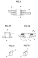
- FIGS. 7A and 7B show a construction of a conventional hollow pin as applied to floating type brake disc assembly for use in a motorcycle.
- the hollow pin is made of an aluminum alloy and which has applied thereto an oxide coating film and in which an end portion of the center hole is provided with a small taper (i.e., a bevel in a straight line).
- the hollow pin shown in FIG. 7A has a taper a2 in an inner circumferential end portion of the center hole al. This hollow pin "a” is inserted into a connecting hole made of semicircular dents b1, c1 formed in a hub b and a disc c, respectively.
- a washer d1, a coned spring disc e, and a fixing washer d2 are fitted onto an outside of the hollow pin "a” and an end portion of the hollow pin "a” is caulked to thereby radially expand the end portion.
- the fixing washer d2 is thus fixed in position by caulking.
- the shape of the end portion changes from the one shown in FIG. 7C to the one shown in FIG. 7D.
- a ring-shaped crack f occurs to the oxide film on the end surface, whereby the base surface of the aluminum alloy will be exposed to the outside, resulting in a poor corrosion resistivity and in a poor aesthetic appearance. If the end surface is not tapered, the cracking of the oxide film becomes still larger.
- the present invention has an object of providing a pin connection structure, in general, and a method of connecting, in general, at least two members by a pin.
- the present invention is a floating type disc brake assembly according to claim 1.
- Preferred embodiments are defined in dependent claims.
- FIG. 1 is a front view of a floating type brake disc assembly with part thereof being omitted.
- the brake disc assembly is intended to be an example in which the pin connection structure of the present invention is applied.
- Reference numeral 1 denotes a floating type brake disc assembly
- reference numeral 2 denotes a hub which is coupled to a shaft of a vehicle, i.e., a motorcycle in this embodiment
- reference numeral 3 denotes an annular disc for applying thereto a braking force.
- the hub 2 and the disc 3 are disposed concentrically to each other with a small clearance 4 therebetween.
- a pair of semicircular connecting dents or recesses 5, 6 are provided in the hub 2 and the disc 3, respectively, in predetermined sets at a predetermined circumferential distance from each set. Circular discontinuous inserting holes 7 for inserting hollow pins 8 therethrough are thus formed by the respective pair of connecting dents 5, 6.
- Each of the hollow pins 8 to be inserted into each of the inserting holes 7 is made up, as shown in FIG. 2A, of a flange 8a on one axial end the hollow pin 8, and a center hole 8b which extends along an axial line of the hollow pin 8.
- a rounded or curved portion 8d which has a convex shape in at least part of the corner portion as explained in more detail hereinbelow with reference to FIGS. 4A through 4D.
- the hollow pin 8 As a material for the hollow pin 8, the following may be used, i.e., an aluminum alloy under JIS (Japanese Industrial Standards) No. 6061T6, which specifies a chief ingredient, in mass %, of Mg: 0.8 - 1.2%, Si: 0.40 - 0.8%, Cu: 0.15 - 0.40%; Cr: 0.04 - 0.35%; the rest being Al.
- JIS Japanese Industrial Standards
- the hollow pin 8 has applied to the surface thereof an oxide corrosion-resistant film or coating.
- the hollow pin 8 is inserted into the inserting hole 7.
- a washer 9, a washer 10 and a fixing washer 11 are then inserted onto an outer surface of the hollow pin 8 in the order mentioned.
- That end of the hollow pin 8 which is on the opposite side of the flange 8a, more particularly, the range from the portion formed into a convex 8d to the end surface 8c, is caulked by means of a caulking means to be described hereinafter.
- a radially enlarged portion 8e as shown in FIG. 2D is formed to thereby fix the fixing washer 11 in position.
- the hollow pin 8 is formed into a convex shape in at least part of the end portion to be caulked such that the end portion is free from a sharply bent edge on which the caulking pressure is concentrated. Therefore, the caulking pressure is dispersed or distributed on the caulked surface to thereby prevent the damages to the surface-treated layer.
- a hollow pin is used, the hollow pin being made of an aluminum alloy with a corrosion-resistant layer thereon.
- the material for the hollow pin is not limited to an aluminum alloy but may alternatively be a soft ferrous metal which is capable of being caulked.
- As a surface-treated layer for the ferrous metal chromium plating, nickel plating, or the like may be used.
- FIGS. 3A and 3B show a modified example using a hollow pin 8 with a stepped portion 12.
- the hollow pin 8 is made up of a small-diameter portion and a large-diameter portion which lies on the side of a flange 8a.
- the stepped portion 12 is formed in a portion where the small-diameter portion changes to the large-diameter portion.
- the large-diameter portion of the hollow pin 8 is inserted into the inserting hole 7.
- a coned spring washer 10 is inserted into the small-diameter portion so as to be seated on the stepped portion.
- a fixing washer 11 is placed on top of the coned spring washer 10, and the end of the hollow pin 8 is then caulked onto the fixing washer 11 in the same way as in the above-described example.
- the fixing washer 11 can thus be fixed in position without damaging the surface-treated layer.
- FIGS. 4A through 4G show various examples of the shape of that end portion of the hollow pin 8 which is caulked.
- that one end of the hollow pin 8 which is subsequently caulked radially outward (also called a caulked end) is the same as that shown in FIG. 2.
- the front end portion 8d which is in the concave shape is formed at the corner of a front inner periphery of the center hole 8b.
- FIG. 4B is the same as that shown in FIG. 3A.
- a semicircular curved portion 8d1 is formed both in the inner periphery and in the outer periphery of the caulked end.
- a front end portion in an elliptic shape is formed on the inner periphery of the center hole 8b to such a degree that the flat end surface 8c2 remains partially in the radially outer portion.
- curved portion 8d3 in a parabolic shape is formed both in the inner periphery and in the outer periphery of the caulked end.
- the hollow pin 8 is formed such that the caulked end has a curved portion 8d, 8d1, 8d2, 8d3 which is formed into a convex shape in the portion to which a pressurizing force is applied at the time of caulking.
- the curved portion is made up of one tapered or beveled surface (i.e., having a straight line) combined with one or two convex surfaces.
- the front end portion 8d4 is made up of a tapered portion 8d41 and convex surfaces 8d42, 8d43 which are formed on both axial sides of the tapered portion 8d41.
- the front end portion 8d5 is made up of a tapered portion 8d41 and a convex surface 8d42 which is formed only on an axially outer side of the tapered portion 8d41.
- FIG. 4E the front end portion 8d4 is made up of a tapered portion 8d41 and convex surfaces 8d42, 8d43 which are formed on both axial sides of the tapered portion 8d41.
- the front end portion 8d5 is made up of a tapered portion 8d41 and a convex surface 8d42 which is formed only on an axially outer side of the tapered portion 8d41.
- the front end portion 8d6 is made up of a tapered portion 8d41 and a convex surface 8d43 which is formed only on an axially inner side of the tapered portion 8d41.
- the hollow pin 8 is formed into a convex shape in at least part of the end portion to be caulked such that the caulked end is free from a sharply bent edge on which the caulking pressure is concentrated. It is thus so arranged that the caulking pressure is dispersed or distributed on the caulked surface to thereby prevent the damages to the surface-treated layer.
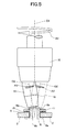
- FIG. 5 shows an outline of a caulking apparatus which is used to caulk the hollow pin 8 of the present invention.
- the caulking apparatus is made up of a head 15 which is rotatable about a vertical axial line O1, and an insert 16 which is rotatable about an inclined central axial line 02 and which is rotatably supported on the head 15.
- a pressurizing surface 16a which is formed at an obtuse angle.
- the above-described embodiments have a construction in which the flange 8a is disposed on a side opposite to the caulked end.
- the present invention can also be applied to an example in which a washer is fixed instead of the flange 8a.
- FIG. 6 shows a pin connection structure in which at least two members in general are connected together by a pin.
- a plate members 20 and 21 are fixed together by means of a hollow pin 8.
- the hollow pin 8 has the same structure as in the above-described example and, therefore, detailed explanation about the hollow pin 8 itself is not repeated here.
- the hollow pin 8 is caulked radially outward to thereby fix the two members together, the surface-treated layer on the end surface 8c has not been damaged.
- the hollow pin since the hollow pin has a convex shape in at least part of the end portion to be caulked, the caulking pressure will not be concentrated. Accordingly, the surface-treated layer on the caulked end of the hollow pin will not be damaged. Therefore, a hollow pin which is superior in corrosion resistivity and in aesthetic appearance can be obtained.
- the hollow pin becomes superior in heat transfer, and thus can prevent the thermal distortion of the connected material, i.e. a brake disc assembly in the specific example.
- the caulked surface is formed into a concave shape in at least part of the end portion, there will occur no concentration of the caulking pressure.
- the caulking is gradually performed by means of rolling with a roller, there will occur no damage to the surface-treated layer on the end surface of the hollow pin. Therefore, at least two members, as exemplified by a brake disc assembly, with the structure of pin connection can be easily obtained.
- the hollow pin by using an aluminum alloy or a ferrous material for manufacturing the hollow pin, the hollow pin can be easily caulked with a smaller resistance.
Landscapes
- Engineering & Computer Science (AREA)
- General Engineering & Computer Science (AREA)
- Mechanical Engineering (AREA)
- Braking Arrangements (AREA)
Description
- The present invention relates, in general, to a pin connection structure and to a method of connecting members by a pin. Specifically, it also relates to a pin connection structure for use in a floating type brake disc assembly and to a method of connecting the floating type brake disc assembly by pins, the brake disc assembly being for use in a motorcycle.
- Document US4645041 being the closest prior art discloses a brake disc which comprises an inner mounting member and outer annular braking member and a driving connection between the two members. The braking member has the usual flat annular braking surfaces. The driving connection comprises a square shaped drive dog which engages in corresponding notches in the outer periphery of the mounting member and the inner periphery of the braking member. Axial location is by stop flanges secured together through an aperture in the drive dog. The axial length of the dog is greater than the thickness of the disc members so the flanges, in engagement with the axial end faces, allow some axial movement. A crinkle washer controls the relative axial positions. There are a plurality of drive dogs spaced equally around the disc.
- As an art of connecting at least two members by a pin, there has been generally practiced to employ a pin connection structure with a hollow pin in order to reduce the weight of the pin. Further, there has also been generally practiced to provide the pin with a surface-treated layer in order to improve the durability of the pin. Specifically, the above-described pin connection structure is also employed in connecting a floating type brake disc assembly by pins.
- The applicants of the present invention have been studying how to improve the corrosion resistivity of hollow pins made of various metallic materials such as aluminum alloys, ferrous materials, or the like, by providing them with surface treatment. When an aluminum alloy is used as a material for the hollow pins which are used in a floating type brake disc assembly, the heat generated in the disc due to the friction can be easily transferred to the hub side and, consequently, the heat easily dissipates also from the pins themselves. As a result, the disc can be prevented from being distorted by the friction heat, and also the pins can be made smaller in weight.
- However, if an aluminum alloy having applied to the surface thereof a corrosion resistant surface-treated layer such as an oxide coating film (anodic oxidation coating), a chromate film, a metallic coating, a dying coating, a colored coating, or the like, is used under the below-described condition, for making a hollow pin as described below, the surface-treated layer on an end portion of the hollow pin is damaged at the time of caulking, whereby the base surface of the end portion of the pin is exposed to the outside, resulting in a poor corrosion resistivity and a poor aesthetic appearance. The above-described condition in question is that the shape of a center hole of the hollow pin is formed into the same shape as that of a pin which is designed on condition that it is made in a stainless steel or in a coiled steel material. Such a pin with such a shape is disclosed, for example, in Published Unexamined Japanese Patent Application No. 312700/1996. In more detail, the shape in question is one in which the center hole in the hollow pin is made cylindrical up to the end portion on that side of the pin which is to be caulked, or one in which the end portion of the center hole is chamfered into a linearly tapered shape (i.e., into a shape tapered or beveled in a straight line).
- FIGS. 7A and 7B show a construction of a conventional hollow pin as applied to floating type brake disc assembly for use in a motorcycle. The hollow pin is made of an aluminum alloy and which has applied thereto an oxide coating film and in which an end portion of the center hole is provided with a small taper (i.e., a bevel in a straight line). The hollow pin shown in FIG. 7A has a taper a2 in an inner circumferential end portion of the center hole al. This hollow pin "a" is inserted into a connecting hole made of semicircular dents b1, c1 formed in a hub b and a disc c, respectively. A washer d1, a coned spring disc e, and a fixing washer d2 are fitted onto an outside of the hollow pin "a" and an end portion of the hollow pin "a" is caulked to thereby radially expand the end portion. The fixing washer d2 is thus fixed in position by caulking. When the end portion is caulked, however, the shape of the end portion changes from the one shown in FIG. 7C to the one shown in FIG. 7D. At this time, it has been found that a ring-shaped crack f occurs to the oxide film on the end surface, whereby the base surface of the aluminum alloy will be exposed to the outside, resulting in a poor corrosion resistivity and in a poor aesthetic appearance. If the end surface is not tapered, the cracking of the oxide film becomes still larger.
- In view of the above points, the present invention has an object of providing a pin connection structure, in general, and a method of connecting, in general, at least two members by a pin.
- In order to attain the above and other objects, the present invention is a floating type disc brake assembly according to claim 1. Preferred embodiments are defined in dependent claims.
- In another aspect of the present invention, there is provided a method of connecting two members by a pin according to
claims - Preferred embodiments are defined in dependent claims.
- The above and other objects and the attendant advantages of the present invention will become readily apparent by reference to the following detailed description when considered in conjunction with the accompanying drawings wherein:
- FIG. 1 is a partial front view of a pin connection structure as applied to a floating type brake disc assembly according to the present invention;
- FIGS. 2A and 2B are sectional views of a hollow pin and a brake disc assembly, respectively, and FIGS. 2C and 2D are partial perspective views of that portion of the hollow pin which is before and after caulking, respectively, according to the present invention;
- FIGS. 3A and 3B are sectional views of a modified example of the present invention;
- FIGS. 4A through 4G are cross sectional views of that end portion of the hollow pin which is caulked;
- FIG. 5 is a side view of a caulking apparatus to be used in caulking the end portion of the hollow pin;
- FIG. 6 is a sectional view of a pin connection structure, in general, for connecting at least two members together according to the present invention; and
- FIGS. 7A - 7D show conventional examples, in which FIG. 7A is a sectional view of a conventional pin, FIG. 7B is a sectional view of a conventional pin connection structure as applied to a brake disc assembly, FIG. 7C is a partial perspective view of an end portion of a conventional hollow pin with a taper (i.e., in a straight line), and FIG. 7D is a conventional hollow pin with a crack in a surface-treated layer after caulking.
- Preferred embodiments of the present invention will now be described with reference to the enclosed drawings. FIG. 1 is a front view of a floating type brake disc assembly with part thereof being omitted. The brake disc assembly is intended to be an example in which the pin connection structure of the present invention is applied.
- Reference numeral 1 denotes a floating type brake disc assembly,
reference numeral 2 denotes a hub which is coupled to a shaft of a vehicle, i.e., a motorcycle in this embodiment,reference numeral 3 denotes an annular disc for applying thereto a braking force. Thehub 2 and thedisc 3 are disposed concentrically to each other with a small clearance 4 therebetween. A pair of semicircular connecting dents orrecesses 5, 6 are provided in thehub 2 and thedisc 3, respectively, in predetermined sets at a predetermined circumferential distance from each set. Circular discontinuous insertingholes 7 for insertinghollow pins 8 therethrough are thus formed by the respective pair of connectingdents 5, 6. Each of thehollow pins 8 to be inserted into each of the insertingholes 7 is made up, as shown in FIG. 2A, of aflange 8a on one axial end thehollow pin 8, and acenter hole 8b which extends along an axial line of thehollow pin 8. In the corner portion between the inner circumference of thecenter hole 8b and thatend surface 8c of thehollow pin 8 which is at a right angle to the axial line, there is formed a rounded orcurved portion 8d which has a convex shape in at least part of the corner portion as explained in more detail hereinbelow with reference to FIGS. 4A through 4D. As a material for thehollow pin 8, the following may be used, i.e., an aluminum alloy under JIS (Japanese Industrial Standards) No. 6061T6, which specifies a chief ingredient, in mass %, of Mg: 0.8 - 1.2%, Si: 0.40 - 0.8%, Cu: 0.15 - 0.40%; Cr: 0.04 - 0.35%; the rest being Al. Thehollow pin 8 has applied to the surface thereof an oxide corrosion-resistant film or coating. - As shown in FIG. 2B, the
hollow pin 8 is inserted into the insertinghole 7. Awasher 9, awasher 10 and a fixingwasher 11 are then inserted onto an outer surface of thehollow pin 8 in the order mentioned. That end of thehollow pin 8 which is on the opposite side of theflange 8a, more particularly, the range from the portion formed into a convex 8d to theend surface 8c, is caulked by means of a caulking means to be described hereinafter. As a result of the caulking, a radiallyenlarged portion 8e as shown in FIG. 2D is formed to thereby fix the fixingwasher 11 in position. By caulking the end of thehollow pin 8 in this manner, the surface-treated layer is not damaged. This is because thehollow pin 8 is formed into a convex shape in at least part of the end portion to be caulked such that the end portion is free from a sharply bent edge on which the caulking pressure is concentrated. Therefore, the caulking pressure is dispersed or distributed on the caulked surface to thereby prevent the damages to the surface-treated layer. - An explanation has so far been made about an example in which a hollow pin is used, the hollow pin being made of an aluminum alloy with a corrosion-resistant layer thereon. The material for the hollow pin is not limited to an aluminum alloy but may alternatively be a soft ferrous metal which is capable of being caulked. As a surface-treated layer for the ferrous metal, chromium plating, nickel plating, or the like may be used.
- FIGS. 3A and 3B show a modified example using a
hollow pin 8 with a steppedportion 12. Thehollow pin 8 is made up of a small-diameter portion and a large-diameter portion which lies on the side of aflange 8a. The steppedportion 12 is formed in a portion where the small-diameter portion changes to the large-diameter portion. The large-diameter portion of thehollow pin 8 is inserted into the insertinghole 7. On top of the steppedportion 12, aconed spring washer 10 is inserted into the small-diameter portion so as to be seated on the stepped portion. A fixingwasher 11 is placed on top of theconed spring washer 10, and the end of thehollow pin 8 is then caulked onto the fixingwasher 11 in the same way as in the above-described example. The fixingwasher 11 can thus be fixed in position without damaging the surface-treated layer. - FIGS. 4A through 4G show various examples of the shape of that end portion of the
hollow pin 8 which is caulked. In the example in FIG. 4A, that one end of thehollow pin 8 which is subsequently caulked radially outward (also called a caulked end) is the same as that shown in FIG. 2. Namely, at the corner of a front inner periphery of thecenter hole 8b, thefront end portion 8d which is in the concave shape is formed. A modified example in FIG. 4B is the same as that shown in FIG. 3A. Namely, a semicircular curved portion 8d1 is formed both in the inner periphery and in the outer periphery of the caulked end. In a modified example shown in FIG. 4C, a front end portion in an elliptic shape is formed on the inner periphery of thecenter hole 8b to such a degree that the flat end surface 8c2 remains partially in the radially outer portion. In a modified example shown in FIG. 4D, curved portion 8d3 in a parabolic shape is formed both in the inner periphery and in the outer periphery of the caulked end. In the above-described examples, thehollow pin 8 is formed such that the caulked end has acurved portion 8d, 8d1, 8d2, 8d3 which is formed into a convex shape in the portion to which a pressurizing force is applied at the time of caulking. - As still other modified examples, the following arrangement may be employed. Namely, the curved portion is made up of one tapered or beveled surface (i.e., having a straight line) combined with one or two convex surfaces. In the example shown in FIG. 4E, the front end portion 8d4 is made up of a tapered portion 8d41 and convex surfaces 8d42, 8d43 which are formed on both axial sides of the tapered portion 8d41. In the example shown in FIG. 4F, the front end portion 8d5 is made up of a tapered portion 8d41 and a convex surface 8d42 which is formed only on an axially outer side of the tapered portion 8d41. In the example shown in FIG. 4G, the front end portion 8d6 is made up of a tapered portion 8d41 and a convex surface 8d43 which is formed only on an axially inner side of the tapered portion 8d41. In any one of the above-described examples, the
hollow pin 8 is formed into a convex shape in at least part of the end portion to be caulked such that the caulked end is free from a sharply bent edge on which the caulking pressure is concentrated. It is thus so arranged that the caulking pressure is dispersed or distributed on the caulked surface to thereby prevent the damages to the surface-treated layer. - FIG. 5 shows an outline of a caulking apparatus which is used to caulk the
hollow pin 8 of the present invention. The caulking apparatus is made up of ahead 15 which is rotatable about a vertical axial line O1, and aninsert 16 which is rotatable about an inclined centralaxial line 02 and which is rotatably supported on thehead 15. At a front end of theinsert 16, there is provided apressurizing surface 16a which is formed at an obtuse angle. When thehead 15 is driven in the direction of an arrow "A1" while the pressurizingsurface 16a, held in substantially horizontal posture, is pressurized against the pressurizingsurface 16a, theinsert 16 will be rotated on its own axis in the direction of an arrow "A2" while revolving round thecenter line 01 in the direction of the arrow "A1." According to this operation, the area which-extends from the axial end portion of thehollow pin 8 to the portion formed into convex is caulked as a result of pressurizing and rolling movements. As a result, there is formed a diametricallyenlarged portion 8e on the end portion of thehollow pin 8, whereby the fixingwasher 11 is fixed in position. - The above-described embodiments have a construction in which the
flange 8a is disposed on a side opposite to the caulked end. However, the present invention can also be applied to an example in which a washer is fixed instead of theflange 8a. - Further, an explanation has so far been made about an embodiment in which the present invention is applied to a specific example in the form of a pin connection structure of a floating type brake disc assembly. However, the present invention is generically applicable to a pin connection structure for connecting at least two members together by using a pin. Such an example is described hereinbelow.
- FIG. 6 shows a pin connection structure in which at least two members in general are connected together by a pin. In concrete, a
plate members 20 and 21 are fixed together by means of ahollow pin 8. As a material for manufacturing thepin 8, an aluminum alloy, a ferrous material or the like is used. Thehollow pin 8 has the same structure as in the above-described example and, therefore, detailed explanation about thehollow pin 8 itself is not repeated here. When thehollow pin 8 is caulked radially outward to thereby fix the two members together, the surface-treated layer on theend surface 8c has not been damaged. - As can be seen from the above-described explanations, according to one aspect of the present invention, since the hollow pin has a convex shape in at least part of the end portion to be caulked, the caulking pressure will not be concentrated. Accordingly, the surface-treated layer on the caulked end of the hollow pin will not be damaged. Therefore, a hollow pin which is superior in corrosion resistivity and in aesthetic appearance can be obtained. By employing an aluminum alloy as the material for the hollow pin, the hollow pin becomes superior in heat transfer, and thus can prevent the thermal distortion of the connected material, i.e. a brake disc assembly in the specific example.
- According to still another aspect of the present invention, since the caulked surface is formed into a concave shape in at least part of the end portion, there will occur no concentration of the caulking pressure. In addition, since the caulking is gradually performed by means of rolling with a roller, there will occur no damage to the surface-treated layer on the end surface of the hollow pin. Therefore, at least two members, as exemplified by a brake disc assembly, with the structure of pin connection can be easily obtained.
- According to still another aspect of the present invention, by using an aluminum alloy or a ferrous material for manufacturing the hollow pin, the hollow pin can be easily caulked with a smaller resistance.
Claims (15)
- A floating type brake disc assembly comprising
a hub (2),
an annular disc (3) which is concentrically disposed around said hub (2) with a clearance (4) therebetween,
said hub (2) and said disc (3) having plural inserting holes (7),
a hollow pin (8) inserted into each of said inserting holes (7) with a washer (11) fitted on an end portion of said hollow pin (8) which is subsequently caulked radially outward for fixing said washer (11) in a position,
wherein said hollow pin (8) is made of a metal,
characterised in that,
said hub (2) and said disc (3) have plural sets of semicircular connecting dents (5, 6) opening toward said clearance (4) to thereby form said respective inserting holes (7),
said end portion of said hollow pin (8) is caulked radially outward by a roller means, and in a diameter portion of said end portion being only slightly expanded by caulking said hollow pin (8) said expansion not exceeding the outer diameter of the shank of the pin (8),
said hollow pin (8) being made of metal has a surface treated layer and
said hollow pin (8) is formed in advance into a rounded or arc convex shape in at least part of an inner periphery of said end portion. - The brake disc assembly according to claim 1, wherein said metal is an aluminium alloy.
- The brake disc assembly according to claim 1, wherein said metal is a ferrous material.
- The brake disc assembly according to claim 2, wherein said surface-treated layer is an oxide corrosion-resistant film.
- The brake disc assembly according to claim 3, wherein said surface-treated layer is one of chromium plating and nickel plating.
- A method of connecting at least two members by a pin, comprising the steps of:disposing the members (20, 21) one on top of the other, each of the members (20,21) having an inserting hole;inserting a hollow pin (8) into the inserting hole of each of the members (20, 21);caulking an end portion of said hollow pin (8) radially outward to thereby fix said members (20, 21) together;wherein said hollow pin (8) being made of a metal having a surface-treated layer is formed into a convex shape in at least part of said end portion, andwherein said caulking is made by rolling a roller over said end portion of said hollow pin (8).
- The method according to claim 6, wherein said metal is an aluminium alloy.
- The method according to claim 6, wherein said metal is a ferrous material.
- The method according to claim 7, wherein said surface-treated layer is an oxide corrosion-resistant film.
- The method according to claim 8, wherein said surface-treated layer is one of chromium plating and nickel plating.
- A method of connecting a floating type disc brake disc assembly by pins, comprising the steps of:disposing a hub (2) and an annular disc (3) in a concentric relationship with each other with a clearance (4) therebetween, each of said hob (2) and said annular disc (3) being provided with plural sets of semicircular connecting dents (5, 6) opening toward said clearance (4) to thereby form inserting holes (7);inserting a hollow pin (8) into each of said inserting holes (7);fitting a washer (11) onto one end portion of each of said hollow pins (8);caulking said one end portion of each of said hollow pins (8) radially outward to thereby fix said washer (11) in position,wherein each of said hollow pins (8) being made of a metal having a surface-treated layer is formed into a convex shape in at least part of said end portion, andwherein said caulking is made by rolling a roller over said one end portion of each of said hollow pins (8).
- The method according to claim 11, wherein said metal is an aluminium alloy.
- The method according to claim 11, wherein said metal is a ferrous material.
- The method according to claim 12, wherein said surface-treated layer is an oxide corrosion-resistant film.
- The method according to claim 13, wherein said surface-treated layer is one of chromium plating and nickel plating.
Applications Claiming Priority (2)
| Application Number | Priority Date | Filing Date | Title |
|---|---|---|---|
| JP29465699 | 1999-10-18 | ||
| JP29465699 | 1999-10-18 |
Publications (3)
| Publication Number | Publication Date |
|---|---|
| EP1094229A2 EP1094229A2 (en) | 2001-04-25 |
| EP1094229A3 EP1094229A3 (en) | 2003-05-28 |
| EP1094229B1 true EP1094229B1 (en) | 2006-01-04 |
Family
ID=17810602
Family Applications (1)
| Application Number | Title | Priority Date | Filing Date |
|---|---|---|---|
| EP00122698A Expired - Lifetime EP1094229B1 (en) | 1999-10-18 | 2000-10-18 | Rivet connection and method of connecting members by rivets |
Country Status (3)
| Country | Link |
|---|---|
| US (1) | US7464452B2 (en) |
| EP (1) | EP1094229B1 (en) |
| DE (1) | DE60025300T2 (en) |
Families Citing this family (22)
| Publication number | Priority date | Publication date | Assignee | Title |
|---|---|---|---|---|
| GB0300983D0 (en) | 2003-01-16 | 2003-02-19 | A P Racing Ltd | Brake disc |
| DE102004002710A1 (en) | 2004-01-19 | 2005-08-04 | Gustav Magenwirth Gmbh & Co. Kg | brake disc |
| US20060074699A1 (en) * | 2004-09-15 | 2006-04-06 | Samsky Brett M | System and method for processing mass action litigation on a jurisdictionally dispersed basis through geographically dispersed personnel and automated data systems |
| DE102005052360B4 (en) * | 2005-11-02 | 2008-07-24 | Böllhoff Verbindungstechnik GmbH | Punch rivet |
| GB2442971A (en) * | 2006-10-18 | 2008-04-23 | Freeman Automotive | A two-part brake disc able to accommodate thermal expansion |
| DE102006058714A1 (en) * | 2006-12-13 | 2008-06-19 | Audi Ag | Composite brake disc |
| DE102007035512A1 (en) * | 2007-07-28 | 2009-01-29 | Bayerische Motoren Werke Aktiengesellschaft | Brake disc for motorcycles |
| FR2924370B1 (en) * | 2007-12-04 | 2010-04-09 | Bollhoff Otalu Sa | METHOD OF CRIMPING AN INSERT INTO A TWO-PANEL SUPERPOSED BRACKET AND A DIE NUT TO BE CRIMPED |
| DE102008040127A1 (en) | 2008-07-03 | 2010-01-07 | Zf Friedrichshafen Ag | Design of a rivet |
| US8186059B2 (en) * | 2008-09-09 | 2012-05-29 | GM Global Technology Operations LLC | Method of manufacturing an internal gear and cap assembly |
| JP5428505B2 (en) * | 2009-04-30 | 2014-02-26 | サンスター技研株式会社 | Floating brake disc assembly method |
| CN102107249B (en) * | 2010-11-12 | 2012-07-04 | 浙江朗迪集团股份有限公司 | Impeller roll-riveting device mounted on metal fan impeller forming machine |
| DE102011118985A1 (en) * | 2011-11-19 | 2013-05-23 | Daimler Ag | Slider tool and brake disc |
| TWI480475B (en) * | 2012-10-09 | 2015-04-11 | Ashima Ltd | Brake disc device |
| DE102013217632A1 (en) | 2013-09-04 | 2015-03-05 | Profil Verbindungstechnik Gmbh & Co. Kg | Punch rivet and methods and apparatus for attaching individual components to each other, of which at least one component is formed by a workpiece made of composite material |
| US10145430B2 (en) | 2015-07-09 | 2018-12-04 | Hui-Chuan Chen | Brake disk |
| US10557493B1 (en) * | 2016-09-21 | 2020-02-11 | Arista Networks, Inc. | Spring fastener |
| CN110878799A (en) * | 2018-09-06 | 2020-03-13 | 许再胜 | floating dish |
| USD941133S1 (en) * | 2020-03-11 | 2022-01-18 | Heiko Schmidt | Rivet nut |
| USD941134S1 (en) * | 2020-03-11 | 2022-01-18 | Heiko Schmidt | Rivet nut |
| TWI742788B (en) * | 2020-08-03 | 2021-10-11 | 伍鐌科技股份有限公司 | Floating element |
| ES2994295T3 (en) * | 2021-04-14 | 2025-01-21 | Ind Galfer S A | Brake disc for motorcycles |
Family Cites Families (26)
| Publication number | Priority date | Publication date | Assignee | Title |
|---|---|---|---|---|
| US1291646A (en) * | 1917-06-08 | 1919-01-14 | Edward J Hughes | Flange-joint member and process of producing same. |
| US1672567A (en) * | 1922-05-13 | 1928-06-05 | Hawley Charles Gilbert | Method of heading hollow stay-bolts |
| US2612073A (en) * | 1944-04-19 | 1952-09-30 | A T S Company Ltd | Hollow threaded rivet |
| US2767877A (en) * | 1954-01-11 | 1956-10-23 | North American Aviation Inc | Rivet adapted to secure two sheets in spaced relationship |
| US2830485A (en) * | 1956-04-19 | 1958-04-15 | Illinois Tool Works | Tubular rivet formed from strip metallic stock |
| US3094881A (en) * | 1961-02-27 | 1963-06-25 | Nagel Chase Mfg Company | Sheave |
| FR1536885A (en) * | 1967-09-15 | 1968-08-16 | Manuf Fr D Ceillets Metallique | Metal eyelets, in particular for fixing parts |
| US3969889A (en) * | 1973-10-31 | 1976-07-20 | Kumakichi Araya | Method of manufacturing stepped bushings for chains |
| US4221041A (en) * | 1978-10-02 | 1980-09-09 | Boeing Commercial Airplane Company | Semi-tubular rivets and method of using |
| US4642011A (en) * | 1982-11-22 | 1987-02-10 | Toacosei Chemical Industry Co., Ltd. | Composition for rust prevention of metals and threaded metal elements with a rustproof film |
| EP0150955A2 (en) * | 1984-01-19 | 1985-08-07 | Air Industries Corporation | Cavity rivet installation |
| GB8410423D0 (en) * | 1984-04-24 | 1984-05-31 | Automotive Prod Plc | Brake discs |
| US4817264A (en) * | 1987-08-10 | 1989-04-04 | Shur-Lok Corporation | Fastener and assembly process |
| FR2642500B1 (en) * | 1989-01-30 | 1991-04-19 | Parker Hannifin Rak Sa | PROCESS FOR PRODUCING A SEALED CONNECTION FOR A RIGID TUBE AND CONNECTION THEREOF |
| GB2234024B (en) * | 1989-07-22 | 1993-09-29 | Dunlop Ltd | Carbon composite laminated structures |
| US5651172A (en) * | 1990-01-26 | 1997-07-29 | Ste. Ateliers De La Haute-Garonne-Ets Auriol Et Cie | Process for the assembly of materials and riveting member for carrying out the process |
| CA2070857C (en) * | 1991-07-23 | 2003-12-02 | Michel Gautheron | Post molding wedge forming process for pivot joint internal bushing ends, and applications |
| JPH0774079B2 (en) * | 1991-10-31 | 1995-08-09 | 象印チエンブロック株式会社 | Mechanical brake for hoisting and towing machines |
| US5251370A (en) * | 1991-10-31 | 1993-10-12 | Profil Verbindungstechnik Gmbh & Co. | Method of attaching a fastening element to a panel |
| EP0610797B1 (en) * | 1993-02-10 | 1998-05-06 | Kabushiki Kaisha Yutaka Giken | Floating type brake disk assembly |
| FR2715989B1 (en) * | 1994-02-04 | 1996-05-31 | Parker Hannifin Rak Sa | Connection device for one end of a rigid metal tube intended for the transport of a fluid. |
| GB2288648A (en) * | 1994-04-12 | 1995-10-25 | Avdel Systems Ltd | Removable rivet |
| EP0828863B2 (en) * | 1995-05-01 | 2012-12-19 | McDONNELL DOUGLAS CORPORATION | Preparation of pre-coated aluminum alloy articles |
| JP3060156B2 (en) | 1995-05-19 | 2000-07-10 | 株式会社ユタカ技研 | Disc connection of disc brake |
| JPH0914230A (en) | 1995-06-30 | 1997-01-14 | Nitto Seiko Co Ltd | Rivet and rivet manufacturing method |
| US5836429A (en) * | 1996-01-22 | 1998-11-17 | Textron, Inc. | Brake shoe pin and preassembled spring and cup assembly |
-
2000
- 2000-10-18 DE DE60025300T patent/DE60025300T2/en not_active Expired - Lifetime
- 2000-10-18 EP EP00122698A patent/EP1094229B1/en not_active Expired - Lifetime
-
2005
- 2005-12-05 US US11/293,186 patent/US7464452B2/en not_active Expired - Fee Related
Also Published As
| Publication number | Publication date |
|---|---|
| EP1094229A3 (en) | 2003-05-28 |
| EP1094229A2 (en) | 2001-04-25 |
| DE60025300D1 (en) | 2006-03-30 |
| US20060080821A1 (en) | 2006-04-20 |
| US7464452B2 (en) | 2008-12-16 |
| DE60025300T2 (en) | 2006-09-21 |
Similar Documents
| Publication | Publication Date | Title |
|---|---|---|
| EP1094229A2 (en) | Rivet connection and method of connecting members by rivets | |
| JP3622458B2 (en) | Rolling bearing unit for wheel support | |
| JPH07233808A (en) | Blind rivet and its manufacturing method | |
| EP2729708B1 (en) | V-band clamp with v-insert segments | |
| US7963375B2 (en) | Pole wheel which can be connected to a wheel hub of a motor vehicle | |
| EP1071571B1 (en) | Retaining arrangement for a rod member | |
| KR102566571B1 (en) | Brake discs and methods of manufacturing brake discs | |
| US5735171A (en) | Pivot joint with retainer clip | |
| US7600614B2 (en) | Assembly comprised of a brake disk with a hub | |
| CA1254845A (en) | Vehicle brake support | |
| CN118906697B (en) | Wheel of vehicle | |
| AU5435794A (en) | Clamping collar | |
| US5997102A (en) | Pinned two piece vehicle wheel | |
| JP6794451B2 (en) | Brake rotor for vehicles | |
| US20020021035A1 (en) | Automobile vehicle seat featuring a hinge mechanism attached to a flange on the seat back or seat pan by a joining system | |
| US20200347923A1 (en) | Clinch pulley stud | |
| JP2004501814A (en) | Vehicle wheel with an assembly under the rim seat | |
| JP2001165127A (en) | Structure to prevent displacement of bars | |
| US20170261044A1 (en) | Clutch ring gear assembly and method of construction thereof | |
| JPH07167152A (en) | Assembled hollow movable shaft | |
| JPH0235189B2 (en) | ||
| JPH1193997A (en) | Anti-vibration suspension | |
| US5449258A (en) | Retainer clip and shaft fastener apparatus and method | |
| US20010052186A1 (en) | Method and apparatus for producing a vehicle wheel | |
| JP4682459B2 (en) | Manufacturing method of wheel bearing rolling bearing unit |
Legal Events
| Date | Code | Title | Description |
|---|---|---|---|
| PUAI | Public reference made under article 153(3) epc to a published international application that has entered the european phase |
Free format text: ORIGINAL CODE: 0009012 |
|
| AK | Designated contracting states |
Kind code of ref document: A2 Designated state(s): AT BE CH CY DE DK ES FI FR GB GR IE IT LI LU MC NL PT SE |
|
| AX | Request for extension of the european patent |
Free format text: AL;LT;LV;MK;RO;SI |
|
| PUAL | Search report despatched |
Free format text: ORIGINAL CODE: 0009013 |
|
| AK | Designated contracting states |
Designated state(s): AT BE CH CY DE DK ES FI FR GB GR IE IT LI LU MC NL PT SE |
|
| AX | Request for extension of the european patent |
Extension state: AL LT LV MK RO SI |
|
| 17P | Request for examination filed |
Effective date: 20031016 |
|
| AKX | Designation fees paid |
Designated state(s): DE FR GB |
|
| 17Q | First examination report despatched |
Effective date: 20040121 |
|
| RBV | Designated contracting states (corrected) |
Designated state(s): DE GB IT |
|
| GRAP | Despatch of communication of intention to grant a patent |
Free format text: ORIGINAL CODE: EPIDOSNIGR1 |
|
| GRAS | Grant fee paid |
Free format text: ORIGINAL CODE: EPIDOSNIGR3 |
|
| GRAA | (expected) grant |
Free format text: ORIGINAL CODE: 0009210 |
|
| AK | Designated contracting states |
Kind code of ref document: B1 Designated state(s): DE GB IT |
|
| PG25 | Lapsed in a contracting state [announced via postgrant information from national office to epo] |
Ref country code: IT Free format text: LAPSE BECAUSE OF FAILURE TO SUBMIT A TRANSLATION OF THE DESCRIPTION OR TO PAY THE FEE WITHIN THE PRESCRIBED TIME-LIMIT;WARNING: LAPSES OF ITALIAN PATENTS WITH EFFECTIVE DATE BEFORE 2007 MAY HAVE OCCURRED AT ANY TIME BEFORE 2007. THE CORRECT EFFECTIVE DATE MAY BE DIFFERENT FROM THE ONE RECORDED. Effective date: 20060104 |
|
| REG | Reference to a national code |
Ref country code: GB Ref legal event code: FG4D |
|
| REF | Corresponds to: |
Ref document number: 60025300 Country of ref document: DE Date of ref document: 20060330 Kind code of ref document: P |
|
| PLBE | No opposition filed within time limit |
Free format text: ORIGINAL CODE: 0009261 |
|
| STAA | Information on the status of an ep patent application or granted ep patent |
Free format text: STATUS: NO OPPOSITION FILED WITHIN TIME LIMIT |
|
| 26N | No opposition filed |
Effective date: 20061005 |
|
| PGFP | Annual fee paid to national office [announced via postgrant information from national office to epo] |
Ref country code: DE Payment date: 20131223 Year of fee payment: 14 Ref country code: GB Payment date: 20131024 Year of fee payment: 14 |
|
| PGFP | Annual fee paid to national office [announced via postgrant information from national office to epo] |
Ref country code: IT Payment date: 20131015 Year of fee payment: 14 |
|
| REG | Reference to a national code |
Ref country code: DE Ref legal event code: R119 Ref document number: 60025300 Country of ref document: DE |
|
| GBPC | Gb: european patent ceased through non-payment of renewal fee |
Effective date: 20141018 |
|
| PG25 | Lapsed in a contracting state [announced via postgrant information from national office to epo] |
Ref country code: DE Free format text: LAPSE BECAUSE OF NON-PAYMENT OF DUE FEES Effective date: 20150501 Ref country code: GB Free format text: LAPSE BECAUSE OF NON-PAYMENT OF DUE FEES Effective date: 20141018 |
|
| PG25 | Lapsed in a contracting state [announced via postgrant information from national office to epo] |
Ref country code: IT Free format text: LAPSE BECAUSE OF NON-PAYMENT OF DUE FEES Effective date: 20141018 |