EP1094200A1 - Gekühlte Gasturbinenrotorschaufel - Google Patents
Gekühlte Gasturbinenrotorschaufel Download PDFInfo
- Publication number
- EP1094200A1 EP1094200A1 EP99120722A EP99120722A EP1094200A1 EP 1094200 A1 EP1094200 A1 EP 1094200A1 EP 99120722 A EP99120722 A EP 99120722A EP 99120722 A EP99120722 A EP 99120722A EP 1094200 A1 EP1094200 A1 EP 1094200A1
- Authority
- EP
- European Patent Office
- Prior art keywords
- blade
- cooling
- air
- moving blade
- flow
- Prior art date
- Legal status (The legal status is an assumption and is not a legal conclusion. Google has not performed a legal analysis and makes no representation as to the accuracy of the status listed.)
- Withdrawn
Links
Images


Classifications
-
- F—MECHANICAL ENGINEERING; LIGHTING; HEATING; WEAPONS; BLASTING
- F01—MACHINES OR ENGINES IN GENERAL; ENGINE PLANTS IN GENERAL; STEAM ENGINES
- F01D—NON-POSITIVE DISPLACEMENT MACHINES OR ENGINES, e.g. STEAM TURBINES
- F01D5/00—Blades; Blade-carrying members; Heating, heat-insulating, cooling or antivibration means on the blades or the members
- F01D5/12—Blades
- F01D5/14—Form or construction
- F01D5/18—Hollow blades, i.e. blades with cooling or heating channels or cavities; Heating, heat-insulating or cooling means on blades
- F01D5/187—Convection cooling
-
- F—MECHANICAL ENGINEERING; LIGHTING; HEATING; WEAPONS; BLASTING
- F01—MACHINES OR ENGINES IN GENERAL; ENGINE PLANTS IN GENERAL; STEAM ENGINES
- F01D—NON-POSITIVE DISPLACEMENT MACHINES OR ENGINES, e.g. STEAM TURBINES
- F01D11/00—Preventing or minimising internal leakage of working-fluid, e.g. between stages
- F01D11/001—Preventing or minimising internal leakage of working-fluid, e.g. between stages for sealing space between stator blade and rotor
-
- F—MECHANICAL ENGINEERING; LIGHTING; HEATING; WEAPONS; BLASTING
- F05—INDEXING SCHEMES RELATING TO ENGINES OR PUMPS IN VARIOUS SUBCLASSES OF CLASSES F01-F04
- F05D—INDEXING SCHEME FOR ASPECTS RELATING TO NON-POSITIVE-DISPLACEMENT MACHINES OR ENGINES, GAS-TURBINES OR JET-PROPULSION PLANTS
- F05D2240/00—Components
- F05D2240/80—Platforms for stationary or moving blades
- F05D2240/81—Cooled platforms
Definitions
- the present invention relates generally to a cooled moving blade of gas turbine and more particularly to a cooled moving blade made in a structure to improve flow of cooling air to enhance cooling efficiency as well as to improve flow of sealing air to enhance sealing performance and cooling performance.
- Fig. 3 is a cross sectional view of a representative first stage moving blade of gas turbine in the prior art.
- numeral 20 designates a moving blade
- numeral 21 designates a blade root portion
- numeral 22 designates a platform.
- the cooling passage 23 is a passage provided on a leading edge side of the blade to communicate with a cooling passage 23a provided in the blade, and while cooling air 40 entering the cooling passage 23 from rotor side flows through the cooling passage 23a, it cools a leading edge portion of the blade and at the same time flows out of cooling holes 29 to effect a shower head film cooling on and around the leading edge portion.
- Cooling air 41 entering the cooling passage 24 passes through a cooling passage 24a in the blade to turn at a tip portion of the blade to flow through a cooling passage 24b and then turns again at a base portion of the blade to flow through a cooling passage 24c and flows out of the blade tip portion. At this time, the cooling air 41 flows out of a blade surface through cooling holes to effect a film cooling of the blade surface, as described later with respect to Fig. 4.
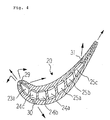
- Fig. 4 is a cross sectional view taken on line B-B of Fig. 3.
- a portion of the cooling air 40 in the cooling passage 23a on the blade leading edge side flows out of the blade through cooling holes 29 to effect a shower head film cooling for cooling of the blade leading edge portion.
- a portion of the cooling air 41 flowing through the cooling passage 24c flows out obliquely through cooling holes 30 to effect a film cooling of the blade surface.
- a portion of the cooling air 42, 43 flowing through the cooling passage 25c flows out of the blade surface obliquely through cooling holes 31 to effect a film cooling of the blade trailing edge portion.
- the cooling holes 29, 30, 31 only are illustrated in the figure, there are provided actually a multiplicity of cooling holes in the blade other than those mentioned here.
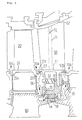
- Fig. 5 is an explanatory view showing flow of sealing air in a gas turbine in the prior art.
- a stationary blade 50 is arranged in a rear stage of the moving blade 20.
- Numeral 51 designates an inner shroud and
- numeral 52 designates an outer shroud.
- Numeral 53 designates a cavity, which is formed on an inner side of an end portion of the inner shroud 51 and
- numeral 54 designates a seal holding ring, which holds a labyrinth seal 58.
- the labyrinth seal 58 together with a rotor disc 80 forms a seal portion.
- Numeral 55 designates a hole, which is bored in the seal holding ring 54 and through which sealing air flows out, as described later.
- Numeral 56 designates a space, which is formed by and between the mutually adjacent moving blade 20 and stationary blade 50
- numeral 57 designates a honeycomb seal, which is provided at a front end portion of the inner shroud 51 of the stationary blade 50
- numeral 59 designates a space, which is formed by and between the stationary blade 50 and a rear stage moving blade adjacent thereto.
- sealing air 70 entering a sealing air tube 71 provided in the stationary blade 50 flows into the cavity 53 formed on the inner side of the inner shroud 51 to elevate pressure therein higher than that in a combustion gas path outside thereof and flows out through the hole 55 of the seal holding ring 54 to flow into the space 56 and then passes through a gap of a seal portion formed by a rear end portion 22b of the platform 22 of the moving blade 20 and the honeycomb seal 57 of the front end portion 57a of the inner shroud 51 of the stationary blade 50 to flow out into the combustion gas path as sealing air 70a.
- a portion of the sealing air which has flown out of the hole 55 of the seal holding ring 54 passes through a gap of a seal portion formed by the labyrinth seal 58 and the rotor disc 80 to flow into the space 59 and then passes through a seal portion formed by a rear end portion 57b of the inner shroud 51 and a platform front end portion of the rear stage moving blade to flow out into the combustion gas path as sealing air 70b, like in the case of the front stage.
- the same seal structure is applied between the moving blade 20 and a front stage stationary blade thereof, that is, sealing air passes through a seal portion formed by a front end portion 22a of the platform 22 of the moving blade 20 and an inner shroud rear end portion of the front stage stationary blade and flows out into the combustion gas path as sealing air 70c.
- sealing air passes through a seal portion formed by a front end portion 22a of the platform 22 of the moving blade 20 and an inner shroud rear end portion of the front stage stationary blade and flows out into the combustion gas path as sealing air 70c.
- cooling air is led into the blade for cooling thereof and while the cooling air flows through cooling passages in the blade, it flows out of the blade surface through cooling holes to effect a shower head film cooling of the blade leading edge portion and a film cooling of the blade ventral and dorsal side portions.
- combustor outlet temperature of approximately 1150°C has been realized and moreover a plant comprising that of as high as 1300°C or more is being developed.
- the first stage moving blade is a portion that is highly exposed to the high temperature combustion gas, cooling of the blade needs to be done most efficiently and further improvement of the cooling structure is desired.
- the present invention provides the following means of (1) and (2).
- the cooling air passing through the first passage cools the blade leading edge portion which is exposed to the combustion gas of the highest temperature to be under the severe thermal influence and then flows out of the blade tip portion as it is, thereby the blade leading edge portion can be cooled effectively by the cold cooling air.
- the blade trailing edge portion is cooled first by the cold air, thereby the blade hub portion which receives the thermal influence to deteriorate the fatigue strength is cooled effectively so as to prevent deterioration of the fatigue strength.
- the cooling air partially flows out of the slotted portion provided in the blade trailing edge for cooling therearound and the remaining portion flows through the passage formed in the serpentine shape toward the blade leading edge side for cooling of the blade main portions and flows out of the blade tip portion.
- the seal portion is constructed by the knife edge provided on each end of the platform and the inner shroud end each of the front stage and rear stage stationary blades adjacent to the moving blade and the sealing air carries out a sealing with the effect of the knife edge, thereby the sealing pressure which is elevated enough can be obtained at this portion. Further, the sealing air after having passed through the seal portion flows in the serpentine form with less quantity of air leakage and with increased resistance of the flow passage by the serpentine shape, thereby the sealing performance can be enhanced.
- the sealing air flows out into the combustion gas path obliquely upwardly so as to go along the flow direction of combustion gas therein, thereby the sealing air flows out to strike the end portion of the platform of the moving blade and the inner shroud end of the stationary blade and the effect to cool these portions can be obtained as well.
- Fig. 1 is a cross sectional view of a gas turbine cooled moving blade of an embodiment according to the present invention.
- Fig. 2 is a cross sectional view taken on line A-A of Fig. 1.
- Fig. 3 is a cross sectional view of a gas turbine cooled moving blade in the prior art.
- Fig. 4 is a cross sectional view taken on line B-B of Fig. 3.
- Fig. 5 is an explanatory view showing flow of sealing air in a gas turbine in the prior art.
- FIG. 1 is a cross sectional view of a gas turbine cooled moving blade, especially as an example of a first stage moving blade, of an embodiment according to the present invention
- Fig. 2 is a cross sectional view taken on line A-A of Fig. 1.
- numeral 1 designates a moving blade and numeral 2 designates a platform thereof.
- Numerals 3, 4, 5 designate cooling passages, respectively, which are provided in a blade root portion 16 and into which cooling air supplied from rotor side is led.
- the cooling passage 3 communicates with a cooling passage 3a provided in the blade and the cooling passages 4, 5 join together in the blade root portion 16 to form a cooling passage 6. That is, as compared with the cooling passages 23 to 26 in the prior art shown in Fig. 3, the cooling passages 3 to 5 shown in Fig. 1 are made in a less number of pieces and also the flow passage of the cooling passages 4, 5 is throttled by a rib so as to adjust flow rate of air entering there.
- the cooling passage 6 is provided on a trailing edge side of the blade to communicate sequentially with cooling passages 6a, 6b, 6c, 6d, 6e provided in the blade so as to form a serpentine cooling passage.
- Numeral 7 designates a trailing edge of the blade and a multiplicity of slots 15 are provided there substantially along a turbine axial direction.
- Numeral 8 designates a multiplicity of oblique turbulators provided on inner walls of the cooling passages 6a to 6e.
- Numerals 9a, 9b designate a multiplicity of turbulators provided on an inner wall of the cooling passage 3a on a leading edge side of the blade.
- Numeral 10 designates an upper surface sloping portion of a front end portion 2a of the platform 2, which slopes upward so as to go along a gas flow direction in a gas path and forms a passage 17 between itself and an inner shroud rear end portion of a front stage stationary blade adjacent thereto.
- Numeral 11 designates a lower surface sloping portion of a rear end portion 2c of the platform 2, which slopes upward so as to go along the gas flow direction in the gas path and forms a passage 18 between itself and an inner shroud front end portion of a rear stage stationary blade adjacent thereto.
- Numerals 12a, 12b, 12c designate seal pins, respectively, which are provided for sealing a portion between the platform 2 of the moving blade 1 and a platform of a moving blade provided adjacently to the moving blade 1 in a turbine circumferential direction.
- Numerals 13, 14 designate knife edges, respectively.
- the knife edge 13 is provided on a front end lower portion 2b of the platform 2 adjacently to a seal portion of the front stage stationary blade so as to seal an inner side of that seal portion.
- the knife edge 14 is likewise provided on a rear end lower portion 2d of the platform 2 adjacently to a seal portion of the rear stage stationary blade so as to seal an inner side of that seal portion.
- Numerals 100, 101, 102 designate cooling air, respectively, which is supplied from the rotor side to enter the cooling passages 3, 4, 5, respectively.
- the moving blade 1 is applied to its surface by a TBC (thermal barrier coating), such as a ceramics coating, so as to stand a thermal influence of a high temperature combustion gas in the gas path.
- TBC thermal barrier coating
- the cooling air 100 entering the cooling passage 3 flows into the cooling passage 3a linearly and, while becoming turbulent by the turbulators 9a, 9b so as to enhance a heat transfer rate, cools a leading edge portion of the blade, which is exposed to a high temperature to be in the thermally severest state, and then flows out of a tip portion of the blade to flow into the combustion gas path.
- Remaining portion of the cooling air flowing through the cooling passage 6a turns at the blade tip portion to enter the cooling passage 6b to flow toward the platform 2 for cooling that portion of the blade and then turns below the platform 2 to enter the cooling passage 6c to flow therethrough and further through the cooling passages 6d and 6e, turning at the blade tip portion and below the platform 2, respectively, and flows outside of the blade tip portion.
- the cooling air 101, 102 so flows through the serpentine cooling passage comprising the cooling passages 6a, 6b, 6c, 6d, 6e, it becomes turbulent by the turbulators 8 provided obliquely for enhancement of the cooling effect and cools main portions of the blade and then flows out of the blade tip portion.
- the cooling air 101, 102 is led into the trailing edge side of the moving blade 1 so that a cold air may flow into a hub portion of the blade trailing edge portion or especially so that a fatigue strength against heat of the trailing edge hub portion may be enhanced and further as the cold air enters the cooling passage 6a first, slotted portion of the blade trailing edge 7 is cooled efficiently, the oblique turbulators 8 in the cooling passage 6a can be made less in the number of pieces than in other cooling passages and the cooling passage 6a itself can be made larger than other cooling passages. Also, in the moving blade 1 having the cooling system so constructed, the cooling holes 29, 30, 31 (Fig. 4) in the prior art become unnecessary and the shower head film cooling there becomes also unnecessary.
- the cooling air 100 flows linearly through the cooling passage 3a on the blade leading edge side, becoming turbulent by the turbulators 9a, 9b, to cool the blade leading edge portion only.
- the cooling air 101, 102 enters on the blade trailing edge side to flow through the serpentine cooling passage comprising the cooling passages 6a, 6b, 6c, 6d, 6e, becoming turbulent by the turbulators 8 provided obliquely therein, to cool those portions of the blade, hence the entire blade can be cooled with the enhanced cooling effect.
- the sealing air 103, 104 flows through the serpentine routes formed by the knife edges 13, 14 and the upper surface and lower surface sloping portions 10, 11 to flow out obliquely upwardly through the passages 17, 18, thereby the sealing performance is enhanced and also the front end portion 2a of the platform 2 of the moving blade 1 and the inner shroud front end portion of the adjacent rear stage stationary blade can be cooled as well.
Landscapes
- Engineering & Computer Science (AREA)
- Mechanical Engineering (AREA)
- General Engineering & Computer Science (AREA)
- Turbine Rotor Nozzle Sealing (AREA)
Priority Applications (3)
| Application Number | Priority Date | Filing Date | Title |
|---|---|---|---|
| JP10203189A JP2000034902A (ja) | 1998-07-17 | 1998-07-17 | ガスタービン冷却動翼 |
| EP99120722A EP1094200A1 (de) | 1998-07-17 | 1999-10-19 | Gekühlte Gasturbinenrotorschaufel |
| CA002287577A CA2287577A1 (en) | 1998-07-17 | 1999-10-22 | Gas turbine cooled moving blade |
Applications Claiming Priority (3)
| Application Number | Priority Date | Filing Date | Title |
|---|---|---|---|
| JP10203189A JP2000034902A (ja) | 1998-07-17 | 1998-07-17 | ガスタービン冷却動翼 |
| EP99120722A EP1094200A1 (de) | 1998-07-17 | 1999-10-19 | Gekühlte Gasturbinenrotorschaufel |
| CA002287577A CA2287577A1 (en) | 1998-07-17 | 1999-10-22 | Gas turbine cooled moving blade |
Publications (1)
| Publication Number | Publication Date |
|---|---|
| EP1094200A1 true EP1094200A1 (de) | 2001-04-25 |
Family
ID=27171066
Family Applications (1)
| Application Number | Title | Priority Date | Filing Date |
|---|---|---|---|
| EP99120722A Withdrawn EP1094200A1 (de) | 1998-07-17 | 1999-10-19 | Gekühlte Gasturbinenrotorschaufel |
Country Status (3)
| Country | Link |
|---|---|
| EP (1) | EP1094200A1 (de) |
| JP (1) | JP2000034902A (de) |
| CA (1) | CA2287577A1 (de) |
Cited By (8)
| Publication number | Priority date | Publication date | Assignee | Title |
|---|---|---|---|---|
| US7044710B2 (en) | 2001-12-14 | 2006-05-16 | Alstom Technology Ltd. | Gas turbine arrangement |
| EP1780380A2 (de) * | 2005-10-27 | 2007-05-02 | United Technologies Corporation | Gasturbinendichtung zwischen Lauf- und Leitschaufeln |
| US7510375B2 (en) | 2005-01-04 | 2009-03-31 | United Technologies Corporation | Method of coating and a shield for a component |
| US7690894B1 (en) * | 2006-09-25 | 2010-04-06 | Florida Turbine Technologies, Inc. | Ceramic core assembly for serpentine flow circuit in a turbine blade |
| CN102187061A (zh) * | 2009-03-19 | 2011-09-14 | 三菱重工业株式会社 | 燃气轮机 |
| CN106481366A (zh) * | 2015-08-28 | 2017-03-08 | 中航商用航空发动机有限责任公司 | 冷却叶片和燃气涡轮 |
| EP3521570A1 (de) * | 2018-02-05 | 2019-08-07 | United Technologies Corporation | Bauteil und zugehöriges gasturbinentriebwerk |
| CN113586251A (zh) * | 2021-07-22 | 2021-11-02 | 西安交通大学 | 一种燃气轮机冷却气流逐级利用的部件冷却-轮缘密封结构 |
Families Citing this family (4)
| Publication number | Priority date | Publication date | Assignee | Title |
|---|---|---|---|---|
| JP5490191B2 (ja) | 2012-07-19 | 2014-05-14 | 三菱重工業株式会社 | ガスタービン |
| JP5606648B1 (ja) | 2014-06-27 | 2014-10-15 | 三菱日立パワーシステムズ株式会社 | 動翼、及びこれを備えているガスタービン |
| CN109798153B (zh) * | 2019-03-28 | 2023-08-22 | 中国船舶重工集团公司第七0三研究所 | 一种应用于船用燃气轮机涡轮轮盘的冷却结构 |
| CN113623014B (zh) * | 2021-07-22 | 2023-04-14 | 西安交通大学 | 一种燃气轮机透平叶片-轮盘联合冷却结构 |
Citations (7)
| Publication number | Priority date | Publication date | Assignee | Title |
|---|---|---|---|---|
| US3609057A (en) * | 1970-06-15 | 1971-09-28 | United Aircraft Corp | Turbine coolant flow system |
| GB2250548A (en) * | 1990-12-06 | 1992-06-10 | Rolls Royce Plc | Cooled turbine aerofoil blade |
| US5738489A (en) * | 1997-01-03 | 1998-04-14 | General Electric Company | Cooled turbine blade platform |
| EP0864728A2 (de) * | 1997-03-11 | 1998-09-16 | Mitsubishi Heavy Industries, Ltd. | Kühlluftzufuhrsystem für die Schaufeln einer Gasturbine |
| DE19811294A1 (de) * | 1997-03-18 | 1998-09-24 | Mitsubishi Heavy Ind Ltd | Gasturbinen-Dichtungssystem zwischen Schaufelumhüllung und -plattform |
| EP0924383A2 (de) * | 1997-12-17 | 1999-06-23 | United Technologies Corporation | Turbinenschaufel mit Kühlung der Hinterkantenwurzel |
| WO1999050534A1 (en) * | 1998-03-27 | 1999-10-07 | Pratt & Whitney Canada Corp. | Deflector for controlling entry of cooling air leakage into the gaspath of a gas turbine engine |
-
1998
- 1998-07-17 JP JP10203189A patent/JP2000034902A/ja active Pending
-
1999
- 1999-10-19 EP EP99120722A patent/EP1094200A1/de not_active Withdrawn
- 1999-10-22 CA CA002287577A patent/CA2287577A1/en not_active Abandoned
Patent Citations (7)
| Publication number | Priority date | Publication date | Assignee | Title |
|---|---|---|---|---|
| US3609057A (en) * | 1970-06-15 | 1971-09-28 | United Aircraft Corp | Turbine coolant flow system |
| GB2250548A (en) * | 1990-12-06 | 1992-06-10 | Rolls Royce Plc | Cooled turbine aerofoil blade |
| US5738489A (en) * | 1997-01-03 | 1998-04-14 | General Electric Company | Cooled turbine blade platform |
| EP0864728A2 (de) * | 1997-03-11 | 1998-09-16 | Mitsubishi Heavy Industries, Ltd. | Kühlluftzufuhrsystem für die Schaufeln einer Gasturbine |
| DE19811294A1 (de) * | 1997-03-18 | 1998-09-24 | Mitsubishi Heavy Ind Ltd | Gasturbinen-Dichtungssystem zwischen Schaufelumhüllung und -plattform |
| EP0924383A2 (de) * | 1997-12-17 | 1999-06-23 | United Technologies Corporation | Turbinenschaufel mit Kühlung der Hinterkantenwurzel |
| WO1999050534A1 (en) * | 1998-03-27 | 1999-10-07 | Pratt & Whitney Canada Corp. | Deflector for controlling entry of cooling air leakage into the gaspath of a gas turbine engine |
Cited By (12)
| Publication number | Priority date | Publication date | Assignee | Title |
|---|---|---|---|---|
| US7044710B2 (en) | 2001-12-14 | 2006-05-16 | Alstom Technology Ltd. | Gas turbine arrangement |
| US7510375B2 (en) | 2005-01-04 | 2009-03-31 | United Technologies Corporation | Method of coating and a shield for a component |
| US7939135B2 (en) | 2005-01-04 | 2011-05-10 | United Technologies Corporation | Method of shielding and coating an airfoil |
| EP1780380A2 (de) * | 2005-10-27 | 2007-05-02 | United Technologies Corporation | Gasturbinendichtung zwischen Lauf- und Leitschaufeln |
| EP1780380A3 (de) * | 2005-10-27 | 2011-07-20 | United Technologies Corporation | Gasturbinendichtung zwischen Lauf- und Leitschaufeln |
| US7690894B1 (en) * | 2006-09-25 | 2010-04-06 | Florida Turbine Technologies, Inc. | Ceramic core assembly for serpentine flow circuit in a turbine blade |
| CN102187061A (zh) * | 2009-03-19 | 2011-09-14 | 三菱重工业株式会社 | 燃气轮机 |
| CN102187061B (zh) * | 2009-03-19 | 2015-11-25 | 三菱日立电力系统株式会社 | 燃气轮机 |
| CN106481366A (zh) * | 2015-08-28 | 2017-03-08 | 中航商用航空发动机有限责任公司 | 冷却叶片和燃气涡轮 |
| EP3521570A1 (de) * | 2018-02-05 | 2019-08-07 | United Technologies Corporation | Bauteil und zugehöriges gasturbinentriebwerk |
| CN113586251A (zh) * | 2021-07-22 | 2021-11-02 | 西安交通大学 | 一种燃气轮机冷却气流逐级利用的部件冷却-轮缘密封结构 |
| CN113586251B (zh) * | 2021-07-22 | 2023-03-14 | 西安交通大学 | 一种燃气轮机冷却气流逐级利用的部件冷却-轮缘密封结构 |
Also Published As
| Publication number | Publication date |
|---|---|
| JP2000034902A (ja) | 2000-02-02 |
| CA2287577A1 (en) | 2001-04-22 |
Similar Documents
| Publication | Publication Date | Title |
|---|---|---|
| US7841828B2 (en) | Turbine airfoil with submerged endwall cooling channel | |
| KR101378252B1 (ko) | 터빈 블레이드, 터빈 로터, 및 가스 터빈 에어포일을냉각시키기 위한 방법 | |
| US7766606B2 (en) | Turbine airfoil cooling system with platform cooling channels with diffusion slots | |
| US5609466A (en) | Gas turbine vane with a cooled inner shroud | |
| US7510367B2 (en) | Turbine airfoil with endwall horseshoe cooling slot | |
| US6779597B2 (en) | Multiple impingement cooled structure | |
| US7632062B2 (en) | Turbine rotor blades | |
| US6354797B1 (en) | Brazeless fillet turbine nozzle | |
| US6506013B1 (en) | Film cooling for a closed loop cooled airfoil | |
| JP5898898B2 (ja) | タービンロータブレードのプラットフォーム領域を冷却するための装置及び方法 | |
| US6422817B1 (en) | Cooling circuit for and method of cooling a gas turbine bucket | |
| EP1284338A2 (de) | Kühleinsatz mit tangentialer Ausströmung | |
| JP2006083859A (ja) | タービンの動翼プラットフォームを冷却する装置および方法 | |
| US20070253815A1 (en) | Cooled gas turbine aerofoil | |
| US6468031B1 (en) | Nozzle cavity impingement/area reduction insert | |
| JP6184035B2 (ja) | 鋳造されたプラットフォーム冷却回路を有するタービン翼形部 | |
| US8172504B2 (en) | Hybrid impingement cooled airfoil | |
| JP2001073704A (ja) | 冷却先端動翼 | |
| JP2005299638A (ja) | 熱シールド型タービン翼形部 | |
| JP2010031865A (ja) | ロータブレード及びそれを製作する方法 | |
| JP2012102726A (ja) | タービンロータブレードのプラットフォーム領域を冷却するための装置、システム、及び方法 | |
| JP6010295B2 (ja) | タービンロータブレードのプラットフォーム領域を冷却するための装置及び方法 | |
| US8641377B1 (en) | Industrial turbine blade with platform cooling | |
| JP2006125402A (ja) | ガスタービンロータブレード | |
| US8366393B2 (en) | Rotor blade |
Legal Events
| Date | Code | Title | Description |
|---|---|---|---|
| PUAI | Public reference made under article 153(3) epc to a published international application that has entered the european phase |
Free format text: ORIGINAL CODE: 0009012 |
|
| 17P | Request for examination filed |
Effective date: 19991116 |
|
| AK | Designated contracting states |
Kind code of ref document: A1 Designated state(s): CH DE FR GB IT LI |
|
| AX | Request for extension of the european patent |
Free format text: AL;LT;LV;MK;RO;SI |
|
| AKX | Designation fees paid |
Free format text: CH DE FR GB IT LI |
|
| 17Q | First examination report despatched |
Effective date: 20030923 |
|
| STAA | Information on the status of an ep patent application or granted ep patent |
Free format text: STATUS: THE APPLICATION IS DEEMED TO BE WITHDRAWN |
|
| 18D | Application deemed to be withdrawn |
Effective date: 20040204 |