EP1093884B1 - A shift device for wheel head of sander - Google Patents
A shift device for wheel head of sander Download PDFInfo
- Publication number
- EP1093884B1 EP1093884B1 EP19990123775 EP99123775A EP1093884B1 EP 1093884 B1 EP1093884 B1 EP 1093884B1 EP 19990123775 EP19990123775 EP 19990123775 EP 99123775 A EP99123775 A EP 99123775A EP 1093884 B1 EP1093884 B1 EP 1093884B1
- Authority
- EP
- European Patent Office
- Prior art keywords
- wheel head
- output shaft
- hole
- slot
- shift device
- Prior art date
- Legal status (The legal status is an assumption and is not a legal conclusion. Google has not performed a legal analysis and makes no representation as to the accuracy of the status listed.)
- Expired - Lifetime
Links
- 239000004744 fabric Substances 0.000 description 3
- 230000001681 protective effect Effects 0.000 description 1
- 239000004576 sand Substances 0.000 description 1
Images


Classifications
-
- B—PERFORMING OPERATIONS; TRANSPORTING
- B24—GRINDING; POLISHING
- B24B—MACHINES, DEVICES, OR PROCESSES FOR GRINDING OR POLISHING; DRESSING OR CONDITIONING OF ABRADING SURFACES; FEEDING OF GRINDING, POLISHING, OR LAPPING AGENTS
- B24B23/00—Portable grinding machines, e.g. hand-guided; Accessories therefor
- B24B23/04—Portable grinding machines, e.g. hand-guided; Accessories therefor with oscillating grinding tools; Accessories therefor
-
- B—PERFORMING OPERATIONS; TRANSPORTING
- B24—GRINDING; POLISHING
- B24B—MACHINES, DEVICES, OR PROCESSES FOR GRINDING OR POLISHING; DRESSING OR CONDITIONING OF ABRADING SURFACES; FEEDING OF GRINDING, POLISHING, OR LAPPING AGENTS
- B24B45/00—Means for securing grinding wheels on rotary arbors
Definitions
- the present invention relates to electric tools, and more particularly to a shift device for a wheel head of a sander.
- a sander is an electric tool which, when it is put in operation, is driven by means of an electric motor, and its eccentric mechanism drives the wheel head of the sander to work via transferring mechanism to sand the workpieces for example by means of an abrasive cloth.
- the wheel head of the sander is connected to the sander via support in a hoisting manner, and the output shaft of the eccentric mechanism is connected and fixed to the wheel head of the sander.
- the users have to shift various wheel heads having different shapes according to the shapes of workpieces and the various actual circumstances.
- the objective of the present invention is to provide a shift device for a wheel head of sander capable of shifting or exchanging the wheel head of a sander quickly, which can improve the work efficiency and is very convenient to the end user.
- a shift device for a wheel head of a sander comprising an output shaft and a wheel head, is charactrized by a latching device which is located in the output shaft and which is actuable to a retracted position in which it is disposed within the output shaft and to an extended position in which it extends beyond the periphery of the output shaft and into a recess in the wheel head.
- the shift device is characterized in that said output shaft is inserted into a connecting hole of said wheel head; a hole is located in the center part of said output shaft and a slot is positioned at the end of said output shaft; a spring and a latch axis are disposed in said hole; two fix latches are disposed in said slot, said two latches stretch towards two sides of said slot and are inserted into a slot which is located on the wall of said connecting hole, said latch axis is connected with said two fix latches via a pin.
- the shift device is characterized in that said device further comprises: a polygonal blind hole located on said wheel head; a bed plate, the external shape of said bed plate matching with said polygonal blind hole; four positioning holes located on said bed plate; a front support and a rear support being inserted into said positioning holes respectively and fixed by screws passing through said positioning holes; a slot located at the upper part of said front support; a slot located at the upper part of said rear support; ribbed slabs with concave located on a left shell and a right shell; said front support and rear support being inserted into said ribbed slabs of said left shell and right shell respectively, said front support and rear support being assembled and fixed by said right shell and left shell respectively.
- This embodiment of the shift device is specially advantageous for a reciprocating wheel head of a sander.
- the shift device is characterized in that said wheel head has a blind hole with its diameter larger than the outline of the bed plate, and a transferring mechanism between the wheel head and the output shaft.
- This embodiment of the shift device is specially advantageous for a rotatable wheel head of a sander.
- the shift device is charactrerized by a waist shaped hole located in the middle of said wheel head, and a waist shaped shoulder matching with said waist shaped hole located at the lower part of said output shaft.
- the swirling action of said output shaft can be transferred to said wheel head in an advantageous manner by way of the coordination of said waist shaped hole and said waist shaped shoulder.
- the shift device is charactrerized by an adjusting screw, said adjusting screw being connected with the upper part of said hole via screw, a restricting sleeve disposed in said hole, and the lower part of said restricting sleeve being put on the top surface of said fix latches. It is possible in the embodiment to adjust the latching device in an easy way.
- the shift device is charactrerized by a ladder surface located on the outer surface of said latch axis, the upper part of said ladder surface being larger than the lower part of said ladder surface; and a ladder surface corresponding to the outer surface of said latch axis being located in said hole. Said latch axis will not fall off from the output shaft due to the special structure of ladder surface.
- the wheel head is fixed at the end of the output shaft by two fix latches and a spring is disposed in the hole of the output shaft.
- the spring presses the upper part of the latch axis to force the two ends of the two fix latches raised upward.
- said restricting sleeve presses the top surface of the fix latches, and the height of the fix latches can be adjusted via adjusting screw.
- the latch axis is pressed at the upper portion by the spring, and supported at the lower portion by ladder, so the latch axis will not fall off from the hole of said output shaft and the fix latch will not rotate upward and thus goes into said concave slot either.
- the shift device for reciprocal wheel head of sander of the present invention there are front and rear supports disposed on the bed plate to restrict the wheel head, and to restrict the wheel head to move in a reciprocating manner.
- the wheel head is disconnected with the bed plate. As a result, the wheel head does not contact the bed plate during the rotary motion.
- the shift device for a wheel head of a sander of the present invention comprises an output shaft 1 and a wheel head 2.
- the output shaft 1 is inserted into a connecting hole 3 of the wheel head 2 and it is connected with a chuck 33 through a ball bearing 35.
- a hole 4 is located in the center part of the output shaft 1, and a slot 5 is located in the center part of the output shaft 1.
- a spring 6 and a latch axis 7 are disposed in the hole 4, stretching toward two sides.
- Two fix latches 8 are disposed in the slot 5 and the other end of the fix latch 8 is inserted in the slot 9 which is located on the wall of the connecting hole 3.
- the latch axis 7 is connected to the fix latch 8 via a pin 10.
- FIG. 1 shows the manner the front support 19 and the rear support 20 to be assembled and fixed.
- a thread hole is located on the upper part of the hole 4, an adjusting screw 11 is mounted in the thread hole, a restricting sleeve 12 is disposed in the hole 4 below the adjusting screw 11.
- the lower part of the restricting sleeve 12 is abutting the upper part of the fix latches 8.
- a slot 13 is located at the lower part of the latch axis 7, and the two fix latches are inserted into the slot 5 and the slot 13.
- These two fix latches 8 are connected to the latch axis 7 via the pin 10.
- An end cover 14 is positioned at the lower part of the latch axis 7.
- a ladder surface is located on the outer surface of the latch axis 7, and the upper diameter of the ladder surface is larger than the lower diameter of the ladder surface.
- a corresponding ladder surface is located in the hole 4 which is located at the lower part of the output shaft 1.
- the chuck 33 rotates about the centerline 34 of electric tools instrument. Owing to the polygonal blind hole 16 restricted by corresponding polygonal external shape of the bed plate 17, the wheel head 2 is grasped by the fix latch 8. Therefore, when the chuck 33 rotates, due to the eccentricity ⁇ existed between the centerline 34 and centerline 31, the output shaft 1 moves reciprocally within reciprocal scope of 2 ⁇ .
- Figures 3 and 4 show a shift device for rotatable wheel head of a sander of the present invention.
- the basic structure of it is almost the same as that of the device for the reciprocal wheel head.
- the differences between the shift device for rotary wheel head of sander from the shift device for reciprocal wheel head are as follows.
- a blind hole 28 is located on a wheel 27, the diameter of the blind hole 28 is larger than the external diameter of the bed plate 17, and a driven device is disposed between the wheel head 27 and the output shaft 1.
- the waist hole 29 of the wheel head 27 matches with the waist shoulder 30 of the output shaft 1 to enable the output shaft 1 to drive the wheel head 27 into motion.
- the output shaft 1 When the device is put in operation, the chuck 33 rotates about the centerline 34, owing to the eccentricity ⁇ exists between centerline 34 and centerline 31, the output shaft 1 is driven into motion. Since the diameter of the blind hole 28 on wheel head 27 is larger than the external size of the bed plate 17, and the tolerance dl between the external diameter of the center part of wheel head 27 and the hole of the bed plate 17 is bigger than the eccentricity ⁇ , the output shaft 1 may rotate freely. The shoulder is inserted into the hole 29, and brings the wheel head 27 into eccentric rotary motion against the centerline 34.
Landscapes
- Engineering & Computer Science (AREA)
- Mechanical Engineering (AREA)
- Finish Polishing, Edge Sharpening, And Grinding By Specific Grinding Devices (AREA)
- Grinding Of Cylindrical And Plane Surfaces (AREA)
Description
- The present invention relates to electric tools, and more particularly to a shift device for a wheel head of a sander.
- A sander is an electric tool which, when it is put in operation, is driven by means of an electric motor, and its eccentric mechanism drives the wheel head of the sander to work via transferring mechanism to sand the workpieces for example by means of an abrasive cloth.
- In prior art, the wheel head of the sander is connected to the sander via support in a hoisting manner, and the output shaft of the eccentric mechanism is connected and fixed to the wheel head of the sander. During the operation, however, the users have to shift various wheel heads having different shapes according to the shapes of workpieces and the various actual circumstances.
- To shift or exchange the wheel head in prior art is diverse and complicated. It is necessary to loosen fixed screw which fixes the wheel head to the support and the output shaft, and then to fetch out the wheel head to shift the wheel head. This is very inconvenient to the users and the work efficiency is much lower.
- The objective of the present invention is to provide a shift device for a wheel head of sander capable of shifting or exchanging the wheel head of a sander quickly, which can improve the work efficiency and is very convenient to the end user.
- The achieve this objective, a shift device for a wheel head of a sander, said device comprising an output shaft and a wheel head, is charactrized by a latching device which is located in the output shaft and which is actuable to a retracted position in which it is disposed within the output shaft and to an extended position in which it extends beyond the periphery of the output shaft and into a recess in the wheel head.
- According to a preferred embodiment of the invention, the shift device is characterized in that said output shaft is inserted into a connecting hole of said wheel head; a hole is located in the center part of said output shaft and a slot is positioned at the end of said output shaft; a spring and a latch axis are disposed in said hole; two fix latches are disposed in said slot, said two latches stretch towards two sides of said slot and are inserted into a slot which is located on the wall of said connecting hole, said latch axis is connected with said two fix latches via a pin.
- According to a preferred embodiment of the invention, the shift device is characterized in that said device further comprises: a polygonal blind hole located on said wheel head; a bed plate, the external shape of said bed plate matching with said polygonal blind hole; four positioning holes located on said bed plate; a front support and a rear support being inserted into said positioning holes respectively and fixed by screws passing through said positioning holes; a slot located at the upper part of said front support; a slot located at the upper part of said rear support; ribbed slabs with concave located on a left shell and a right shell; said front support and rear support being inserted into said ribbed slabs of said left shell and right shell respectively, said front support and rear support being assembled and fixed by said right shell and left shell respectively. This embodiment of the shift device is specially advantageous for a reciprocating wheel head of a sander.
- According to a preferred embodiment of the invention, the shift device is characterized in that said wheel head has a blind hole with its diameter larger than the outline of the bed plate, and a transferring mechanism between the wheel head and the output shaft. This embodiment of the shift device is specially advantageous for a rotatable wheel head of a sander.
- According to a preferred embodiment of the invention, the shift device is charactrerized by a waist shaped hole located in the middle of said wheel head, and a waist shaped shoulder matching with said waist shaped hole located at the lower part of said output shaft. The swirling action of said output shaft can be transferred to said wheel head in an advantageous manner by way of the coordination of said waist shaped hole and said waist shaped shoulder.
- According to a preferred embodiment of the invention, the shift device is charactrerized by an adjusting screw, said adjusting screw being connected with the upper part of said hole via screw, a restricting sleeve disposed in said hole, and the lower part of said restricting sleeve being put on the top surface of said fix latches. It is possible in the embodiment to adjust the latching device in an easy way.
- According to a preferred embodiment of the invention, the shift device is charactrerized by a ladder surface located on the outer surface of said latch axis, the upper part of said ladder surface being larger than the lower part of said ladder surface; and a ladder surface corresponding to the outer surface of said latch axis being located in said hole. Said latch axis will not fall off from the output shaft due to the special structure of ladder surface.
- According to the preferred embodiment of the invention, the wheel head is fixed at the end of the output shaft by two fix latches and a spring is disposed in the hole of the output shaft. The spring presses the upper part of the latch axis to force the two ends of the two fix latches raised upward. On the other hand, said restricting sleeve presses the top surface of the fix latches, and the height of the fix latches can be adjusted via adjusting screw.
- According to the preferred embodiment of the shift the latch axis is pressed at the upper portion by the spring, and supported at the lower portion by ladder, so the latch axis will not fall off from the hole of said output shaft and the fix latch will not rotate upward and thus goes into said concave slot either.
- In the case of the shift device for reciprocal wheel head of sander of the present invention, there are front and rear supports disposed on the bed plate to restrict the wheel head, and to restrict the wheel head to move in a reciprocating manner. In the case of shift device for rotatable wheel head of sander of the present invention, the wheel head is disconnected with the bed plate. As a result, the wheel head does not contact the bed plate during the rotary motion.
- When the wheel head is to be shifted, the lower end of the latch axis is lifted upward under the action of the restricting sleeve, the fix latch is rotated downward and goes into the concave slot As a result, the wheel head is retrieved from the output shaft, and quick mounting and dismounting operation of the shift device for wheel head of sander is achieved.
- Further preferred embodiments of the invention and the features thereof are given in the appended claims and sub-claims.
- Preferred embodiments of the invention will now be described in detail in conjunction with the accompanying drawings in which:
- Figure 1
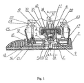
- is a view showing the reciprocal wheel head of a sander;
- Figure 2
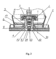
- is the A-A cutaway view of Figure 1;
- Figure 3
- is a view showing the rotatable wheel head of a sander,
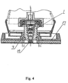
- Figure 4
- is the B-B cutaway view of Figure 3;
- Figure 5
- is the view taken from Figure 2 showing the manner of mounting the left and right supports; and
- Figure 6
- is the C-C cutaway view of Figure 4.
- Referring to Figure 1 and Figure 2, the shift device for a wheel head of a sander of the present invention comprises an
output shaft 1 and awheel head 2. Theoutput shaft 1 is inserted into a connectinghole 3 of thewheel head 2 and it is connected with achuck 33 through a ball bearing 35. Ahole 4 is located in the center part of theoutput shaft 1, and a slot 5 is located in the center part of theoutput shaft 1. Aspring 6 and alatch axis 7 are disposed in thehole 4, stretching toward two sides. Twofix latches 8 are disposed in the slot 5 and the other end of thefix latch 8 is inserted in theslot 9 which is located on the wall of the connectinghole 3. Thelatch axis 7 is connected to thefix latch 8 via apin 10. - Besides, there is a polygonal
blind hole 16 located on thewheel head 2, the external shape of thebed plate 17 matches with the shape of the polygonal thehole 16. Aprotective sleeve 32 is disposed at the upper part of thebed plate 17, and fourpositioning holes 18 are located on thebed plate 17. The lower parts of thefront support 19 and therear support 20 are inserted into thepositioning holes 18 to the fix thefront support 19 and therear support 20 to thebed plate 17 by self-driven screws 21. Aslot 22 is located at the upper part of thefront support 19 and aslot 23 is located at the upper part of therear support 23. The ribbedslabs 25 are located on theleft shell 24 andright shell 26 respectively, thefront support 19 and therear support 20 are inserted into the ribbedslab 25 respectively. Figure 5 shows the manner thefront support 19 and therear support 20 to be assembled and fixed. - Referring to Figures 1 and 2, a thread hole is located on the upper part of the
hole 4, an adjusting screw 11 is mounted in the thread hole, a restrictingsleeve 12 is disposed in thehole 4 below the adjusting screw 11. The lower part of the restrictingsleeve 12 is abutting the upper part of thefix latches 8. Aslot 13 is located at the lower part of thelatch axis 7, and the two fix latches are inserted into the slot 5 and theslot 13. These twofix latches 8 are connected to thelatch axis 7 via thepin 10. Anend cover 14 is positioned at the lower part of thelatch axis 7. - A ladder surface is located on the outer surface of the
latch axis 7, and the upper diameter of the ladder surface is larger than the lower diameter of the ladder surface. A corresponding ladder surface is located in thehole 4 which is located at the lower part of theoutput shaft 1. - When the shift device is put in operation, the
chuck 33 rotates about thecenterline 34 of electric tools instrument. Owing to the polygonalblind hole 16 restricted by corresponding polygonal external shape of thebed plate 17, thewheel head 2 is grasped by thefix latch 8. Therefore, when thechuck 33 rotates, due to the eccentricity δ existed between thecenterline 34 andcenterline 31, theoutput shaft 1 moves reciprocally within reciprocal scope of 2δ. - Whenever the
wheel head 2 is to be shifted, referring to Figure 1, the abrasive cloth 36 is torn from thewheel head 2, theend cover 14 is lifted upward, and then thefix latch 8 will be retrieved from theconcave slot 9 into the slot 5 of theoutput shaft 1 and thewheel head 2 will be fetched out. - Figures 3 and 4 show a shift device for rotatable wheel head of a sander of the present invention. The basic structure of it is almost the same as that of the device for the reciprocal wheel head. The differences between the shift device for rotary wheel head of sander from the shift device for reciprocal wheel head are as follows. According to the shift device for rotatable wheel head of sander of the present invention, a
blind hole 28 is located on awheel 27, the diameter of theblind hole 28 is larger than the external diameter of thebed plate 17, and a driven device is disposed between thewheel head 27 and theoutput shaft 1. Referring to Figure 6, thewaist hole 29 of thewheel head 27 matches with thewaist shoulder 30 of theoutput shaft 1 to enable theoutput shaft 1 to drive thewheel head 27 into motion. - When the device is put in operation, the
chuck 33 rotates about thecenterline 34, owing to the eccentricity δ exists betweencenterline 34 andcenterline 31, theoutput shaft 1 is driven into motion. Since the diameter of theblind hole 28 onwheel head 27 is larger than the external size of thebed plate 17, and the tolerance dl between the external diameter of the center part ofwheel head 27 and the hole of thebed plate 17 is bigger than the eccentricity δ, theoutput shaft 1 may rotate freely. The shoulder is inserted into thehole 29, and brings thewheel head 27 into eccentric rotary motion against thecenterline 34. - When the
wheel head 27 is to be shifted, the abrasive cloth 36 is torn from thewheel head 27, theend cover 14 is lifted upward, thefix latch 8 will be retrieved from theconcave slot 9 into the slot 5 of theoutput shaft 1. Then, thewheel head 27 will be fetched out
Claims (10)
- A shift device for a wheel head of a sander, said device comprising an output shaft and a wheel head, characterized by a latching device (6,7,8) which is located in the output shaft (1) and which is actuable to a retracted position in which it is disposed within the output shaft (1) and to an extended position in which it extends beyond the periphery of the output shaft (1) and into a recess (9) in the wheel head (2).
- A shift device as claimed in claim 1, characterized in that said output shaft(1) is inserted into a connecting hole (3) of said wheel head (2); a hole (4) is located in the center of said output shaft (1) and a slot (5) is positioned at the end of said output shaft (1); a spring (6) and a latch axis (7) are disposed in said hole (4); two the fix latches (8) are disposed in said slot (5), said two fix latches (8) stretch towards two sides of said slot (5) and are inserted into a slot (9) which is located on the wall of said connecting hole (3), said latch axis (7) is connected with said two fix latches (8) via a pin (10).
- A shift device as claimed in claim 1 or 2, characterized in that said device further comprises a polygonal blind hole (16) located on said wheel head (2); a bed plate (17), the external shape of said bed plate (17) matching with said polygonal blind hole (16); four positioning holes (18) located on said bed plate (17); a front support (19) and a rear support (20) being inserted into said positioning holes (18) respectively and fixed by screws (21) passing through said positioning holes (18); a slot (22) located at the upper part of said front support (19); a slot (23) located at the upper part of said rear support (20); ribbed slabs (25) with concave located on a left shell (24) and a right shell (26); said front support (19) and rear support (20) being inserted into said ribbed slabs (25) of said left shell (24) and right shell (26) respectively, said front support (19) and rear support (20) being assembled and fixed by said right shell (26) and left shell (24) respectively.
- A shift device as claimed in claim 1 or 2, further characterized by a blind hole (28) disposed on a wheel head (27), the diameter of said blind hole (28) being larger than the external size of the bed plate (17); a driven device disposed between said wheel head (27) and said output shaft (1).
- A shift device as claimed in claim 4, characterized in that a waist shaped hole (29) is located in the middle of said wheel head (27), and a waist shaped shoulder (30) matching with said waist shaped hole (29) is located at the lower part of said output shaft (1).
- A shift device as claimed in any of the preceding claims, further characterized by an adjusting screw (11), said adjusting screw (11) being connected with the upper part of said hole (4) via screw; a restricting sleeve (12) disposed in said hole (4), and the lower part of said restricting sleeve (12) being put on the top surface of said fix latches (8).
- A shift device as claimed in any of the preceding claims, further characterized by a slot (13) located at the lower part of said latch axis (7), said two fix latches (8) being inserted into said slot (5) and said slot (13) and connected with said latch axis (7) via a pin (10).
- A shift device as claimed in claim 7, characterized in that an end cover (14) is positioned at the lower part of said latch axis (7).
- A shift device as claimed in any of the preceding claims, further characterized in that a restricting device is disposed between the outer surface of the latch axis (7) and said hole (4) which is located at the lower part of said output shaft (1).
- A shift device as claimed in claim 9, characterized in that said restricting device comprises a ladder surface (15) located on the outer surface of said latch axis (7), the upper part of said ladder surface (15) being larger than the lower part of said ladder surface(15); and a ladder surface (15) corresponding to the outer surface of said latch axis (7) being made on said hole (4).
Applications Claiming Priority (2)
| Application Number | Priority Date | Filing Date | Title |
|---|---|---|---|
| CN99239991 | 1999-10-20 | ||
| CN99239991U CN2392638Y (en) | 1999-10-20 | 1999-10-20 | Device for quickly changing grinding head of disk sander |
Publications (3)
| Publication Number | Publication Date |
|---|---|
| EP1093884A2 EP1093884A2 (en) | 2001-04-25 |
| EP1093884A3 EP1093884A3 (en) | 2002-10-16 |
| EP1093884B1 true EP1093884B1 (en) | 2003-06-04 |
Family
ID=5316151
Family Applications (1)
| Application Number | Title | Priority Date | Filing Date |
|---|---|---|---|
| EP19990123775 Expired - Lifetime EP1093884B1 (en) | 1999-10-20 | 1999-11-30 | A shift device for wheel head of sander |
Country Status (3)
| Country | Link |
|---|---|
| EP (1) | EP1093884B1 (en) |
| CN (1) | CN2392638Y (en) |
| DE (1) | DE69908597T2 (en) |
Cited By (1)
| Publication number | Priority date | Publication date | Assignee | Title |
|---|---|---|---|---|
| CN1939665B (en) * | 2005-09-30 | 2010-10-13 | 苏州宝时得电动工具有限公司 | Surface treater |
Families Citing this family (2)
| Publication number | Priority date | Publication date | Assignee | Title |
|---|---|---|---|---|
| DE10160265A1 (en) | 2001-12-07 | 2003-06-18 | Bosch Gmbh Robert | Hand orbital sander |
| CN114589365A (en) * | 2022-04-21 | 2022-06-07 | 河南航天液压气动技术有限公司 | Light-load working condition floating adjusting device |
Family Cites Families (2)
| Publication number | Priority date | Publication date | Assignee | Title |
|---|---|---|---|---|
| US4045038A (en) * | 1976-08-31 | 1977-08-30 | Westvaco Corporation | Hollow core chucking device |
| US4850734A (en) * | 1988-12-23 | 1989-07-25 | United Technologies Corporation | Coupling device for a machine tool |
-
1999
- 1999-10-20 CN CN99239991U patent/CN2392638Y/en not_active Expired - Fee Related
- 1999-11-30 DE DE69908597T patent/DE69908597T2/en not_active Expired - Fee Related
- 1999-11-30 EP EP19990123775 patent/EP1093884B1/en not_active Expired - Lifetime
Cited By (1)
| Publication number | Priority date | Publication date | Assignee | Title |
|---|---|---|---|---|
| CN1939665B (en) * | 2005-09-30 | 2010-10-13 | 苏州宝时得电动工具有限公司 | Surface treater |
Also Published As
| Publication number | Publication date |
|---|---|
| DE69908597D1 (en) | 2003-07-10 |
| EP1093884A2 (en) | 2001-04-25 |
| DE69908597T2 (en) | 2004-04-29 |
| EP1093884A3 (en) | 2002-10-16 |
| CN2392638Y (en) | 2000-08-23 |
Similar Documents
| Publication | Publication Date | Title |
|---|---|---|
| US6264211B1 (en) | Reciprocating saw attachment for electric drill | |
| JPH08309654A (en) | Sanding tool | |
| KR20090041444A (en) | Lockable and dual actuation head assembly in random orbit | |
| CN113043133B (en) | Polishing tool | |
| KR100443733B1 (en) | Chuck device | |
| CN101856811A (en) | Portable Corner Impact Tool | |
| EP1093884A2 (en) | A shift device for wheel head of sander | |
| CN114888680B (en) | Quick-change bottom plate of sander and multifunctional sander | |
| CN217750699U (en) | Centerless grinding machine with improved adjusting wheel | |
| CN111975476A (en) | Pipe surface polishing processing device | |
| US5335560A (en) | Table-top grinder power transmission mechanism | |
| CN212763909U (en) | Press lock shaft type electric wood milling machine | |
| US5402605A (en) | Oscillating sander | |
| CN210968406U (en) | Grinding main shaft for coarse grinding and accurate grinding integrated machine of crystal silicon | |
| CN201151078Y (en) | Polishers | |
| WO2006043170A3 (en) | A machining head for machine tools with a shaft with low thermal expansion coefficient | |
| CN101163570B (en) | Sanding pad lock for sander | |
| CN217530357U (en) | Flat head angle grinder | |
| CN111469221A (en) | Electric wood milling machine and using method thereof | |
| RU2106234C1 (en) | Bench-type grinder | |
| US20040087260A1 (en) | Sand-belt finishing machine having a reciprocal movement mechanism | |
| CN214980093U (en) | a polishing machine | |
| US6511366B1 (en) | Rotary woodworking machine | |
| CN102689262B (en) | Sanding working head and sanding tool using same | |
| KR200280306Y1 (en) | Vertical sandpaper belt grinder with internal and external polishing |
Legal Events
| Date | Code | Title | Description |
|---|---|---|---|
| PUAI | Public reference made under article 153(3) epc to a published international application that has entered the european phase |
Free format text: ORIGINAL CODE: 0009012 |
|
| AK | Designated contracting states |
Kind code of ref document: A2 Designated state(s): AT BE CH CY DE DK ES FI FR GB GR IE IT LI LU MC NL PT SE |
|
| AX | Request for extension of the european patent |
Free format text: AL;LT;LV;MK;RO;SI |
|
| PUAL | Search report despatched |
Free format text: ORIGINAL CODE: 0009013 |
|
| AK | Designated contracting states |
Kind code of ref document: A3 Designated state(s): AT BE CH CY DE DK ES FI FR GB GR IE IT LI LU MC NL PT SE |
|
| AX | Request for extension of the european patent |
Free format text: AL;LT;LV;MK;RO;SI |
|
| RIC1 | Information provided on ipc code assigned before grant |
Free format text: 7B 24B 23/04 A, 7B 24B 45/00 B, 7B 24B 23/02 B, 7B 23B 31/40 B |
|
| GRAH | Despatch of communication of intention to grant a patent |
Free format text: ORIGINAL CODE: EPIDOS IGRA |
|
| 17P | Request for examination filed |
Effective date: 20020916 |
|
| GRAH | Despatch of communication of intention to grant a patent |
Free format text: ORIGINAL CODE: EPIDOS IGRA |
|
| GRAA | (expected) grant |
Free format text: ORIGINAL CODE: 0009210 |
|
| AK | Designated contracting states |
Designated state(s): DE FR GB NL |
|
| REG | Reference to a national code |
Ref country code: GB Ref legal event code: FG4D |
|
| AKX | Designation fees paid |
Designated state(s): DE FR GB NL |
|
| REG | Reference to a national code |
Ref country code: IE Ref legal event code: FG4D |
|
| REF | Corresponds to: |
Ref document number: 69908597 Country of ref document: DE Date of ref document: 20030710 Kind code of ref document: P |
|
| LTIE | Lt: invalidation of european patent or patent extension |
Effective date: 20030604 |
|
| PG25 | Lapsed in a contracting state [announced via postgrant information from national office to epo] |
Ref country code: GB Free format text: LAPSE BECAUSE OF NON-PAYMENT OF DUE FEES Effective date: 20031130 |
|
| ET | Fr: translation filed | ||
| PLBE | No opposition filed within time limit |
Free format text: ORIGINAL CODE: 0009261 |
|
| STAA | Information on the status of an ep patent application or granted ep patent |
Free format text: STATUS: NO OPPOSITION FILED WITHIN TIME LIMIT |
|
| 26N | No opposition filed |
Effective date: 20040305 |
|
| PG25 | Lapsed in a contracting state [announced via postgrant information from national office to epo] |
Ref country code: NL Free format text: LAPSE BECAUSE OF NON-PAYMENT OF DUE FEES Effective date: 20040601 |
|
| PG25 | Lapsed in a contracting state [announced via postgrant information from national office to epo] |
Ref country code: DE Free format text: LAPSE BECAUSE OF NON-PAYMENT OF DUE FEES Effective date: 20040602 |
|
| GBPC | Gb: european patent ceased through non-payment of renewal fee |
Effective date: 20031130 |
|
| NLV4 | Nl: lapsed or anulled due to non-payment of the annual fee |
Effective date: 20040601 |
|
| REG | Reference to a national code |
Ref country code: IE Ref legal event code: MM4A |
|
| PG25 | Lapsed in a contracting state [announced via postgrant information from national office to epo] |
Ref country code: FR Free format text: LAPSE BECAUSE OF NON-PAYMENT OF DUE FEES Effective date: 20031130 |
|
| REG | Reference to a national code |
Ref country code: FR Ref legal event code: ST Effective date: 20081020 |