EP1093552B1 - Arrangement and method for a driving unit in a vehicle - Google Patents
Arrangement and method for a driving unit in a vehicle Download PDFInfo
- Publication number
- EP1093552B1 EP1093552B1 EP99933400A EP99933400A EP1093552B1 EP 1093552 B1 EP1093552 B1 EP 1093552B1 EP 99933400 A EP99933400 A EP 99933400A EP 99933400 A EP99933400 A EP 99933400A EP 1093552 B1 EP1093552 B1 EP 1093552B1
- Authority
- EP
- European Patent Office
- Prior art keywords
- gearbox
- rotor machine
- engine
- connecting device
- designed
- Prior art date
- Legal status (The legal status is an assumption and is not a legal conclusion. Google has not performed a legal analysis and makes no representation as to the accuracy of the status listed.)
- Expired - Lifetime
Links
Images
Classifications
-
- B—PERFORMING OPERATIONS; TRANSPORTING
- B60—VEHICLES IN GENERAL
- B60K—ARRANGEMENT OR MOUNTING OF PROPULSION UNITS OR OF TRANSMISSIONS IN VEHICLES; ARRANGEMENT OR MOUNTING OF PLURAL DIVERSE PRIME-MOVERS IN VEHICLES; AUXILIARY DRIVES FOR VEHICLES; INSTRUMENTATION OR DASHBOARDS FOR VEHICLES; ARRANGEMENTS IN CONNECTION WITH COOLING, AIR INTAKE, GAS EXHAUST OR FUEL SUPPLY OF PROPULSION UNITS IN VEHICLES
- B60K6/00—Arrangement or mounting of plural diverse prime-movers for mutual or common propulsion, e.g. hybrid propulsion systems comprising electric motors and internal combustion engines
- B60K6/20—Arrangement or mounting of plural diverse prime-movers for mutual or common propulsion, e.g. hybrid propulsion systems comprising electric motors and internal combustion engines the prime-movers consisting of electric motors and internal combustion engines, e.g. HEVs
- B60K6/42—Arrangement or mounting of plural diverse prime-movers for mutual or common propulsion, e.g. hybrid propulsion systems comprising electric motors and internal combustion engines the prime-movers consisting of electric motors and internal combustion engines, e.g. HEVs characterised by the architecture of the hybrid electric vehicle
- B60K6/48—Parallel type
- B60K6/485—Motor-assist type
-
- B—PERFORMING OPERATIONS; TRANSPORTING
- B60—VEHICLES IN GENERAL
- B60W—CONJOINT CONTROL OF VEHICLE SUB-UNITS OF DIFFERENT TYPE OR DIFFERENT FUNCTION; CONTROL SYSTEMS SPECIALLY ADAPTED FOR HYBRID VEHICLES; ROAD VEHICLE DRIVE CONTROL SYSTEMS FOR PURPOSES NOT RELATED TO THE CONTROL OF A PARTICULAR SUB-UNIT
- B60W20/00—Control systems specially adapted for hybrid vehicles
- B60W20/40—Controlling the engagement or disengagement of prime movers, e.g. for transition between prime movers
-
- B—PERFORMING OPERATIONS; TRANSPORTING
- B60—VEHICLES IN GENERAL
- B60K—ARRANGEMENT OR MOUNTING OF PROPULSION UNITS OR OF TRANSMISSIONS IN VEHICLES; ARRANGEMENT OR MOUNTING OF PLURAL DIVERSE PRIME-MOVERS IN VEHICLES; AUXILIARY DRIVES FOR VEHICLES; INSTRUMENTATION OR DASHBOARDS FOR VEHICLES; ARRANGEMENTS IN CONNECTION WITH COOLING, AIR INTAKE, GAS EXHAUST OR FUEL SUPPLY OF PROPULSION UNITS IN VEHICLES
- B60K6/00—Arrangement or mounting of plural diverse prime-movers for mutual or common propulsion, e.g. hybrid propulsion systems comprising electric motors and internal combustion engines
- B60K6/20—Arrangement or mounting of plural diverse prime-movers for mutual or common propulsion, e.g. hybrid propulsion systems comprising electric motors and internal combustion engines the prime-movers consisting of electric motors and internal combustion engines, e.g. HEVs
- B60K6/50—Architecture of the driveline characterised by arrangement or kind of transmission units
- B60K6/54—Transmission for changing ratio
- B60K6/547—Transmission for changing ratio the transmission being a stepped gearing
-
- B—PERFORMING OPERATIONS; TRANSPORTING
- B60—VEHICLES IN GENERAL
- B60W—CONJOINT CONTROL OF VEHICLE SUB-UNITS OF DIFFERENT TYPE OR DIFFERENT FUNCTION; CONTROL SYSTEMS SPECIALLY ADAPTED FOR HYBRID VEHICLES; ROAD VEHICLE DRIVE CONTROL SYSTEMS FOR PURPOSES NOT RELATED TO THE CONTROL OF A PARTICULAR SUB-UNIT
- B60W10/00—Conjoint control of vehicle sub-units of different type or different function
- B60W10/04—Conjoint control of vehicle sub-units of different type or different function including control of propulsion units
- B60W10/08—Conjoint control of vehicle sub-units of different type or different function including control of propulsion units including control of electric propulsion units, e.g. motors or generators
-
- B—PERFORMING OPERATIONS; TRANSPORTING
- B60—VEHICLES IN GENERAL
- B60W—CONJOINT CONTROL OF VEHICLE SUB-UNITS OF DIFFERENT TYPE OR DIFFERENT FUNCTION; CONTROL SYSTEMS SPECIALLY ADAPTED FOR HYBRID VEHICLES; ROAD VEHICLE DRIVE CONTROL SYSTEMS FOR PURPOSES NOT RELATED TO THE CONTROL OF A PARTICULAR SUB-UNIT
- B60W10/00—Conjoint control of vehicle sub-units of different type or different function
- B60W10/10—Conjoint control of vehicle sub-units of different type or different function including control of change-speed gearings
- B60W10/11—Stepped gearings
-
- B—PERFORMING OPERATIONS; TRANSPORTING
- B60—VEHICLES IN GENERAL
- B60L—PROPULSION OF ELECTRICALLY-PROPELLED VEHICLES; SUPPLYING ELECTRIC POWER FOR AUXILIARY EQUIPMENT OF ELECTRICALLY-PROPELLED VEHICLES; ELECTRODYNAMIC BRAKE SYSTEMS FOR VEHICLES IN GENERAL; MAGNETIC SUSPENSION OR LEVITATION FOR VEHICLES; MONITORING OPERATING VARIABLES OF ELECTRICALLY-PROPELLED VEHICLES; ELECTRIC SAFETY DEVICES FOR ELECTRICALLY-PROPELLED VEHICLES
- B60L2240/00—Control parameters of input or output; Target parameters
- B60L2240/40—Drive Train control parameters
- B60L2240/44—Drive Train control parameters related to combustion engines
- B60L2240/441—Speed
-
- B—PERFORMING OPERATIONS; TRANSPORTING
- B60—VEHICLES IN GENERAL
- B60L—PROPULSION OF ELECTRICALLY-PROPELLED VEHICLES; SUPPLYING ELECTRIC POWER FOR AUXILIARY EQUIPMENT OF ELECTRICALLY-PROPELLED VEHICLES; ELECTRODYNAMIC BRAKE SYSTEMS FOR VEHICLES IN GENERAL; MAGNETIC SUSPENSION OR LEVITATION FOR VEHICLES; MONITORING OPERATING VARIABLES OF ELECTRICALLY-PROPELLED VEHICLES; ELECTRIC SAFETY DEVICES FOR ELECTRICALLY-PROPELLED VEHICLES
- B60L2240/00—Control parameters of input or output; Target parameters
- B60L2240/40—Drive Train control parameters
- B60L2240/48—Drive Train control parameters related to transmissions
- B60L2240/486—Operating parameters
-
- B—PERFORMING OPERATIONS; TRANSPORTING
- B60—VEHICLES IN GENERAL
- B60W—CONJOINT CONTROL OF VEHICLE SUB-UNITS OF DIFFERENT TYPE OR DIFFERENT FUNCTION; CONTROL SYSTEMS SPECIALLY ADAPTED FOR HYBRID VEHICLES; ROAD VEHICLE DRIVE CONTROL SYSTEMS FOR PURPOSES NOT RELATED TO THE CONTROL OF A PARTICULAR SUB-UNIT
- B60W20/00—Control systems specially adapted for hybrid vehicles
-
- B—PERFORMING OPERATIONS; TRANSPORTING
- B60—VEHICLES IN GENERAL
- B60W—CONJOINT CONTROL OF VEHICLE SUB-UNITS OF DIFFERENT TYPE OR DIFFERENT FUNCTION; CONTROL SYSTEMS SPECIALLY ADAPTED FOR HYBRID VEHICLES; ROAD VEHICLE DRIVE CONTROL SYSTEMS FOR PURPOSES NOT RELATED TO THE CONTROL OF A PARTICULAR SUB-UNIT
- B60W2510/00—Input parameters relating to a particular sub-units
- B60W2510/06—Combustion engines, Gas turbines
- B60W2510/0638—Engine speed
-
- B—PERFORMING OPERATIONS; TRANSPORTING
- B60—VEHICLES IN GENERAL
- B60W—CONJOINT CONTROL OF VEHICLE SUB-UNITS OF DIFFERENT TYPE OR DIFFERENT FUNCTION; CONTROL SYSTEMS SPECIALLY ADAPTED FOR HYBRID VEHICLES; ROAD VEHICLE DRIVE CONTROL SYSTEMS FOR PURPOSES NOT RELATED TO THE CONTROL OF A PARTICULAR SUB-UNIT
- B60W2510/00—Input parameters relating to a particular sub-units
- B60W2510/10—Change speed gearings
- B60W2510/104—Output speed
-
- F—MECHANICAL ENGINEERING; LIGHTING; HEATING; WEAPONS; BLASTING
- F16—ENGINEERING ELEMENTS AND UNITS; GENERAL MEASURES FOR PRODUCING AND MAINTAINING EFFECTIVE FUNCTIONING OF MACHINES OR INSTALLATIONS; THERMAL INSULATION IN GENERAL
- F16H—GEARING
- F16H61/00—Control functions within control units of change-speed- or reversing-gearings for conveying rotary motion ; Control of exclusively fluid gearing, friction gearing, gearings with endless flexible members or other particular types of gearing
- F16H61/04—Smoothing ratio shift
- F16H61/0403—Synchronisation before shifting
- F16H2061/0422—Synchronisation before shifting by an electric machine, e.g. by accelerating or braking the input shaft
-
- F—MECHANICAL ENGINEERING; LIGHTING; HEATING; WEAPONS; BLASTING
- F16—ENGINEERING ELEMENTS AND UNITS; GENERAL MEASURES FOR PRODUCING AND MAINTAINING EFFECTIVE FUNCTIONING OF MACHINES OR INSTALLATIONS; THERMAL INSULATION IN GENERAL
- F16H—GEARING
- F16H2306/00—Shifting
- F16H2306/40—Shifting activities
- F16H2306/44—Removing torque from current gears
-
- F—MECHANICAL ENGINEERING; LIGHTING; HEATING; WEAPONS; BLASTING
- F16—ENGINEERING ELEMENTS AND UNITS; GENERAL MEASURES FOR PRODUCING AND MAINTAINING EFFECTIVE FUNCTIONING OF MACHINES OR INSTALLATIONS; THERMAL INSULATION IN GENERAL
- F16H—GEARING
- F16H2306/00—Shifting
- F16H2306/40—Shifting activities
- F16H2306/46—Uncoupling of current gear
-
- F—MECHANICAL ENGINEERING; LIGHTING; HEATING; WEAPONS; BLASTING
- F16—ENGINEERING ELEMENTS AND UNITS; GENERAL MEASURES FOR PRODUCING AND MAINTAINING EFFECTIVE FUNCTIONING OF MACHINES OR INSTALLATIONS; THERMAL INSULATION IN GENERAL
- F16H—GEARING
- F16H3/00—Toothed gearings for conveying rotary motion with variable gear ratio or for reversing rotary motion
- F16H3/02—Toothed gearings for conveying rotary motion with variable gear ratio or for reversing rotary motion without gears having orbital motion
- F16H3/08—Toothed gearings for conveying rotary motion with variable gear ratio or for reversing rotary motion without gears having orbital motion exclusively or essentially with continuously meshing gears, that can be disengaged from their shafts
- F16H3/12—Toothed gearings for conveying rotary motion with variable gear ratio or for reversing rotary motion without gears having orbital motion exclusively or essentially with continuously meshing gears, that can be disengaged from their shafts with means for synchronisation not incorporated in the clutches
- F16H3/126—Toothed gearings for conveying rotary motion with variable gear ratio or for reversing rotary motion without gears having orbital motion exclusively or essentially with continuously meshing gears, that can be disengaged from their shafts with means for synchronisation not incorporated in the clutches using an electric drive
-
- Y—GENERAL TAGGING OF NEW TECHNOLOGICAL DEVELOPMENTS; GENERAL TAGGING OF CROSS-SECTIONAL TECHNOLOGIES SPANNING OVER SEVERAL SECTIONS OF THE IPC; TECHNICAL SUBJECTS COVERED BY FORMER USPC CROSS-REFERENCE ART COLLECTIONS [XRACs] AND DIGESTS
- Y02—TECHNOLOGIES OR APPLICATIONS FOR MITIGATION OR ADAPTATION AGAINST CLIMATE CHANGE
- Y02T—CLIMATE CHANGE MITIGATION TECHNOLOGIES RELATED TO TRANSPORTATION
- Y02T10/00—Road transport of goods or passengers
- Y02T10/60—Other road transportation technologies with climate change mitigation effect
- Y02T10/62—Hybrid vehicles
-
- Y—GENERAL TAGGING OF NEW TECHNOLOGICAL DEVELOPMENTS; GENERAL TAGGING OF CROSS-SECTIONAL TECHNOLOGIES SPANNING OVER SEVERAL SECTIONS OF THE IPC; TECHNICAL SUBJECTS COVERED BY FORMER USPC CROSS-REFERENCE ART COLLECTIONS [XRACs] AND DIGESTS
- Y10—TECHNICAL SUBJECTS COVERED BY FORMER USPC
- Y10S—TECHNICAL SUBJECTS COVERED BY FORMER USPC CROSS-REFERENCE ART COLLECTIONS [XRACs] AND DIGESTS
- Y10S903/00—Hybrid electric vehicles, HEVS
- Y10S903/902—Prime movers comprising electrical and internal combustion motors
- Y10S903/903—Prime movers comprising electrical and internal combustion motors having energy storing means, e.g. battery, capacitor
- Y10S903/904—Component specially adapted for hev
- Y10S903/915—Specific drive or transmission adapted for hev
- Y10S903/917—Specific drive or transmission adapted for hev with transmission for changing gear ratio
- Y10S903/919—Stepped shift
-
- Y—GENERAL TAGGING OF NEW TECHNOLOGICAL DEVELOPMENTS; GENERAL TAGGING OF CROSS-SECTIONAL TECHNOLOGIES SPANNING OVER SEVERAL SECTIONS OF THE IPC; TECHNICAL SUBJECTS COVERED BY FORMER USPC CROSS-REFERENCE ART COLLECTIONS [XRACs] AND DIGESTS
- Y10—TECHNICAL SUBJECTS COVERED BY FORMER USPC
- Y10S—TECHNICAL SUBJECTS COVERED BY FORMER USPC CROSS-REFERENCE ART COLLECTIONS [XRACs] AND DIGESTS
- Y10S903/00—Hybrid electric vehicles, HEVS
- Y10S903/902—Prime movers comprising electrical and internal combustion motors
- Y10S903/903—Prime movers comprising electrical and internal combustion motors having energy storing means, e.g. battery, capacitor
- Y10S903/945—Characterized by control of gearing, e.g. control of transmission ratio
Definitions
- the present invention relates to an arrangement and a method for a drive unit of a vehicle according respectively to the preamble to patent claim 1 and the preamble to patent claim 11.
- SE 504 717 and SE 502 807 Methods are known from SE 504 717 and SE 502 807 for controlling the torque delivered by an engine to a level such that substantially no torque is transmitted to the gearbox during gear disengagement.
- Such control of engine torque and speed can be achieved by adjusting the fuel supply to the engine.
- a known practice from SE 502 154 is for gear engagement when changing up to be preceded by using an exhaust brake to reduce the engine speed to such a level that a synchronous speed is reached between the gearwheels which are intended to mesh with one another in the gearbox.
- Controlling an engine by adjusting the amount of fuel supplied is complicated in that the fuel quantity injected is usually controlled by other conditions, some of which are intended to minimise fuel consumption. Nor is using an exhaust brake to reduce engine speed quickly an ideal practice, since it generates noise which may be disturbing.
- Arranging an electric rotor machine on an output shaft of an engine is known in other contexts. These include the use of such a rotor machine as a starter motor for quickly getting the ordinary engine running. It may also be used for damping engine vibration, particularly at low engine speeds, and for providing extra power during vehicle acceleration.
- EP,A2, 348622 describes a stepped speed gearbox for a motor vehicle according to the preamble of claim 1 and having a synchronising device which comprises an energy transmission system formed as an electrical machine.
- the machine is used both to retard and to accelerate the gearbox axles during gear changes while the transmission is disconnected from a drive unit.
- the machine is connected to an energy storage device which enable energy storage or release to the machine during synchronisation.
- the object of the present invention is to make gear changing in a mechanical stepped gearbox possible, without using the vehicle's clutch, by controlling more quickly, more precisely and more quietly than by using the known technology mentioned in the introduction the torque and speed delivered to the gearbox during gear changing.
- said means incorporates a control unit designed to control the electric rotor machine.
- a control unit may be designed to use knowledge of necessary information concerning the state of the vehicle at the time to control a control device so that the rotor machine is loaded with a relevant electric voltage with a view to correcting the torque and speed of said connecting device to a desired level.
- This may entail the control unit being connected to a device designed to detect the engine speed.
- a device may for example be a sensor which detects the speed of a flywheel on the engine's output shaft.
- the control unit may also be connected to a device designed to detect a parameter related to the speed of an output shaft of the gearbox.
- a device designed to detect a parameter related to the speed of an output shaft of the gearbox.
- Such a device may be a sensor which detects, for example, the speed of the output shaft of the gearbox, the speed of the vehicle's propeller shaft or the speed of the driving wheels.
- control unit is designed so that, before the disengagement of a gear in the gearbox, the control unit controls the electric rotor machine so that the latter corrects the torque delivered by the engine to such a level that substantially no torque is transmitted to the gearbox. This means that when a positive driving torque is transmitted via the gearwheels enmeshed at the time the control unit will provide the electric rotor machine with a corresponding amount of negative retarding torque.
- the control unit is designed so that, before the engagement of a gear in the gearbox, the control unit controls the electric rotor machine so that the connecting device is brought to a speed which is in proportion to the speed of an output shaft of the gearbox, this proportion being determined by the gear concerned.
- the control unit may in this case use knowledge of the speed of, for example, an output shaft of the gearbox and the gear concerned to calculate the speed at which the connecting device must be when the gear concerned is engaged. This will result, when changing up, in the electric rotor machine retarding the speed of the connecting device to the calculated level, and, when changing up, in its accelerating the connecting device to the calculated speed.
- the relevant gearwheels in the gearbox which are intended to mesh will have a synchronous speed at which the gear concerned can be engaged.
- the electric rotor machine includes a stator and a rotor, and the rotor is arranged in the connecting device. This means that the electric rotor machine can directly transmit a torque or adjust the speed of the connecting device.
- the rotor machine may be connected via a transmission element to the connecting device, thereby making it possible to achieve a gear change between them.
- the electric rotor machine is designed to function when necessary as a motor and provide torque to the connecting device and to function when necessary as a generator and retard the connecting device.
- Such a rotor machine does not necessarily have only to act upon the connecting device during a gear change.
- a rotor machine which functions both as motor and generator may be connected to an electrical energy storage device which delivers electrical energy to the rotor machine when it functions as a motor and receives electrical energy from the rotor machine when it functions as a generator.
- the energy extracted by reducing the speed of the connecting device may therefore be stored in the energy storage device. This energy may subsequently be used when the connecting device has to be provided with torque and speed.
- Said electrical energy storage device may include one or more electric batteries or, in the case of short-duration energy storage, take the form of one or more capacitors.
- the present invention also includes a method of a drive unit according to the arrangement described above.
- the method is characterised in that the electric rotor machine is controlled so that substantially no torque is transmitted from the connecting device to the gearbox during gear changing. Very precise control of the torque and speed of the electric rotor machine is thus possible, unlike the situation according to the known technology whereby the electric rotor machine is substantially used for supplying energy to the ordinary engine and storing braking energy.
- the electric rotor machine is preferably controlled, before the disengagement of a gear in the gearbox, so as to correct the torque delivered from the engine to such a level that substantially no torque is transmitted to the gearbox.
- the electric rotor machine before the engagement of a gear in the gearbox, is controlled so that the connecting device is brought to a speed which is in proportion to the speed of an output shaft of the gearbox, this proportion being determined by the gear concerned.
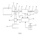
- Fig. 1 depicts an arrangement, according to the present invention, for a drive unit of a vehicle.
- the drive unit incorporates an engine 1 and a mechanical stepped gearbox 2.
- a connecting device is designed to transmit rotary motion from the engine 1 to the stepped gearbox 2.
- the connecting device incorporates an output shaft 3 from the engine 1, a clutch 4 and an input shaft 5 to the gearbox 2.
- the connecting device is designed to constitute during gear changing a rigid rotating unit.
- driving power supplied is led from the gearbox output shaft 6, e.g. via a propeller shaft 7, to the vehicle's driving wheels 8.
- the present invention makes it possible to execute gear changing in the gearbox 2 without using the clutch 4.
- the clutch 4 thus has no function in the present invention but is included in Fig.1, since heavy-duty vehicles do in any case usually need a clutch function at the time of starting and stopping the vehicle.
- the clutch takes the form of a disc clutch of the kind which is conventional for vehicles and which is normally operated by the driver via a clutch pedal.
- An electric rotor machine 9 is arranged on the output shaft 3 of the engine 1.
- the electric rotor machine 9 incorporates a stator 10 and a rotor 11 which is arranged firmly on the output shaft 3 of the engine 1.
- This rotor machine 9 is designed to act upon the output shaft 3 of the engine 1 so that substantially no torque is transmitted during the disengagement and engagement of gears in the gearbox 2.
- a control unit 12 is designed to control the electric rotor machine 9.
- the vehicle incorporates a gearchange control 13 designed to be easily movable sideways when in a position for manual gearchanging, whereby movement to the left causes changing down and movement to the right causes changing up.
- the rotor machine 9 is connected to an electrical energy storage device 14 designed to deliver electrical energy to the rotor machine 9 when the latter functions as a motor and to receive electrical energy from the rotor machine 9 when the latter functions as a generator.
- a control device 15 is arranged to control said energy flow.
- the control unit 12 is designed to control the control device 15 in order to achieve control as desired of the rotor machine 9.
- the gearchange control 13 When a driver of the vehicle wishes to engage a higher or lower gear in the gearbox 2, the gearchange control 13 is moved in the desired direction, and a signal is sent to the control unit 12.
- the control unit 12 which may incorporate a microcomputer, is designed to receive a signal 16 concerning the speed of the engine 1.
- the control unit 12 is also designed to receive a signal 17 concerning the speed of the output shaft 6 of the gearbox 2.
- a possible alternative to this is detecting the speed of the vehicle's propeller shaft 7 or driving wheels 8. It is also possible for the vehicle's speed to be used in order to achieve an engine speed which is in proportion to the speed of the output shaft 6 of the gearbox 2.
- the control unit 12 is designed, before the disengagement of a gear in the gearbox 2, to calculate the torque which the electric rotor machine has to provide to the output shaft 3 of the engine 1 so that the gearwheels enmeshed in the gearbox 2 will not be subject to any torque. Knowledge of the characteristics of the engine 1 and the speed at the time of the engine 1 makes it possible to calculate this torque.
- the control unit 12 thus sends a signal 18 to the control device 15 which is designed to control the energy flow between the electric rotor machine 9 and the energy storage device 14.
- the control device 15 then controls the electric rotor machine 9 so that the latter delivers said calculated torque to the output shaft 3 of the engine 1.
- the gear concerned can be disengaged.
- the control unit 12 then sends a signal 19 to the gearbox 2, whereupon the gear concerned can be disengaged in the gearbox 2.
- Disengagement of gears in the gearbox can be brought about by suitable servo devices. If positive torque is transmitted to the gearbox before the disengagement of a gear in the gearbox, the electric rotor machine 9 functions as a generator and retards the shaft 3. This will result in electrical energy being supplied to the energy storage device 14. If on the contrary negative torque is transmitted to the gearbox 2 before the disengagement of a gear in the gearbox, the electric rotor machine 9 is designed to function as a motor and supply torque to the shaft 3. The energy supplied is drawn from the energy storage device 14.
- the control unit 12 calculates the speed which the shaft 3 must have at the time of engagement of a gear in order to bring about a synchronous speed between the relevant gearwheels which are intended to mesh with one another in the gearbox 2. This speed is calculated by the control unit 12 on the basis of knowledge of the value of the signal 17 concerning the speed of the output shaft 6 of the gearbox 2 and which gear is intended to be engaged.
- the control unit 12 then sends a signal 18 to the control device 15 which controls the energy supply to the electric rotor machine 9.
- the control device 15 controls the energy flow to the rotor machine so that the latter functions as a generator and retards the output shaft 3 of the engine 1 to the calculated speed.
- the control device 15 adjusts the energy flow to the rotor machine 9 so that the latter functions as a motor and accelerates the output shaft 3 of the engine 1 to the calculated speed.
- the shaft 3 reaches said calculated speed, which may be indicated to the control unit 12 by the signal 16, the control unit 12 sends a signal 19 to the gearbox 2, whereupon the gear concerned is engaged.
- an electric rotor machine 9 makes it possible for the aforesaid gearchange process to take place very quickly. It is also possible to control the electric rotor machine 9 very precisely in order to influence the torque and speed of the shaft 3. Moreover, the electric rotor machine 9 generates no noise which could be regarded as disturbing. Another advantage is that no problem arises when changing gear even at very low vehicle speeds, since the electric rotor machine 9 can provide extra torque at speeds below normal idling speed.
- the invention is in no way limited to the embodiments described but may be varied freely within the scope of the patent claims.
- the present electric rotor machine may be combined with currently used methods for engine torque control during gear changes, i.e. by controlling the amount of fuel injected or using an exhaust brake.
- the present electric rotor machine 9 may then be used for finely adjusting the torque and speed to the gearbox 2.
Landscapes
- Engineering & Computer Science (AREA)
- Chemical & Material Sciences (AREA)
- Combustion & Propulsion (AREA)
- Transportation (AREA)
- Mechanical Engineering (AREA)
- Automation & Control Theory (AREA)
- Electric Propulsion And Braking For Vehicles (AREA)
- Hybrid Electric Vehicles (AREA)
- Arrangement Of Transmissions (AREA)
- Control Of Transmission Device (AREA)
Abstract
Description
- The present invention relates to an arrangement and a method for a drive unit of a vehicle according respectively to the preamble to
patent claim 1 and the preamble topatent claim 11. - In motor vehicles it is desirable to be able to change gear in a stepped gearbox without having to use the vehicle's clutch. This has been achieved, according to known technology, by the engine being controlled so that substantially no torque is transmitted from the engine to the gearbox during a gear change, i.e. while disengaging from one gear and engaging another.
- Methods are known from SE 504 717 and SE 502 807 for controlling the torque delivered by an engine to a level such that substantially no torque is transmitted to the gearbox during gear disengagement. Such control of engine torque and speed can be achieved by adjusting the fuel supply to the engine.
- A known practice from SE 502 154 is for gear engagement when changing up to be preceded by using an exhaust brake to reduce the engine speed to such a level that a synchronous speed is reached between the gearwheels which are intended to mesh with one another in the gearbox.
- Controlling an engine by adjusting the amount of fuel supplied is complicated in that the fuel quantity injected is usually controlled by other conditions, some of which are intended to minimise fuel consumption. Nor is using an exhaust brake to reduce engine speed quickly an ideal practice, since it generates noise which may be disturbing.
- Arranging an electric rotor machine on an output shaft of an engine is known in other contexts. These include the use of such a rotor machine as a starter motor for quickly getting the ordinary engine running. It may also be used for damping engine vibration, particularly at low engine speeds, and for providing extra power during vehicle acceleration.
- EP,A2, 348622 describes a stepped speed gearbox for a motor vehicle according to the preamble of
claim 1 and having a synchronising device which comprises an energy transmission system formed as an electrical machine. The machine is used both to retard and to accelerate the gearbox axles during gear changes while the transmission is disconnected from a drive unit. The machine is connected to an energy storage device which enable energy storage or release to the machine during synchronisation. - The object of the present invention is to make gear changing in a mechanical stepped gearbox possible, without using the vehicle's clutch, by controlling more quickly, more precisely and more quietly than by using the known technology mentioned in the introduction the torque and speed delivered to the gearbox during gear changing.
- This object is achieved by the arrangement mentioned in the introduction which is characterised in that said means incorporates an electric rotor machine connected to the connecting device. With such an electric rotor machine it is possible quickly, quietly and precisely to adjust the torque delivered by the engine and its speed via the connecting device so that substantially no torque is transmitted to the gearbox during a gear change.
- According to a preferred embodiment of the invention, said means incorporates a control unit designed to control the electric rotor machine. Such a control unit may be designed to use knowledge of necessary information concerning the state of the vehicle at the time to control a control device so that the rotor machine is loaded with a relevant electric voltage with a view to correcting the torque and speed of said connecting device to a desired level. This may entail the control unit being connected to a device designed to detect the engine speed. Such a device may for example be a sensor which detects the speed of a flywheel on the engine's output shaft.
- The control unit may also be connected to a device designed to detect a parameter related to the speed of an output shaft of the gearbox. Such a device may be a sensor which detects, for example, the speed of the output shaft of the gearbox, the speed of the vehicle's propeller shaft or the speed of the driving wheels.
- According to a preferred embodiment of the invention, the control unit is designed so that, before the disengagement of a gear in the gearbox, the control unit controls the electric rotor machine so that the latter corrects the torque delivered by the engine to such a level that substantially no torque is transmitted to the gearbox. This means that when a positive driving torque is transmitted via the gearwheels enmeshed at the time the control unit will provide the electric rotor machine with a corresponding amount of negative retarding torque.
- If instead a negative torque prevails in the gearwheels enmeshed at the time, which may occur when the vehicle is travelling downhill, the electric rotor machine will provide a corresponding positive driving torque. The gearwheels concerned will therefore not be subject to any torque when the gear concerned is disengaged.
- According to another preferred embodiment of the invention, the control unit is designed so that, before the engagement of a gear in the gearbox, the control unit controls the electric rotor machine so that the connecting device is brought to a speed which is in proportion to the speed of an output shaft of the gearbox, this proportion being determined by the gear concerned. The control unit may in this case use knowledge of the speed of, for example, an output shaft of the gearbox and the gear concerned to calculate the speed at which the connecting device must be when the gear concerned is engaged. This will result, when changing up, in the electric rotor machine retarding the speed of the connecting device to the calculated level, and, when changing up, in its accelerating the connecting device to the calculated speed. This means that the relevant gearwheels in the gearbox which are intended to mesh will have a synchronous speed at which the gear concerned can be engaged.
- According to another preferred embodiment, the electric rotor machine includes a stator and a rotor, and the rotor is arranged in the connecting device. This means that the electric rotor machine can directly transmit a torque or adjust the speed of the connecting device. By way of alternative, the rotor machine may be connected via a transmission element to the connecting device, thereby making it possible to achieve a gear change between them.
- According to another preferred embodiment of the invention, the electric rotor machine is designed to function when necessary as a motor and provide torque to the connecting device and to function when necessary as a generator and retard the connecting device.
- Such a rotor machine does not necessarily have only to act upon the connecting device during a gear change. A rotor machine which functions both as motor and generator may be connected to an electrical energy storage device which delivers electrical energy to the rotor machine when it functions as a motor and receives electrical energy from the rotor machine when it functions as a generator. The energy extracted by reducing the speed of the connecting device may therefore be stored in the energy storage device. This energy may subsequently be used when the connecting device has to be provided with torque and speed. Said electrical energy storage device may include one or more electric batteries or, in the case of short-duration energy storage, take the form of one or more capacitors.
- The present invention also includes a method of a drive unit according to the arrangement described above. On the basis of a known practice of arranging an electric rotor machine on an engine output shaft in a vehicle, the method is characterised in that the electric rotor machine is controlled so that substantially no torque is transmitted from the connecting device to the gearbox during gear changing. Very precise control of the torque and speed of the electric rotor machine is thus possible, unlike the situation according to the known technology whereby the electric rotor machine is substantially used for supplying energy to the ordinary engine and storing braking energy. The electric rotor machine is preferably controlled, before the disengagement of a gear in the gearbox, so as to correct the torque delivered from the engine to such a level that substantially no torque is transmitted to the gearbox. It is also advantageous if the electric rotor machine, before the engagement of a gear in the gearbox, is controlled so that the connecting device is brought to a speed which is in proportion to the speed of an output shaft of the gearbox, this proportion being determined by the gear concerned. Using the electric rotor machine in the foregoing manner makes it possible quickly and with great precision to adjust the torque and speed of the engine so that the disengagement and engagement of the relevant gears can take place without being affected by torque in the gearwheels enmeshed at the time in the gearbox.
- A preferred embodiment of the invention is described below by way of example with reference to the attached drawing, which is as follows:
- Fig. 1
- depicts schematically an arrangement, according to the present invention, for a drive unit of a vehicle.
- Fig. 1 depicts an arrangement, according to the present invention, for a drive unit of a vehicle. The drive unit incorporates an
engine 1 and a mechanicalstepped gearbox 2. A connecting device is designed to transmit rotary motion from theengine 1 to thestepped gearbox 2. The connecting device incorporates anoutput shaft 3 from theengine 1, a clutch 4 and aninput shaft 5 to thegearbox 2. The connecting device is designed to constitute during gear changing a rigid rotating unit. After thegearbox 2, driving power supplied is led from thegearbox output shaft 6, e.g. via apropeller shaft 7, to the vehicle's driving wheels 8. The present invention makes it possible to execute gear changing in thegearbox 2 without using the clutch 4. The clutch 4 thus has no function in the present invention but is included in Fig.1, since heavy-duty vehicles do in any case usually need a clutch function at the time of starting and stopping the vehicle. The clutch takes the form of a disc clutch of the kind which is conventional for vehicles and which is normally operated by the driver via a clutch pedal. - An
electric rotor machine 9 is arranged on theoutput shaft 3 of theengine 1. Theelectric rotor machine 9 incorporates astator 10 and arotor 11 which is arranged firmly on theoutput shaft 3 of theengine 1. Thisrotor machine 9 is designed to act upon theoutput shaft 3 of theengine 1 so that substantially no torque is transmitted during the disengagement and engagement of gears in thegearbox 2. Acontrol unit 12 is designed to control theelectric rotor machine 9. The vehicle incorporates agearchange control 13 designed to be easily movable sideways when in a position for manual gearchanging, whereby movement to the left causes changing down and movement to the right causes changing up. Therotor machine 9 is connected to an electricalenergy storage device 14 designed to deliver electrical energy to therotor machine 9 when the latter functions as a motor and to receive electrical energy from therotor machine 9 when the latter functions as a generator. Acontrol device 15 is arranged to control said energy flow. Thecontrol unit 12 is designed to control thecontrol device 15 in order to achieve control as desired of therotor machine 9. - When a driver of the vehicle wishes to engage a higher or lower gear in the
gearbox 2, thegearchange control 13 is moved in the desired direction, and a signal is sent to thecontrol unit 12. Thecontrol unit 12, which may incorporate a microcomputer, is designed to receive asignal 16 concerning the speed of theengine 1. Thecontrol unit 12 is also designed to receive asignal 17 concerning the speed of theoutput shaft 6 of thegearbox 2. A possible alternative to this is detecting the speed of the vehicle'spropeller shaft 7 or driving wheels 8. It is also possible for the vehicle's speed to be used in order to achieve an engine speed which is in proportion to the speed of theoutput shaft 6 of thegearbox 2. Thecontrol unit 12 is designed, before the disengagement of a gear in thegearbox 2, to calculate the torque which the electric rotor machine has to provide to theoutput shaft 3 of theengine 1 so that the gearwheels enmeshed in thegearbox 2 will not be subject to any torque. Knowledge of the characteristics of theengine 1 and the speed at the time of theengine 1 makes it possible to calculate this torque. Thecontrol unit 12 thus sends asignal 18 to thecontrol device 15 which is designed to control the energy flow between theelectric rotor machine 9 and theenergy storage device 14. Thecontrol device 15 then controls theelectric rotor machine 9 so that the latter delivers said calculated torque to theoutput shaft 3 of theengine 1. As this means that no torque is transmitted between the gearwheels enmeshed at the time in thegearbox 2, the gear concerned can be disengaged. Thecontrol unit 12 then sends asignal 19 to thegearbox 2, whereupon the gear concerned can be disengaged in thegearbox 2. Disengagement of gears in the gearbox can be brought about by suitable servo devices. If positive torque is transmitted to the gearbox before the disengagement of a gear in the gearbox, theelectric rotor machine 9 functions as a generator and retards theshaft 3. This will result in electrical energy being supplied to theenergy storage device 14. If on the contrary negative torque is transmitted to thegearbox 2 before the disengagement of a gear in the gearbox, theelectric rotor machine 9 is designed to function as a motor and supply torque to theshaft 3. The energy supplied is drawn from theenergy storage device 14. - After the disengagement described above of the gear concerned in the gearbox, the
control unit 12 calculates the speed which theshaft 3 must have at the time of engagement of a gear in order to bring about a synchronous speed between the relevant gearwheels which are intended to mesh with one another in thegearbox 2. This speed is calculated by thecontrol unit 12 on the basis of knowledge of the value of thesignal 17 concerning the speed of theoutput shaft 6 of thegearbox 2 and which gear is intended to be engaged. Thecontrol unit 12 then sends asignal 18 to thecontrol device 15 which controls the energy supply to theelectric rotor machine 9. During upward gear changing, thecontrol device 15 controls the energy flow to the rotor machine so that the latter functions as a generator and retards theoutput shaft 3 of theengine 1 to the calculated speed. During downward gear changing, thecontrol device 15 adjusts the energy flow to therotor machine 9 so that the latter functions as a motor and accelerates theoutput shaft 3 of theengine 1 to the calculated speed. When theshaft 3 reaches said calculated speed, which may be indicated to thecontrol unit 12 by thesignal 16, thecontrol unit 12 sends asignal 19 to thegearbox 2, whereupon the gear concerned is engaged. - Using an
electric rotor machine 9 makes it possible for the aforesaid gearchange process to take place very quickly. It is also possible to control theelectric rotor machine 9 very precisely in order to influence the torque and speed of theshaft 3. Moreover, theelectric rotor machine 9 generates no noise which could be regarded as disturbing. Another advantage is that no problem arises when changing gear even at very low vehicle speeds, since theelectric rotor machine 9 can provide extra torque at speeds below normal idling speed. - The invention is in no way limited to the embodiments described but may be varied freely within the scope of the patent claims. For example, it is possible for the present electric rotor machine to be combined with currently used methods for engine torque control during gear changes, i.e. by controlling the amount of fuel injected or using an exhaust brake. The present
electric rotor machine 9 may then be used for finely adjusting the torque and speed to thegearbox 2.
Claims (10)
- Arrangement for a drive unit of a vehicle whereby the drive unit incorporates an engine (1), a mechanical stepped gearbox (2) and a connecting device which is designed to transmit rotary motion from the engine (1) to the stepped gearbox (2), and whereby the arrangement incorporates means designed to act upon the connecting device in such a way that substantially no torque is transmitted from the engine (1) to the gearbox (2) during gear changing, an electric rotor machine (9) which is connected to the connecting device[.],
a control unit (12) which is designed to control the electric rotor machine (9)[.]
characterised in that the control unit (12) is designed, before the disengagement of a gear in the gearbox (2), to control the electric rotor machine (9) so that the latter corrects the torque delivered from the engine (1) to such a level that substantially no torque is transmitted to the gearbox (2). - Arrangement according to claim 1, characterised in that the control unit (12) is designed, before the engagement of a gear in the gearbox (2), to control the electric rotor machine (9) so that the connecting device is brought to a speed which is in proportion to the speed of an output shaft (6) of the gearbox (2), this proportion being determined by the gear concerned.
- Arrangement according to any one of claims 1-2, characterised in that the control unit (12) is connected to a device which is designed to detect the speed of the engine.
- Arrangement according to any one of claims 1-3, characterised in that said control unit (12) is connected to a device which is designed to detect a parameter which is related to the speed of an output shaft (6) in the gearbox (2).
- Arrangement according to any one of the foregoing claims, characterised in that the electric rotor machine (9) incorporates a stator (10) and a rotor (11), and the rotor (11) is arranged on the connecting device.
- Arrangement according to any one of the foregoing claims, characterised in that the electric rotor machine (9) is designed so that, when necessary, it functions as a motor and supplies torque to the connecting device.
- Arrangement according to any one of the foregoing claims, characterised in that said rotor machine (9) is designed so that, when necessary, it functions as a generator and reduces the rotation speed of the connecting device.
- Arrangement according to claim 6 or 7, characterised in that the rotor machine (9) is connected to an electrical energy storage device (14) which delivers electrical energy to the rotor machine (9) when the latter functions as a motor, and receives electrical energy from the rotor machine (9) when the latter functions as a generator.
- Method for a drive unit of a vehicle whereby the drive unit incorporates an engine (1), a mechanical stepped gearbox (2) and a connecting device which is designed to transmit rotary motion from the engine (1) to the stepped gearbox (2), and an electric rotor machine (9) is connected to the connecting device, wherin the electric rotor machine (9) is controlled in such a way that substantially no torque is transmitted from the connecting device to the gearbox (2) during gear changing [.]
characterised in that before the disengagement of a gear in the gearbox (2) the electric rotor machine (9) is controlled so as to correct the torque delivered from the engine (1) to such a level that substantially no torque is transmitted to the gearbox (2). - Method according to claim 9, characterised in that before the disengagement of a gear in the gearbox (2) the electric rotor machine (9) is controlled so that the connecting device is brought to a speed which is in proportion to the speed of an output shaft (6) of the gearbox, this proportion being determined by the gear concerned.
Applications Claiming Priority (3)
| Application Number | Priority Date | Filing Date | Title |
|---|---|---|---|
| SE9802411A SE510654C2 (en) | 1998-07-06 | 1998-07-06 | Device and method of a drive unit of a vehicle |
| SE9802411 | 1998-07-06 | ||
| PCT/SE1999/001162 WO2000003163A1 (en) | 1998-07-06 | 1999-06-29 | Arrangement and method for a driving unit in a vehicle |
Publications (2)
| Publication Number | Publication Date |
|---|---|
| EP1093552A1 EP1093552A1 (en) | 2001-04-25 |
| EP1093552B1 true EP1093552B1 (en) | 2003-08-27 |
Family
ID=20411970
Family Applications (1)
| Application Number | Title | Priority Date | Filing Date |
|---|---|---|---|
| EP99933400A Expired - Lifetime EP1093552B1 (en) | 1998-07-06 | 1999-06-29 | Arrangement and method for a driving unit in a vehicle |
Country Status (7)
| Country | Link |
|---|---|
| US (1) | US6505109B1 (en) |
| EP (1) | EP1093552B1 (en) |
| JP (1) | JP2002520990A (en) |
| BR (1) | BR9911831A (en) |
| DE (1) | DE69910785T2 (en) |
| SE (1) | SE510654C2 (en) |
| WO (1) | WO2000003163A1 (en) |
Families Citing this family (23)
| Publication number | Priority date | Publication date | Assignee | Title |
|---|---|---|---|---|
| SE516751C2 (en) | 2000-05-30 | 2002-02-26 | Volvo Lastvagnar Ab | Gearbox for motor vehicles |
| SE516707C2 (en) * | 2000-05-30 | 2002-02-19 | Volvo Lastvagnar Ab | Power units for motor vehicles |
| EP1167834A1 (en) * | 2000-06-29 | 2002-01-02 | BorgWarner Inc. | Power transmission system having an electromagnetic device for improved ratio changing events |
| SE516313C2 (en) * | 2000-09-07 | 2001-12-17 | Volvo Personvagnar Ab | Method and apparatus for controlling a drive system |
| DE50103908D1 (en) * | 2001-12-12 | 2004-11-04 | Siemens Ag | Drive device for a motor vehicle with an internal combustion engine, a starter generator and a manual transmission |
| SE521538C2 (en) * | 2002-03-19 | 2003-11-11 | Scania Cv Ab | Arrangement and procedure for permitting disassembly of a gear in a gearbox |
| GB2386932A (en) * | 2002-03-28 | 2003-10-01 | Luk Lamellen & Kupplungsbau | Method of controlling engine torque during a gear shift |
| CN100362265C (en) * | 2004-12-30 | 2008-01-16 | 财团法人工业技术研究院 | Gear shifting control method of gear type gearbox of composite power vehicle |
| FR2887496B1 (en) * | 2005-06-27 | 2007-09-14 | Peugeot Citroen Automobiles Sa | METHOD FOR PILOTING THE COUPLING OR DECOUPLING OF TWO ENGINES OF A PARALLEL HYBRID MOTOR POWERTRAIN |
| DE102006003715A1 (en) * | 2006-01-26 | 2007-08-02 | Zf Friedrichshafen Ag | Synchronizing automated gearbox with matching to input revolution rate involves controlling additional electrical machine, optionally main drive motor, so input revolution rate to be adjusted with drive gear engaged has desired time profile |
| DE102007002343A1 (en) * | 2007-01-16 | 2008-07-17 | Zf Friedrichshafen Ag | Method for dynamically determining a clutch resting point |
| DE102007037530A1 (en) * | 2007-08-09 | 2009-02-12 | Zf Friedrichshafen Ag | Transmission for a vehicle comprises a gearing element interacting with a further gearing element via switching elements and/or decoupled from a torque-guiding region via one switching element |
| DE102007038772A1 (en) * | 2007-08-16 | 2009-02-19 | Zf Friedrichshafen Ag | A method for performing a circuit in hybrid operation in a parallel hybrid vehicle |
| DE102007038771B4 (en) | 2007-08-16 | 2025-03-20 | Zf Friedrichshafen Ag | Method for starting the internal combustion engine during a power shift in parallel hybrid vehicles |
| DE102007038775A1 (en) | 2007-08-16 | 2009-02-19 | Zf Friedrichshafen Ag | Method for carrying out a load circuit in vehicles with electric drive |
| DE102007038773A1 (en) * | 2007-08-16 | 2009-03-12 | Zf Friedrichshafen Ag | Method for carrying out a traction-interrupted circuit in a parallel hybrid vehicle |
| DE102007038774A1 (en) * | 2007-08-16 | 2009-02-19 | Zf Friedrichshafen Ag | Method for carrying out a load circuit in parallel hybrid vehicles in hybrid operation |
| DE102007041569A1 (en) | 2007-09-01 | 2009-03-05 | Zf Friedrichshafen Ag | Method for controlling and / or regulating a hybrid drive arrangement |
| US9028362B2 (en) | 2011-02-01 | 2015-05-12 | Jing He | Powertrain and method for a kinetic hybrid vehicle |
| DE102011112753B4 (en) * | 2011-08-25 | 2015-12-31 | Ide Tec GmbH | Hybrid powertrain and method of operating the same |
| SE1250702A1 (en) * | 2012-06-27 | 2013-12-28 | Scania Cv Ab | Procedure for changing the gear of a vehicle |
| DE102015003900A1 (en) * | 2015-03-26 | 2016-11-17 | Man Truck & Bus Ag | Method for performing a gear shift in parallel hybrid vehicles |
| DE102016218115A1 (en) | 2016-09-21 | 2018-03-22 | Voith Patent Gmbh | Method for switching a claw switching element |
Citations (1)
| Publication number | Priority date | Publication date | Assignee | Title |
|---|---|---|---|---|
| EP0348622A2 (en) * | 1988-04-29 | 1990-01-03 | Volkswagen Aktiengesellschaft | Stepped shift transmission |
Family Cites Families (10)
| Publication number | Priority date | Publication date | Assignee | Title |
|---|---|---|---|---|
| GB8716973D0 (en) * | 1987-07-17 | 1987-08-26 | Automotive Prod Plc | Transmission |
| GB8810365D0 (en) * | 1988-04-30 | 1988-06-08 | Automotive Prod Plc | Power line to drive vehicle |
| US5148899A (en) * | 1991-11-22 | 1992-09-22 | Ford Motor Company | Method and apparatus for locking out the clutch of a manual transmission |
| SE502807C2 (en) | 1994-05-13 | 1996-01-22 | Scania Cv Ab | Procedure for controlling the engine torque during shifting |
| DE4434111A1 (en) * | 1994-09-23 | 1996-03-28 | Kongsberg Automotive Technolog | Control for an automatically operated clutch |
| US6148784A (en) * | 1995-08-31 | 2000-11-21 | Isad Electronic Systems Gmbh & Co. Kg | Drive systems, especially for a motor vehicle, and method of operating same |
| JP3456329B2 (en) | 1995-12-08 | 2003-10-14 | アイシン・エィ・ダブリュ株式会社 | Control device for vehicle drive unit |
| SE504717C2 (en) | 1996-02-07 | 1997-04-14 | Scania Cv Ab | Procedure for correction of the engine torque during shifting |
| DE19615742C1 (en) * | 1996-04-20 | 1997-05-07 | Daimler Benz Ag | Motor vehicle drive train with electric machine providing compensatory torque during gear changes |
| DE19837115B4 (en) * | 1998-08-17 | 2009-04-02 | Zf Sachs Ag | Drive arrangement for a motor vehicle |
-
1998
- 1998-07-06 SE SE9802411A patent/SE510654C2/en not_active IP Right Cessation
-
1999
- 1999-06-29 DE DE69910785T patent/DE69910785T2/en not_active Expired - Fee Related
- 1999-06-29 US US09/720,948 patent/US6505109B1/en not_active Expired - Fee Related
- 1999-06-29 EP EP99933400A patent/EP1093552B1/en not_active Expired - Lifetime
- 1999-06-29 WO PCT/SE1999/001162 patent/WO2000003163A1/en not_active Ceased
- 1999-06-29 JP JP2000559363A patent/JP2002520990A/en active Pending
- 1999-06-29 BR BR9911831-9A patent/BR9911831A/en active Search and Examination
Patent Citations (1)
| Publication number | Priority date | Publication date | Assignee | Title |
|---|---|---|---|---|
| EP0348622A2 (en) * | 1988-04-29 | 1990-01-03 | Volkswagen Aktiengesellschaft | Stepped shift transmission |
Also Published As
| Publication number | Publication date |
|---|---|
| EP1093552A1 (en) | 2001-04-25 |
| SE9802411L (en) | 1999-06-14 |
| BR9911831A (en) | 2001-05-29 |
| WO2000003163A1 (en) | 2000-01-20 |
| SE510654C2 (en) | 1999-06-14 |
| DE69910785D1 (en) | 2003-10-02 |
| US6505109B1 (en) | 2003-01-07 |
| SE9802411D0 (en) | 1998-07-06 |
| JP2002520990A (en) | 2002-07-09 |
| DE69910785T2 (en) | 2004-07-08 |
Similar Documents
| Publication | Publication Date | Title |
|---|---|---|
| US6505109B1 (en) | Arrangement and method for a driving unit in a vehicle | |
| US5595551A (en) | Method for control of engine torque during gear changing | |
| US7498757B2 (en) | Control device for a hybrid electric vehicle | |
| US6299563B1 (en) | Control system for hybrid vehicle | |
| US6569055B2 (en) | Four-wheel drive hybrid vehicle | |
| US7477031B2 (en) | Control device for hybrid electric vehicle | |
| EP1177930B1 (en) | A method and a system for controlling the propulsion of a motor vehicle | |
| US6712165B1 (en) | Hybrid vehicle | |
| JP3415123B2 (en) | Apparatus and method for active transmission synchronization and shifting | |
| CN1275790C (en) | Power driving system | |
| US7228926B2 (en) | Apparatus for controlling hybrid vehicle | |
| US20020039950A1 (en) | Drive train for a motor vehicle | |
| US20080070745A1 (en) | Gear shift control device for a hybrid electric vehicle | |
| US20070219045A1 (en) | Control device for a hybrid electric vehicle | |
| CN101134436A (en) | Hybrid Vehicle Controls | |
| JP2005130564A (en) | Control device for hybrid vehicle | |
| JP2007223421A (en) | Control device for hybrid electric vehicle | |
| EP3071464A1 (en) | Method for controlling gear shifting in a hybrid driveline by use of an electric machine | |
| EP1547848B1 (en) | Apparatus for controlling a gear ratio changing operation in a transmission | |
| KR20040030430A (en) | Hybrid vehicle system | |
| US20190299975A1 (en) | Method and system for starting an internal combustion engine of a hybrid vehicle | |
| US20150210262A1 (en) | Method and apparatus for controlling a torque converter clutch in a multi-mode powertrain system | |
| US7367917B2 (en) | Shift change control system and automatic transmission system of automobile | |
| JP2000115912A (en) | Hybrid vehicle control device | |
| EP0403127B1 (en) | Automatic gear change control apparatus for automobile and method of controlling same |
Legal Events
| Date | Code | Title | Description |
|---|---|---|---|
| PUAI | Public reference made under article 153(3) epc to a published international application that has entered the european phase |
Free format text: ORIGINAL CODE: 0009012 |
|
| 17P | Request for examination filed |
Effective date: 20010206 |
|
| AK | Designated contracting states |
Kind code of ref document: A1 Designated state(s): DE FR GB IT |
|
| 17Q | First examination report despatched |
Effective date: 20020702 |
|
| GRAH | Despatch of communication of intention to grant a patent |
Free format text: ORIGINAL CODE: EPIDOS IGRA |
|
| GRAH | Despatch of communication of intention to grant a patent |
Free format text: ORIGINAL CODE: EPIDOS IGRA |
|
| GRAA | (expected) grant |
Free format text: ORIGINAL CODE: 0009210 |
|
| AK | Designated contracting states |
Designated state(s): DE FR GB IT |
|
| PG25 | Lapsed in a contracting state [announced via postgrant information from national office to epo] |
Ref country code: IT Free format text: LAPSE BECAUSE OF FAILURE TO SUBMIT A TRANSLATION OF THE DESCRIPTION OR TO PAY THE FEE WITHIN THE PRESCRIBED TIME-LIMIT;WARNING: LAPSES OF ITALIAN PATENTS WITH EFFECTIVE DATE BEFORE 2007 MAY HAVE OCCURRED AT ANY TIME BEFORE 2007. THE CORRECT EFFECTIVE DATE MAY BE DIFFERENT FROM THE ONE RECORDED. Effective date: 20030827 Ref country code: FR Free format text: LAPSE BECAUSE OF FAILURE TO SUBMIT A TRANSLATION OF THE DESCRIPTION OR TO PAY THE FEE WITHIN THE PRESCRIBED TIME-LIMIT Effective date: 20030827 |
|
| REG | Reference to a national code |
Ref country code: GB Ref legal event code: FG4D |
|
| REF | Corresponds to: |
Ref document number: 69910785 Country of ref document: DE Date of ref document: 20031002 Kind code of ref document: P |
|
| PG25 | Lapsed in a contracting state [announced via postgrant information from national office to epo] |
Ref country code: GB Free format text: LAPSE BECAUSE OF NON-PAYMENT OF DUE FEES Effective date: 20040629 |
|
| PLBE | No opposition filed within time limit |
Free format text: ORIGINAL CODE: 0009261 |
|
| STAA | Information on the status of an ep patent application or granted ep patent |
Free format text: STATUS: NO OPPOSITION FILED WITHIN TIME LIMIT |
|
| 26N | No opposition filed |
Effective date: 20040528 |
|
| EN | Fr: translation not filed | ||
| GBPC | Gb: european patent ceased through non-payment of renewal fee |
Effective date: 20040629 |
|
| PGFP | Annual fee paid to national office [announced via postgrant information from national office to epo] |
Ref country code: DE Payment date: 20060622 Year of fee payment: 8 |
|
| PG25 | Lapsed in a contracting state [announced via postgrant information from national office to epo] |
Ref country code: DE Free format text: LAPSE BECAUSE OF NON-PAYMENT OF DUE FEES Effective date: 20080101 |