EP1093117A2 - Contact magnetic head supporting structure - Google Patents
Contact magnetic head supporting structure Download PDFInfo
- Publication number
- EP1093117A2 EP1093117A2 EP00101001A EP00101001A EP1093117A2 EP 1093117 A2 EP1093117 A2 EP 1093117A2 EP 00101001 A EP00101001 A EP 00101001A EP 00101001 A EP00101001 A EP 00101001A EP 1093117 A2 EP1093117 A2 EP 1093117A2
- Authority
- EP
- European Patent Office
- Prior art keywords
- contact
- magnetic head
- support
- beams
- magnetic
- Prior art date
- Legal status (The legal status is an assumption and is not a legal conclusion. Google has not performed a legal analysis and makes no representation as to the accuracy of the status listed.)
- Withdrawn
Links
Images








Classifications
-
- G—PHYSICS
- G11—INFORMATION STORAGE
- G11B—INFORMATION STORAGE BASED ON RELATIVE MOVEMENT BETWEEN RECORD CARRIER AND TRANSDUCER
- G11B5/00—Recording by magnetisation or demagnetisation of a record carrier; Reproducing by magnetic means; Record carriers therefor
- G11B5/48—Disposition or mounting of heads or head supports relative to record carriers ; arrangements of heads, e.g. for scanning the record carrier to increase the relative speed
- G11B5/58—Disposition or mounting of heads or head supports relative to record carriers ; arrangements of heads, e.g. for scanning the record carrier to increase the relative speed with provision for moving the head for the purpose of maintaining alignment of the head relative to the record carrier during transducing operation, e.g. to compensate for surface irregularities of the latter or for track following
- G11B5/60—Fluid-dynamic spacing of heads from record-carriers
- G11B5/6005—Specially adapted for spacing from a rotating disc using a fluid cushion
-
- G—PHYSICS
- G11—INFORMATION STORAGE
- G11B—INFORMATION STORAGE BASED ON RELATIVE MOVEMENT BETWEEN RECORD CARRIER AND TRANSDUCER
- G11B21/00—Head arrangements not specific to the method of recording or reproducing
- G11B21/16—Supporting the heads; Supporting the sockets for plug-in heads
- G11B21/24—Head support adjustments
-
- G—PHYSICS
- G11—INFORMATION STORAGE
- G11B—INFORMATION STORAGE BASED ON RELATIVE MOVEMENT BETWEEN RECORD CARRIER AND TRANSDUCER
- G11B5/00—Recording by magnetisation or demagnetisation of a record carrier; Reproducing by magnetic means; Record carriers therefor
- G11B5/48—Disposition or mounting of heads or head supports relative to record carriers ; arrangements of heads, e.g. for scanning the record carrier to increase the relative speed
- G11B5/4806—Disposition or mounting of heads or head supports relative to record carriers ; arrangements of heads, e.g. for scanning the record carrier to increase the relative speed specially adapted for disk drive assemblies, e.g. assembly prior to operation, hard or flexible disk drives
- G11B5/4833—Structure of the arm assembly, e.g. load beams, flexures, parts of the arm adapted for controlling vertical force on the head
Definitions
- the present invention relates to a structure for supporting a contact magnetic head having a contact pad.
- a floppy disk and a hard disk are known as magnetic recording media generally used in a personal computer.
- the floppy disk is an exchangeable magnetic recording medium, and has a feature in that it can be carried easily and it is durable against an impact, though it is inferior in recording density to the hard disk.
- the hard disk is a fixed magnetic recording medium and has a feature in that it is high in recording density and also high in recording/reproducing speed, though it cannot be extracted from a unit and it is weak in an impact.
- recording/reproducing on the floppy disk 10 is performed as follows.
- the cover 12b is slid in the direction of the arrow F so that the window 12a opens.
- An adapter 22 is moved forward/backward in the direction of the arrow G through a tracking mechanism 20 while the magnetic disk 14 is rotated in the direction of the arrow A.
- the magnetic head 24 provided on the tip of the adapter 22 is moved onto a predetermined track.
- Such a tracking system is generally called a transverse system.
- the movable range of the adapter 22 is narrow so that the area of the window 12a can be made small. Therefore, the transverse system is used chiefly as the tracking system for the floppy disk 10.
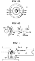
- Fig. 15 shows an example of a hard disk unit.
- a hard disk unit 28 is designed so that a hard disk 30 of an aluminum alloy or the like, a magnetic head 34, and a drive constituted by an actuator 40 and the like are integrated and put into a card case 32 tightly.
- the magnetic head 34 is attached to the tip of an adapter 38 through a bearer 36.
- the base end of the adapter 38 is attached to the actuator 40.
- recording/reproducing on the hard disk 30 is performed as follows.
- the actuator 40 rocks the adapter 38 in the direction of the arrow H while the hard disk 30 is rotated in the direction of the arrow A.
- the magnetic head 34 is moved onto a predetermined track.
- Such a tracking system is generally called an in-line system.
- the magnetic head 34 can be positioned easily.
- the in-line system is suitable for high-density recording/reproducing. Therefore, the in-line system is used chiefly as the tracking system for the hard disk 30.
- the bulk magnetic head 24 generally used for a floppy disk in the background art has the track width in a range of from 50 ⁇ m to 200 ⁇ m. Therefore, there has been a problem that the recording density cannot be made high in comparison with that in the hard disk. Accordingly, if the contact magnetic head 50 having such a structure as shown in Fig. 16 is applied to the floppy disk 10, it can be expected to realize high recording density in the floppy disk.
- the area of the window 12a can be reduced in comparison with the case where the in-line system is used as the tracking system for the floppy disk.
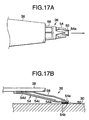
- the size of the window 12a of the floppy disk 10 is standardized as 8 ⁇ 24 mm. Therefore, if the structure for supporting the hard disk 30 is appropriated directly to the floppy disk 10, there is a problem that the contact magnetic head 50 cannot be settled within the window 12a as shown in Fig. 18B.
- a magnetic gap on the tip of the magnetic pole pad runs the position away, by a predetermined distance (hereinafter, this will be referred to as "gap center offset"), from a gap center (a straight line which passes through the rotation center of the magnetic disk 14). Therefore, there is a problem that a skew angle ⁇ is produced on the head tip so as to lower the electromagnetic conversion efficiency in recording/reproducing.
- the support 54 is shortened.
- the Z-height is also standardized. Therefore, in order to appropriate the support structure for the hard disk 30 directly to the floppy disk 10, it is necessary to shorten only the support 54 while keeping the Z-height at a standard value.
- the Z-height since the Z-height has a tolerance range, the Z-height of each assembled magnetic head fluctuates within the tolerance range.
- the support 54 has a certain measure of length, even if the Z-height (Z) is larger than a set value Z o (Fig. 19A) or smaller (Fig. 19B) within the tolerance range, the fluctuations in reaction torque M acting on the contact magnetic head 50 is so small that contact loads on the respective contact pads 52a, 52b and 52b can be kept substantially equal if the position of the head chip 50a relative to the support 54, and the position where the pivot spring 56 applies a load are adjusted.
- a floppy disk has been recently requested not only to make its recording density high but also to make its size small. This is because, if a floppy disk can be miniaturized, wider application of the floppy disk, for example, such as a digital camera, a digital AV, etc. can be expected. To that end, not only is it necessary to make the track width narrower, but also it is necessary to make the lateral width of the window 12a narrower. However, in the support structure shown in Fig. 18B, it is necessary to make the support shorter as the lateral width of the window 12a becomes narrower. There is therefore a problem that this accelerates the load imbalance, so that stable contact running becomes more difficult.
- the invention particularly relates to a structure for supporting a contact magnetic head which is suitable for high-density recording/reproducing on a floppy disk used in a computer, a digital camera, a digital AV, etc.
- the support includes two above-mentioned support beams for supporting the contact magnetic head. Further, the two support beams may be connected by at least one bridge. Particularly, the support beams are preferably connected by the bridge at the vicinities of the tips of the first beams.
- the contact pressure giving means includes an arm portion and a load giving beam provided to have a base end near a tip of the arm portion and extend from the base end in a direction opposite to the arm portion.
- a flexible portion is provided near a base end and/or tip of the arm portion.
- the flexible portion is formed by bending the arm portion sideways.
- the support beam is constituted by a first beam and a second beam which is provided to extend from the vicinity of the tip of the first beam as its base end in the direction opposite to the first beam, so that it becomes easy to dispose a contact pad having a magnetic pole on the gap center. It is therefore possible to make the lowering of the electromagnetic conversion efficiency of the contact magnetic head minimum. In addition, it is possible to shorten the first beam while keeping the gap center offset substantially at zero, so that it is possible to reduce the window width of an exchangeable magnetic recording medium. Thus, contamination on the surface of the magnetic recording medium and deterioration of reliability due to the contamination are further restrained.
- a predetermined pressure force is given by the contact pressure giving means to a contact magnetic head supported by the support beams each constituted by the first and second beams which are provided to extend in the directions opposite to each other, so that the fluctuations in a contact load due to the fluctuations in Z-height is reduced and abrasion of the magnetic pole is restrained.
- the pressure force given by the contact pressure giving means is optimized, self-induced vibration is restrained even if there is a large friction coefficient between the contact pad and the magnetic recording medium.
- Figs. 1A to 1C show a structure for supporting a contact magnetic head according to an embodiment of the present invention.
- a structure for supporting a contact magnetic head according to this embodiment (hereinafter, referred to as "support structure” simply) 60 has a base plate 62, an adapter 64 attached to the lower surface of the base plate 62, and a bearer 66 attached to the lower surface of the adapter 64.
- the bearer 66 is constituted by a pivot spring 68 and a support 70.
- a contact magnetic head 50 is attached to the support 70.
- the base plate 62 is provided so as to be attached to a tracking mechanism 20 (see Fig. 13) for a floppy disk in which a transverse system is adopted. To that end, a threaded hole 62a for fixing the base plate 62 to the tracking mechanism 20 is provided at the base end of the base plate 62, as shown in Figs. 2A and 2B.
- a threaded hole 62a for fixing the base plate 62 to the tracking mechanism 20 is provided at the base end of the base plate 62, as shown in Figs. 2A and 2B.
- four round through holes 62b, 62c, 62d and 62e used for positioning the adapter 64 when the adapter 64 is welded are provided, and an oval through hole 62f also for positioning the adapter 64 is provided substantially at the center of the base plate 62.
- the adapter 64 is used for connecting the base plate 62 with the bearer 66, and shaped like a battledore as shown in Figs. 3A and 3B.
- a round through hole 64a used for positioning the adapter 64 when the base plate 62 and the adapter 64 are welded is provided substantially at the center of the adapter 64.
- a quadrangular wiring window 64b is provided adjacently to the round through hole 64a, and a quadrangular opening portion 64c is provided on the tip side of the adapter 64.
- pivot spring 68 and the support 70 are fixed to side arm portions (hereinafter, these portions will be referred to as "left and right side arm portions” respectively) 64d and 64e located on the left and right of the opening portion 64c when those portions are viewed from the base end of the adapter 64 to the tip of the same, respectively.
- this embodiment has such a configuration that the adapter 64 is fixed to the lower surface of the base plate 62, and the base plate 62 is fixed to the tracking mechanism 20, the adapter 64 may be fixed directly to the tracking mechanism 20.
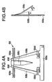
- the pivot spring 68 has a base portion 68a, two arm portions 68b and 68b, and a load giving beam 68c, as shown in Figs. 4A and 4B.
- the base portion 68a is a portion for fixing the pivot spring 68 to the left arm portion 64d of the adapter 64.
- the two arm portions 68b and 68b are provided to extend symmetrically from the vicinities of opposite ends of the base portion 68a toward the center respectively.
- a flexible portion 68d bent inward into a U-shape is provided on the base portion 68a side of each of the arm portions 68b and 68b.
- flexible portions 68e and 68e bent outward into a U-shape are provided on the tips of the two arm portions 68b and 68b respectively.
- These flexible portions 68d and 68e are portions for adjusting a pressure force given to the contact magnetic head by the load giving beam 68c.
- the load giving beam 68c is provided to extend from the vicinities of the tips of the arm portions 68b and 68b toward the opposite direction to the arm portions 68b and 68b.
- the base end of the load giving beam 68c is integrated with the tips of the arm portions 68b and 68b through the flexible portions 68e and 68e.
- the words "opposite direction" includes not only the case where the center line of the arm portions 68b and 68b is perfectly parallel with the center line of the load giving beam 68c but also the case where the former center line crosses the latter center line at an angle of 90° or less.
- the magnitude of the crossing angle between those center lines may be determined desirably in consideration of the shape of the pivot spring 68, the shape of the support 70, the difficulty of the producing process, and the like.
- the load giving beam 68c is bent downward near its base end and substantially at its central portion at predetermined bending angles ⁇ and ⁇ respectively. Further, positioning protrusions 68f and 68f are provided at the base end of the load giving beam 68c.
- An elastic material is used for the pivot spring 68 so that a predetermined pressure force is given to the contact magnetic head.
- a sheet of stainless steel 20 to 25 ⁇ m thick is used.
- the bending angles ⁇ and ⁇ of the load giving beam 68c, the shapes of the flexible portions 68d and 68e and the shape of the arm portion 68b may be determined so that a predetermined pressure force is given substantially to the centroidal position of the contact magnetic head 50 by the load giving beam 68c.
- the pivot spring 68 is thus constituted by the arm portions 68b and 68b, and the load giving beam 68c which are provided to extend in opposite directions to each other, there is an advantage that it is made easy to attach both the pivot spring 68 and the support 70 into a narrow space on the tip of the adapter 64.
- the flexible portions 68d and 68e are provided on the base end sides and on the tip sides, respectively, of the arm portions 68b and 68b, there is an advantage that it is possible to adjust the pressure force of the load giving beam 68c easily.
- the pressure force can be adjusted easily only by changing the length and lateral width of the flexible portions 68d and 68e.
- the support 70 is formed into an L-shape which is constituted by a base portion 72a and a strip portion 72b provided to extend from one side edge of the base portion 72a in the longitudinal direction of the adapter 64 (see, Fig. 8A).
- Two support beams 76a and 76a are provided to extend from the strip portion 72b in the rotational direction of a magnetic disk (not shown).
- a three-layer laminate material constituted by a stiffener layer 72, an insulating layer 74, and a conductor layer 76 is used for the support 70 as shown in Fig. 5B.
- the stiffener layer 72 is formed of stainless steel 20 to 25 ⁇ m thick in order to give rigidity to the support 70.
- the insulating layer 74 is formed of a bonding agent 25 to 50 ⁇ m thick in order to ensure the insulation between the stiffener layer 72 and the conductor layer 76.
- the conductor layer 76 to be an electrode of a contact magnetic head (not shown) is formed of stainless steel 5 to 25 ⁇ m thick.
- the base portion 72a formed of the stiffener layer 72 is provided with two wiring windows 72c and 72c from which the conductor layer 76 located in the lowermost layer of the support 70 is exposed.
- a mounting piece 72e for mounting thereon the base end portion of the load giving beam 68c of the pivot spring 68 is provided substantially at the center of the strip portion 72b so as to project therefrom.
- overhang portions 72d and 72d for mounting thereon the flexible portions 68e and 68e of the pivot spring 68 are provided on opposite ends of the strip portion 72b respectively.
- the two support beams 76a and 76a formed of the conductor layer 76 have the same shapes.
- the support beams 76a and 76a are provided bilaterally symmetrically with respect to a magnetic pole pad (not shown) of the contact magnetic head attached to the tips of the support beams 76a and 76a.
- the support beams 76a and 76a have first beams 76b and 76b and second beams 76c and 76c respectively.
- the first beams 76b and 76b are provided to extend from the strip portion 72b of the stiffener layer 72 as the base ends in the rotational direction of the magnetic disk and in parallel with the magnetic disk.
- the base end side of each of the first beams 76b and 76b has substantially a triangular shape, in which three through holes 76d, ... are provided for adjusting the rigidity of the first beam 76b.
- the first beams 76b and 76b are connected to each other substantially at the centers of the beams 76b and 76b by a first bridge 72f of the stiffener layer 72 through the insulating layer 74.
- overhang pieces 76e and 76e which overhang inward are provided on the tips of the first beams 76b and 76b respectively.
- the tips of the respective overhang pieces 76e and 76e are connected with each other, through the insulating layer 74, by a second bridge 72g of the stiffener layer 72.
- first bridge 72f When the first beams 76b and 76b are thus fixed substantially at their respective centers by the first bridge 72f, there is an advantage that it is possible to restrain lateral self-induced vibration generated when the contact magnetic head follows a servo signal (vibration generated perpendicularly to the rotational direction of the disk), so that the accuracy in positioning the contact magnetic head is improved.
- the tips of the first beams 76b and 76b are fixed by the second bridge 72g, there is an advantage that it is possible to restrain longitudinal self-induced vibration generated when the support beams 76a and 76a are opened/shut in the right and left directions (vibration generated in the rotation direction of the disk).
- first beams 76b and 76b are connected to wiring portions 76h and 76h provided on the lower surface of the base portion 72a of the stiffener layer 72 through the lead wires 76g and 76g formed of the conductor layer 76, respectively.
- the second beams 76c and 76c are provided to extend from the vicinities of the tip ends of the first beams 76b and 76b in the opposite direction to the first beams 76b and 76b and in parallel with the magnetic disk respectively.
- welded pieces 76f and 76f each formed into a substantially L-shape are provided to extend from the tips of the second beams 76c and 76c in parallel with the magnetic disk and in the direction opposite to the second beams 76c and 76c respectively.
- the words "opposite direction” includes not only the case where the center line of the first beams 76b, and the center line of the second beams 76c or the center line of the welded pieces 76f are perfectly parallel with each other, but also the case where those center lines cross each other at an angle of 90° or less. Then, the magnitude of the crossing angle between the center lines may be determined desirably, in consideration of the shape of the support 70, the shape of the pivot spring 68, the difficulty of the producing process, and the like, in the same manner as in the case of the pivot spring 68.
- the welded pieces 76f and 76f are provided, through the insulating layer 74, with a mounting portion 72h formed of the stiffener layer 72.
- the mounting portion 72h is attached so that one side of the mounting portion 72h approaches the vicinities of the tips of the second beams 76c and 76c.
- the mounting portion 72h is designed to be bent downward at the vicinities of the tips of the second beams 76c and 76c when a pressure force is given to the mounting portion 72h by the load giving beam 68c.
- the mounting portion 72h is provided with two wiring windows 72i and 72i from which the tips of the left and right welded pieces 76f and 76f are exposed.
- Figs. 6A to 6C are an enlarged view of the mounting portion 72h and the contact magnetic head 50 attached to the mounting portion 72h.
- the contact magnetic head 50 is an induction type thin-film magnetic head produced by using a lithographic technique.
- a contact pad (magnetic pole pad) 52a having a magnetic pole
- two contact pads (auxiliary pads) 52b and 52b for stabilizing the contact state of the magnetic pole pad 52a.
- a magnetic circuit (not shown) for recording/reproducing magnetic information is formed inside the head chip 50a.
- opposite ends of a coil (not shown) formed around the magnetic circuit are connected to Au pads 50b and 50b formed on the top surface of the head chip 50a.
- the dead weight of the contact magnetic head 50 is very light, that is, about 0.014 ⁇ 10 -3 N, so that the contact magnetic head 50 is supported horizontally by the two support beams 76a and 76a insulated electrically in the no-load state.
- the contact magnetic head 50 is supported substantially stably by the two support beams 76a and 76a so that the contact pads can be brought into uniform contact with the magnetic recording medium.
- the thickness of the head chip 50a of the contact magnetic head 50 used in the present invention is required to be not more than 100 ⁇ m. This is because a measure of flexibility is required of the head chip 50a in order to stabilize contact running. If the thickness of the head chip 50a exceeds 100 ⁇ m, the head chip 50a cannot follow a slight waving of the surface of the magnetic disk generated during contact running, so that it becomes undesirably difficult to bring the three contact pads into contact with the magnetic disk simultaneously.
- the thickness of the head chip 50a is not more than 50 ⁇ m.
- the size and number of the through holes 76d and 76d provided in the first beams 76b and 76b, the lateral width and length of the first beams 76b and 76b and the second beams 76c and 76c, or the like, may be determined so that the spring constants of the support beams 76a and 76a can take predetermined values.
- the adapter 64 is disposed under the base plate 62, and they are put on top of each other so that the center of the round through holes 62b and 64a of the base plate 62 coincides with the center of the round through hole 64a of the adapter 64. Then, the base plate 62 and the adapter 64 are welded.
- the pivot spring 68 produced in advance is disposed under the adapter 64.
- the base portion 68a of the pivot spring 68 and the left arm portion 64d of the adapter 64 are put on each other, and welded with each other.
- Figs. 7A and 7B show the state where the pivot spring 68 and the adapter 64 have been welded.
- the adapter 64 is indicated by the imaginary line (two-dot chain line), and hatching is given to the pivot spring 68, in order to make them easy to see.
- the contact magnetic head 50 produced in advance is disposed under the mounting portion 72h provided on the tips of the second beams 76c and 76c of the support 70 produced likewise in advance.
- the tips of the welded pieces 76f and 76f are put on, and welded with the Au pads 50b and 50b respectively.
- the support 70 mounted with the contact magnetic head 50 is disposed under the adapter 64 mounted with the pivot spring 68.
- the strip portion 72b of the support 70 and the right arm portion 64e of the adapter 64 are put on, and welded with each other.
- the protrusions 68f and 68f of the pivot spring 68 and the mounting piece 72e of the support 70 are used for positioning so that the two wiring windows 72c and 72c of the support 70 are exposed from the wiring window 64b of the adapter 64 and the load giving beam 68c comes on the center line of the mounting portion 72h.
- Figs. 8A and 8B show the state where the support 70 has been further welded with the adapter 64 which is also welded with the pivot spring 68.
- the adapter 64 is indicated by the imaginary line (two-dot chain line), and hatching is given to the pivot spring 68, in order to make them easy to see.
- the flexible portions 68e and 68e of the pivot spring 68 are supported by the overhang portions 72d and 72d of the support 70 respectively while the load giving beam 68c is lifted by the mounting piece 72e of the support 70.
- the load giving beam 68c is bent upward at its base end so that the flexible portions 68d, 68d, 68e and 68e of the pivot spring 68 are suitably distorted.
- a predetermined pressure force is given to the mounting portion 72h so that the contact magnetic head 50 is pushed down to a predetermined position away from the lower surface of the adapter 64.
- the pivot spring 68 can be produced by cutting a plate-like pivot spring out of a sheet of stainless steel by means of etching or punching with a press and thereafter bending the load giving beam 68c by a press at predetermined bending angles ⁇ and ⁇ as shown in Fig. 4B.
- the support 70 can be produced by etching a three-layer laminate material with a lithographic technique so as to eliminate unnecessary portions therefrom.
- the floppy disk 10 is set on a spindle 17.
- a base plate 63 has been attached to a fixation portion 20a of a tracking mechanism 20, while a contact magnetic head 51 (up-face head) has been provided on the tip of the base plate 63 through an adapter 65 and a bearer 67. Accordingly, when the floppy disk 10 is set on the spindle 17, the contact magnetic head 51 (up-face head) is in contact with the lower surface of a magnetic disk 14.
- a movable portion 20b of the tracking mechanism 20 is rotated downward.
- the base plate 62 has been attached to the movable portion 20b, while the contact magnetic head (down-face head) 50 has been provided on the tip of the base plate 62 through the adapter 64 and the bearer 66. Accordingly, when the movable portion 20b is rotated, the contact magnetic head 50 (down-face head) is in contact with the upper surface of the magnetic disk 14. In this state, the spindle 17 is rotated.
- the tracking mechanism 20 is moved forward/backward in the direction of the arrow C in the state where the magnetic disk 14 is held between the two contact magnetic heads 50 and 51.
- the contact magnetic heads 50 and 51 move onto a predetermined track so as to perform recording/reproducing magnetic information.
- a support structure proposed in JP-A-9-198823 was developed for a hard disk.
- a support for supporting a contact magnetic head has a straight shape extending from an adapter toward the contact magnetic head. If this support structure were appropriated directly to one for a floppy disk, it would be inevitable to produce a gap center offset, as shown in Fig. 18B.
- Figs. 10A to 10B show model views of the surface of the magnetic disk 14 in which magnetic information is recorded with a magnetic head in which a gap center offset is generated.
- Fig. 10 on the surface of the magnetic disk 14, a large number of concentric tracks 16a, 16b, 16c ... are formed.
- the tracks 16a, 16b, 16c ... are divided into sectors 18a, 18b, 18c ... which are minimal units for magnetic recording.
- This deterioration of the electromagnetic conversion efficiency due to the gap center offset causes a severe problem particularly in a magnetic head having a plurality of magnetic gaps (for example, a lower compatible machine, an MR head in which recording/reproducing are performed by different heads, or the like).
- the base end of the support 54 is made to overhang toward a side of the adapter 22, so that a magnetic pole pad (not shown) of the contact magnetic head 50 is disposed on the gap center.
- a magnetic pole pad not shown
- the window 12a becomes not only large in lateral width but also asymmetrical with respect to the gap center. To open/close such a window 12a, a complicated open/close mechanism is required to cause increase in cost. In addition, there is another problem that the strength of the card case 12 is lowered as the lateral width of the window 12a becomes large.
- a floppy disk may generate large fluctuations in Z-height in comparison with a hard disk structurally. If the length of the support 54 is reduced in order to reduce the width of the window 12a, slight fluctuations in the Z-height causes large fluctuations in the load applied to the contact pad. For example, in the support structure shown in Fig. 11, on the assumption that the whole length of the support 54 is 5 mm, fluctuations in a load Na applied to the magnetic pole pad 52a due to the fluctuations in the Z-height, and fluctuations in a load Ni applied to each of the auxiliary pads 52b and 52b also due to the fluctuations in the Z-height are obtained by arithmetic calculation the results of which are shown in the following Table 1. Z-height ( ⁇ m) Na+Ni ⁇ 2 ( ⁇ 10 -3 N) Na ( ⁇ 10 -3 N) Ni ⁇ 2 ( ⁇ 10 -3 N) 152.4 2.11 1.42 0.69 304.8 1.47 0.87 0.60 457.2 0.83 0.32 0.51
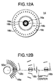
- the support beam 76a is constituted by the first beam 76b and the second beam 76c which are provided to extend in the directions opposite to each other, so that no gap center offset is generated intrinsically, while only a slight gap center offset due to an assembly error is generated. Therefore, as shown in Figs. 12A and 12B, the sectors 18a, 18b, 18c ... on the respective tracks 16a, 16b, 16c ... are formed substantially in parallel with the gap center. As a result, vertical components increase when the magnetic gap 52c runs across the sectors 18a, 18b, 18c ..., so that the deterioration of the electromagnetic conversion efficiency is restrained. In addition, even if a head having a plurality of magnetic gaps is used, the deterioration of the electromagnetic conversion efficiency is reduced.
- the magnetic pole pad 52a it is possible to dispose the magnetic pole pad 52a on the gap center easily even in the case where the length of the first beams 76b and 76b is made substantially equal to the lateral width of the adapter 64. Accordingly, it is possible to apply the support structure directly to a general-purpose floppy disk. In addition, it is not necessary to enlarge the window width, so that there is less fear of contamination on the surface of the magnetic disk 14 due to the invasion of dust or the like. In addition, the window can be formed symmetrically with respect to the gap center, so that no complicated opening/closing mechanism is required.
- each of the support beams 76a and 76a is constituted by the first and second beams 76b and 76c which are provided to extend in the directions opposite to each other, the support structure has a feature that the fluctuations in counter torque generated in the contact magnetic head 50 due to the fluctuations in the Z-height is reduced.
- the whole length of the first beams 76b and 76b is 3.5 mm
- fluctuations in the load Na applied to the magnetic pole pad 52a due to the fluctuations in the Z-height, and fluctuations in the load Ni applied to the auxiliary pads 52b and 52b also due to the fluctuations in the Z-height are obtained by arithmetic calculation.
- the results of calculation are shown in the following Table 2.
- a predetermined pressure force is given to the contact magnetic head 50 from its upper surface by the pivot spring 68, and then can be adjusted easily by controlling the shapes of the arm portion 68b, the load giving beam 68c, the flexible portions 68d and 68e, and the like. Accordingly, if the pressure force given by the pivot siring 68 is optimized in accordance with the friction coefficient on the surface of the magnetic recording medium, the up/down vibration of the support beams 76a and 76a due to the friction can be restrained, so that the self-induced vibration of the contact magnetic head 50 is also restrained.
- the present invention is not limited to the above-mentioned embodiment at all, but may be modified variously within the gist of the present invention.
- the application range of the present invention is not limited to such a support structure for a floppy disk at all.
- the present invention may be applied to a support structure for a magnetic tape, or a support structure for a hard disk in which an in-line system is adopted.
- the contact magnetic head 50 may be supported by one support beam 76a or three or more support beams 76a.
- the MR head may be supported by two support beams 76a, and each of the support beams 76a may be provided with two electrodes insulating from each other.
- the MR head may be supported by four support beams 76a which are independent of one another.
- the support beams 76a and 76a are provided to extend in parallel with the magnetic recording medium in the no-load state, the support beams 76a and 76a may be bent suitably so as to extend obliquely downward with respect to the magnetic recording medium.
- the support beam 76a is constituted by two sub-beams which are the first and second beams 76b and 76c, a support beam in which three or more sub-beams are connected zigzag may be used as the support beam 76a.
- the width and length of the support beam, the size and number of the through hole and the like may be adjusted to obtain a predetermined spring constant in the same manner as in the above-mentioned embodiment.
- the support beam 76a is provided to extend in the running direction of the magnetic disk, the extending direction of the support beam 76a is not limited to this, but may be a direction perpendicular to the running direction of the magnetic recording medium.
- the support beams 76a are connected to each other by bridges at the two places, that is, at the centers and at the tips, the first beams 76a may be connected by three or more bridges, or the second beams may be connected by one or more bridges.
- pivot spring 68 has the arm portions 68b provided to extend in the directions opposite to each other and the load giving beam 68c in the above-mentioned embodiment, a pivot spring constituted only by a load giving beam may be provided to extend from the left or right arm portion 64d or 64e of the adapter 64 toward the contact magnetic head 50.
- the flexible portions provided in the pivot spring 68 are not limited to those which are bent into a reclined-U-shape.
- flexible portions bent into a U-shape may be provided.
- through holes are provided so as to form the flexible portions near the base end and/or tip of the arm portion 68b, or those portions are reduced in thickness to form the flexible portions thereat.
- the structure for supporting a contact magnetic head having a contact pad with a magnetic pole, the structure constituted by a support having a support beam formed from elastic material and for supporting the contact magnetic head, and a contact pressure giving means for giving pressure to a contact surface between the contact pad and a magnetic recording medium
- the support beam is constituted by first and second beams provided to extend in the directions opposite to each other, so that there is an effect that it is difficult to produce a gap center offset.
- it is not necessary to widen the window width, so that there is an effect that contamination on the surface of the magnetic recording medium is restrained. Further, there is an effect that the support structure can be easily applied also to a magnetic recording medium having a narrow window.
- the fluctuations in a contact load due to the fluctuations in Z-height is reduced by the support beam having the first and second beams provided to extend in the directions opposite to each other and the contact pressure giving means, so that there is an effect that abrasion of the magnetic pole pad is restrained and contact running is stabilized. Further, if the pressure force given by the contact pressure giving means is optimized, self-induced vibration due to the friction between the contact pad and the magnetic recording medium is also restrained.
- the contact pressure giving means has arm portions and a load giving beam which are provided to extend in the directions opposite to each other, there is an effect that it becomes easy to attach both the contact pressure giving means and the support into a narrow space of an adapter.
- a thin-film-type contact magnetic head can be applied to recording/reproducing not only a general-purpose floppy disk but also a magnetic recording medium which is smaller than the general-purpose floppy disk.
- the recording density of the floppy disk can be increased on a large scale.
- the present invention has great industrial effects.
Landscapes
- Supporting Of Heads In Record-Carrier Devices (AREA)
Abstract
Description
| Z-height (µm) | | Na (×10-3N) | Ni×2 (×10-3N) |
| 152.4 | 2.11 | 1.42 | 0.69 |
| 304.8 | 1.47 | 0.87 | 0.60 |
| 457.2 | 0.83 | 0.32 | 0.51 |
| Z-height (µm) | | Na (×10-3N) | Ni×2 (×10-3N) |
| 152.4 | 2.25 | 1.01 | 1.24 |
| 304.8 | 1.47 | 0.65 | 0.82 |
| 457.2 | 0.69 | 0.29 | 0.40 |
Claims (7)
- A structure (60) for supporting a contact magnetic head (50) having a contact pad (52a) with a magnetic pole, said structure comprising:a support (70) having a support beam (76a) formed from elastic material, for supporting said contact magnetic head (50); anda contact pressure giving means for giving pressure to a contact surface between said contact pad and a magnetic recording medium;
wherein said support beam (76a) comprises:a first beam (76b) anda second beam (76c) provided to have a base end near a tip of said first beam (76b) and extend from said base end in a direction opposite to said first beam (76b). - The structure (60) for supporting a contact magnetic head (50) according to claim 1, wherein said support (60) comprises two said support beams (76a, 76a) for supporting said contact magnetic head.
- The structure (60) for supporting a contact magnetic head (50) according to claim 2, further comprising at least one cross (72f, 72g) beam for connecting said two support beams (76a, 76a).
- The structure (60) for supporting a contact magnetic head (50) according to claim 3, wherein one of said cross beams (72g) connects vicinities of tips of said respective first beams (76b, 76b).
- The structure (60) for supporting a contact magnetic head (50) according to claim 1, wherein said contact pressure giving means comprises: an arm portion (68b); and a load giving beam (68c) provided to have a base end near a tip of said arm portion (68b) and extend from said base end in a direction opposite to said arm portion.
- The structure (60) for supporting a contact magnetic head (50) according to claim 5, further comprising a flexible portion (68d) provided near at least one of a base end and tip of said arm portion (68b).
- The structure (60) for supporting a contact magnetic head (50) according to claim 6, wherein said flexible portion (68d) is formed by bending said arm portion (68b) sideways.
Applications Claiming Priority (2)
| Application Number | Priority Date | Filing Date | Title |
|---|---|---|---|
| JP29016999A JP2001110158A (en) | 1999-10-12 | 1999-10-12 | Contact type magnetic head support structure |
| JP29016999 | 1999-10-12 |
Publications (2)
| Publication Number | Publication Date |
|---|---|
| EP1093117A2 true EP1093117A2 (en) | 2001-04-18 |
| EP1093117A3 EP1093117A3 (en) | 2001-08-29 |
Family
ID=17752653
Family Applications (1)
| Application Number | Title | Priority Date | Filing Date |
|---|---|---|---|
| EP00101001A Withdrawn EP1093117A3 (en) | 1999-10-12 | 2000-01-19 | Contact magnetic head supporting structure |
Country Status (2)
| Country | Link |
|---|---|
| EP (1) | EP1093117A3 (en) |
| JP (1) | JP2001110158A (en) |
Family Cites Families (4)
| Publication number | Priority date | Publication date | Assignee | Title |
|---|---|---|---|---|
| JPS5830667B2 (en) * | 1979-04-21 | 1983-06-30 | 電気化学工業株式会社 | magnetic head support device |
| US4302789A (en) * | 1980-02-08 | 1981-11-24 | Magnetic Peripherals Inc. | Disc memory head arm lift mechanism |
| JPH06349221A (en) * | 1993-06-10 | 1994-12-22 | Hitachi Ltd | Magnetic head slider and magnetic disc device |
| JPH09198823A (en) * | 1996-01-11 | 1997-07-31 | Res Dev Corp Of Japan | Contact magnetic head support structure |
-
1999
- 1999-10-12 JP JP29016999A patent/JP2001110158A/en active Pending
-
2000
- 2000-01-19 EP EP00101001A patent/EP1093117A3/en not_active Withdrawn
Also Published As
| Publication number | Publication date |
|---|---|
| JP2001110158A (en) | 2001-04-20 |
| EP1093117A3 (en) | 2001-08-29 |
Similar Documents
| Publication | Publication Date | Title |
|---|---|---|
| US5956209A (en) | Integrated suspension flexure having a compliant tip termination platform | |
| EP0591954B1 (en) | Magnetic head suspension assembly fabricated with integral load beam and flexure | |
| US6943991B2 (en) | Suspension design for the co-located PZT micro-actuator | |
| US6950288B2 (en) | Integrated method and device for a dual stage micro-actuator and suspension design for the hard disk driver | |
| US5873159A (en) | Method of manufacturing a transducer suspension system | |
| US5818662A (en) | Static attitude and stiffness control for an integrated suspension | |
| US6597539B1 (en) | Suspension assembly for supporting a read/write head over a rotating storage disk with dynamically adjustable fly height | |
| US20040181932A1 (en) | System and method for manufacturing a hard disk drive suspension flexure and for preventing damage due to electrical arcing | |
| EP0361658A1 (en) | Magnetic recording apparatus with magnetic head air bearing slider | |
| US7614136B2 (en) | Method of producing a framing assembly | |
| US5126903A (en) | Combination of a magnetic head and a magnetic head supporting device | |
| US20010053050A1 (en) | Disc drive with improved head pitch adjustment | |
| JPH0887846A (en) | Suspension system | |
| US6487047B1 (en) | Trace interconnect array having increased bandwidth by selective etching of traces and dielectric substrate | |
| US5978176A (en) | Magnetic head for a magnetic disk having a slider with indented portions for providing heat dissipation | |
| US7292411B2 (en) | Disk head suspension arm having comb receiving portion | |
| US7433156B2 (en) | Flexure for minimizing fly height modulation of near-contact recording sliders in a disk drive | |
| EP1093117A2 (en) | Contact magnetic head supporting structure | |
| US20030002217A1 (en) | Head suspension assembly, disk device, and head suspension assembly manufacturing method | |
| US7511924B1 (en) | Conductor assembly for reducing track misregistration in a disk drive | |
| US20230206944A1 (en) | Head suspension assembly and disk device | |
| US20060098348A1 (en) | Microactuator, head gimbal assembly and magnetic disk drive | |
| US6967819B1 (en) | Head suspension with chip as structural element | |
| JP2793580B2 (en) | Thin film magnetic head | |
| JP2000215629A (en) | Contact type magnetic head support structure |
Legal Events
| Date | Code | Title | Description |
|---|---|---|---|
| PUAI | Public reference made under article 153(3) epc to a published international application that has entered the european phase |
Free format text: ORIGINAL CODE: 0009012 |
|
| AK | Designated contracting states |
Kind code of ref document: A2 Designated state(s): AT BE CH CY DE DK ES FI FR GB GR IE IT LI LU MC NL PT SE |
|
| AX | Request for extension of the european patent |
Free format text: AL;LT;LV;MK;RO;SI |
|
| PUAL | Search report despatched |
Free format text: ORIGINAL CODE: 0009013 |
|
| AK | Designated contracting states |
Kind code of ref document: A3 Designated state(s): AT BE CH CY DE DK ES FI FR GB GR IE IT LI LU MC NL PT SE |
|
| AX | Request for extension of the european patent |
Free format text: AL;LT;LV;MK;RO;SI |
|
| AKX | Designation fees paid | ||
| REG | Reference to a national code |
Ref country code: DE Ref legal event code: 8566 |
|
| STAA | Information on the status of an ep patent application or granted ep patent |
Free format text: STATUS: THE APPLICATION IS DEEMED TO BE WITHDRAWN |
|
| 18D | Application deemed to be withdrawn |
Effective date: 20020302 |