EP1093087A2 - Removing chroma noise from digital images by using variable shape pixel neighborhood regions - Google Patents
Removing chroma noise from digital images by using variable shape pixel neighborhood regions Download PDFInfo
- Publication number
- EP1093087A2 EP1093087A2 EP00203315A EP00203315A EP1093087A2 EP 1093087 A2 EP1093087 A2 EP 1093087A2 EP 00203315 A EP00203315 A EP 00203315A EP 00203315 A EP00203315 A EP 00203315A EP 1093087 A2 EP1093087 A2 EP 1093087A2
- Authority
- EP
- European Patent Office
- Prior art keywords
- pixel
- interest
- pixels
- value
- map
- Prior art date
- Legal status (The legal status is an assumption and is not a legal conclusion. Google has not performed a legal analysis and makes no representation as to the accuracy of the status listed.)
- Granted
Links
Images

Classifications
-
- G—PHYSICS
- G06—COMPUTING OR CALCULATING; COUNTING
- G06T—IMAGE DATA PROCESSING OR GENERATION, IN GENERAL
- G06T5/00—Image enhancement or restoration
- G06T5/20—Image enhancement or restoration using local operators
Definitions
- the present invention relates to providing smoothed digital images with reduced noise.
- noise found in digital camera images appears as low frequency, colored blobs in regions of low spatial frequency, for example, a person's face. These blobs, a type of chroma noise, produce a mottled appearance in an otherwise spatially flat region. These colored blobs are irregularly shaped and are typically 5 to 25, or more, pixels wide in a given direction.
- chroma noise reduction Another very common approach to chroma noise reduction is to simply use standard grayscale image noise reduction techniques on each color channel of the image, in effect, treating each color channel as a separate grayscale image. By treating a full-color image as three, unrelated grayscale images, any interactions or correlations between the color channels are ignored.
- the inherent relationships between the color planes of a digital image can be used to perform more effective chroma noise cleaning, for example, by transforming the image into a different color space that permits for easier separation of image noise from genuine scene content.
- CFA color filter array
- the present invention overcomes the limitation of the "chroma blur trick" by first identifying all of the edges and boundaries in the image and then permitting each calculation neighborhood region to adaptively grow until it encounters an edge or boundary. Consequently, color bleed is avoided while still permitting the use of large area blurring operations to eliminate chroma noise artifacts.
- a novel aspect of this invention is the use of a locally adaptive, variable sized calculation neighborhood region that keys off of an edge feature map to permit the maximum amount of chroma noise removal without significant degradation to genuine scene detail.
- noise cleaning algorithms for digital images are well known, the present description will be directed in particular to elements forming part of, or cooperating more directly with, apparatus and method in accordance with the present invention. Elements not specifically shown or described herein may be selected from those known in the art. Although the present invention will be described in relation to a digital image produced by an electronic camera, it will be understood by those skilled in the art that the present invention is not limited to such image product devices and can use original digital images from other sources.
- block 10 is the original image.
- the image is converted to a luminance ⁇ chrominance space, such as CIELAB.
- CIELAB is the preferred color space, other color spaces that can be used in accordance with the present invention will suggest themselves to those skilled in the art.
- Blocks 14, 16, and 18 create a map of features, or edge map, from the luminance - chrominance data.
- four edge detector filters are convolved with each channel and the results summed to create the edge map. The four filters are "h” for horizontal, "v” for vertical, "s" for slash and "b” for backslash.
- g(x)
- x is either the luminance channel, L*, or one of the chrominance channels, a* or b*
- **" is the two-dimensional convolution operation, and absolute values of the components are added together.
- the four edge detector kernels are 5x5 truncated pyramid filters that were chosen to provide some robustness when used with noisy data. Larger kernels could be used for even more noise suppression.
- the kernels used here are:
- the final composite edge map, "g" is created by summing together the three channel edge maps.
- g g(L*) + g(a*) + g(b*) Since the individual components are already all positive values, there is not need to use additional absolute value operations in conjunction with this summation.
- a threshold value is determined. Typically, for an initial estimate, one chooses a flat region of the image and calculates the standard deviation (stdv) of the edge map values in this region. Three times the standard deviation (3 stdv) becomes the threshold. If this algorithm is being run interactively, this threshold could be one of the knobs given to the user. If it is found that for a given application the threshold does not significantly change from image to image, the threshold can be determined once, off-line, and then left as a fixed value for future use.
- the chrominance channels, a* and b*, are now smoothed. In other words they are noise cleaned.
- the corresponding edge map value is taken to be the reference value.
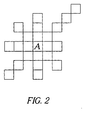
- the algorithm moves out in each of the eight compass directions, N, NE, E, SE, S, SW, W, NW, one pixel at a time, examining the edge map values. If the difference between an edge map value and the reference value is less than the threshold, that pixel is added to the smoothing neighborhood region and the algorithm continues. Once an edge map value is reached that differs from the reference value by more than the threshold, the growth of the smoothing neighborhood region in that compass direction is stopped.
- FIG. 2 illustrates a typical smoothing neighborhood region after all compass directions have been examined. In this arrangement, eight directions are shown since there are eight contiguous pixels surrounding the pixel of interest. However, a contiguous neighborhood region is not a requirement of this invention. Note that this neighborhood region will be variable in shape and size.
- the a* and b* channel values are averaged and these averages replace the a* and b* channel values for pixel A in FIG. 2. Each pixel in the image is processed in this way. In block 26, FIG. 1, the final image is converted back to the original color space.
- the maximum possible direction of neighborhood region expansion in any given compass direction can be restricted to prevent huge neighborhood regions from being used in large flat regions.
- Such a maximum radius value might be in the range from 50 to 100 pixels.
- the present invention can be embodied in a software program provided in a computer program product, having a computer readable storage medium having a computer program stored thereon for removing noise on a pixel by pixel basis from pixels of a digital image.
- the computer program performs the steps of:
- the computer readable storage medium may comprise, for example, magnetic storage media, such as magnetic disks (such as a floppy disk) or magnetic tape; optical storage media such as an optical disk, optical tape or machine readable memory (RAM), or read only memory (ROM); or any other physical device or medium.
- magnetic storage media such as magnetic disks (such as a floppy disk) or magnetic tape
- optical storage media such as an optical disk, optical tape or machine readable memory (RAM), or read only memory (ROM); or any other physical device or medium.
Landscapes
- Physics & Mathematics (AREA)
- General Physics & Mathematics (AREA)
- Engineering & Computer Science (AREA)
- Theoretical Computer Science (AREA)
- Facsimile Image Signal Circuits (AREA)
- Image Processing (AREA)
- Processing Of Color Television Signals (AREA)
Abstract
Description

Claims (4)
- A method for removing noise on a pixel by pixel basis from pixels of a digital image comprising the steps of:(a) producing a map of features in the digital image;(b) storing an original value of the pixel of interest from the map of features;(c) using values of features from the map to determine a variable shape neighborhood region of cleaning pixels with respect to the original value of the pixel of interest;(d) using the neighborhood region of cleaning pixels and the value of the pixel of interest to change the original value of the pixel of interest in the digital image so that it has been noise cleaned; and(e) repeating steps (a)-(d) for other pixels of interest.
- The method of claim 1 wherein the neighboring contiguous pixels are disposed along predetermined directions which pass through the pixel of interest and the extent of the pixels along each direction are determined by the value of the features along such direction compared to the original pixel value.
- The method of claim 1 wherein the neighboring contiguous pixels are disposed along predetermined directions which pass through the pixel of interest and the extent of the pixels along each direction are determined by the value of an edge along such direction.
- A computer program product, comprising:a computer readable storage medium having a computer program stored thereon for removing noise on a pixel by pixel basis from pixels of a digital image for performing the steps of:(a) producing a map of features in the digital image;(b) storing an original value of the pixel of interest from the map of features;(c) using values of features from the map to determine a variable shape neighborhood region of cleaning pixels with respect to the original value of the pixel of interest;(d) using the neighborhood region of cleaning pixels and the value of the pixel of interest to change the original value of the pixel of interest in the digital image so that it has been noise cleaned; and(e) repeating steps (a)-(d) for other pixels of interest.
Applications Claiming Priority (2)
| Application Number | Priority Date | Filing Date | Title |
|---|---|---|---|
| US09/415,374 US6621937B1 (en) | 1999-10-08 | 1999-10-08 | Removing chroma noise from digital images by using variable shape pixel neighborhood regions |
| US415374 | 1999-10-08 |
Publications (3)
| Publication Number | Publication Date |
|---|---|
| EP1093087A2 true EP1093087A2 (en) | 2001-04-18 |
| EP1093087A3 EP1093087A3 (en) | 2002-08-21 |
| EP1093087B1 EP1093087B1 (en) | 2004-08-04 |
Family
ID=23645437
Family Applications (1)
| Application Number | Title | Priority Date | Filing Date |
|---|---|---|---|
| EP00203315A Expired - Lifetime EP1093087B1 (en) | 1999-10-08 | 2000-09-25 | Removing chroma noise from digital images by using variable shape pixel neighborhood regions |
Country Status (4)
| Country | Link |
|---|---|
| US (1) | US6621937B1 (en) |
| EP (1) | EP1093087B1 (en) |
| JP (1) | JP4755749B2 (en) |
| DE (1) | DE60012649T2 (en) |
Cited By (8)
| Publication number | Priority date | Publication date | Assignee | Title |
|---|---|---|---|---|
| WO2002030100A3 (en) * | 2000-10-06 | 2002-06-13 | Xcounter Ab | Noise reduction in images, by adding a pixel to a region (r), adding surrounding pixel pairs to the region if they fulfil a condition and determine a mean value for the region |
| EP1511294A3 (en) * | 2003-08-28 | 2007-05-30 | Sharp Kabushiki Kaisha | Chrominance smoothing |
| WO2007026304A3 (en) * | 2005-09-02 | 2007-06-07 | Koninkl Philips Electronics Nv | A filter for adaptively extracting a local illumination |
| EP1991008A4 (en) * | 2006-02-27 | 2012-04-18 | Nikon Corp | Image processing device for correcting image massive feeling, image processing program, image processing method, and electronic camera |
| CN102934422A (en) * | 2010-06-07 | 2013-02-13 | 奥林巴斯医疗株式会社 | Signal processing device and still image generation method |
| US9129393B2 (en) | 2011-03-15 | 2015-09-08 | Stmircoelectronics S.R.L. | Image chroma noise reduction in the bayer domain |
| US9135681B2 (en) | 2011-09-09 | 2015-09-15 | Stmicroelectronics S.R.L. | Image chroma noise reduction |
| US9549194B2 (en) | 2012-01-09 | 2017-01-17 | Dolby Laboratories Licensing Corporation | Context based inverse mapping method for layered codec |
Families Citing this family (22)
| Publication number | Priority date | Publication date | Assignee | Title |
|---|---|---|---|---|
| US7031548B2 (en) * | 2001-10-04 | 2006-04-18 | Hewlett-Packard Development Company, L.P. | Method and apparatus for filtering noise from a digital image |
| JP2004127064A (en) | 2002-10-04 | 2004-04-22 | Konica Minolta Holdings Inc | Image processing method, image processor, image processing program and image recording device |
| US20040194123A1 (en) * | 2003-03-28 | 2004-09-30 | Eastman Kodak Company | Method for adapting digital cinema content to audience metrics |
| US7466868B2 (en) * | 2003-10-03 | 2008-12-16 | Adobe Systems Incorporated | Determining parameters for adjusting images |
| US7412105B2 (en) * | 2003-10-03 | 2008-08-12 | Adobe Systems Incorporated | Tone selective adjustment of images |
| US8120703B2 (en) * | 2005-09-08 | 2012-02-21 | Silicon Image/BSTZ | Source-adaptive video deinterlacer |
| US7982798B2 (en) | 2005-09-08 | 2011-07-19 | Silicon Image, Inc. | Edge detection |
| WO2008076566A1 (en) * | 2006-12-20 | 2008-06-26 | Anchor Bay Technologies, Inc. | Noise cancellation |
| JP4858610B2 (en) * | 2007-02-28 | 2012-01-18 | 株式会社ニコン | Image processing method |
| US7844127B2 (en) * | 2007-03-30 | 2010-11-30 | Eastman Kodak Company | Edge mapping using panchromatic pixels |
| JP5349790B2 (en) * | 2007-11-16 | 2013-11-20 | キヤノン株式会社 | Image processing apparatus, image processing method, and program |
| US8090183B2 (en) * | 2009-03-12 | 2012-01-03 | Visiongate, Inc. | Pattern noise correction for pseudo projections |
| CN102067171B (en) * | 2008-06-19 | 2013-02-13 | 马维尔国际贸易有限公司 | Segmentation edge enhancement method and system |
| US8559746B2 (en) * | 2008-09-04 | 2013-10-15 | Silicon Image, Inc. | System, method, and apparatus for smoothing of edges in images to remove irregularities |
| CN102349107B (en) * | 2009-02-10 | 2015-02-18 | 晶像股份有限公司 | Block noise detection and filtering |
| US8274583B2 (en) * | 2009-06-05 | 2012-09-25 | Apple Inc. | Radially-based chroma noise reduction for cameras |
| CN102714690A (en) * | 2009-09-04 | 2012-10-03 | 布瑞特布里克有限公司 | Mobile wide-angle video recording system |
| GB2487149B (en) * | 2009-10-13 | 2015-10-14 | Canon Kk | Method and apparatus for reducing the effects of noise in image signals |
| US9047665B2 (en) | 2013-08-21 | 2015-06-02 | Panasonic Intellectual Property Management Co., Ltd. | Image processing apparatus |
| JP6671943B2 (en) * | 2015-03-03 | 2020-03-25 | キヤノン株式会社 | Image processing apparatus, image processing method, and program |
| US11069054B2 (en) | 2015-12-30 | 2021-07-20 | Visiongate, Inc. | System and method for automated detection and monitoring of dysplasia and administration of immunotherapy and chemotherapy |
| CN114078099A (en) * | 2021-11-23 | 2022-02-22 | 中国银行股份有限公司 | Image significance detection method and device based on histogram gray feature pair |
Family Cites Families (8)
| Publication number | Priority date | Publication date | Assignee | Title |
|---|---|---|---|---|
| DE4329672C1 (en) * | 1993-09-02 | 1994-12-01 | Siemens Ag | Method for suppressing noise in digital images |
| FR2737034A1 (en) * | 1995-07-21 | 1997-01-24 | Philips Electronique Lab | METHOD FOR SPATIALLY PROCESSING A DIGITAL IMAGE FOR NOISE REDUCTION, AND DEVICE USING THE SAME |
| JP3462960B2 (en) * | 1996-08-02 | 2003-11-05 | 株式会社日立製作所 | Image processing method |
| EP0845717B1 (en) * | 1996-11-29 | 2002-01-30 | Kabushiki Kaisha Toshiba | Image processing apparatus with smoothing feature |
| US5845017A (en) * | 1996-12-17 | 1998-12-01 | Eastman Kodak Company | Digital image processing method for degraining of film images using distance weighted averaging of target pixel code values |
| US6229578B1 (en) | 1997-12-08 | 2001-05-08 | Intel Corporation | Edge-detection based noise removal algorithm |
| US6108455A (en) * | 1998-05-29 | 2000-08-22 | Stmicroelectronics, Inc. | Non-linear image filter for filtering noise |
| US6907144B1 (en) * | 1999-10-06 | 2005-06-14 | Eastman Kodak Company | Noise reduction method, apparatus, and program for digital image processing |
-
1999
- 1999-10-08 US US09/415,374 patent/US6621937B1/en not_active Expired - Lifetime
-
2000
- 2000-09-25 DE DE60012649T patent/DE60012649T2/en not_active Withdrawn - After Issue
- 2000-09-25 EP EP00203315A patent/EP1093087B1/en not_active Expired - Lifetime
- 2000-10-10 JP JP2000308659A patent/JP4755749B2/en not_active Expired - Fee Related
Cited By (10)
| Publication number | Priority date | Publication date | Assignee | Title |
|---|---|---|---|---|
| WO2002030100A3 (en) * | 2000-10-06 | 2002-06-13 | Xcounter Ab | Noise reduction in images, by adding a pixel to a region (r), adding surrounding pixel pairs to the region if they fulfil a condition and determine a mean value for the region |
| US6879732B1 (en) | 2000-10-06 | 2005-04-12 | Xcounter Ab | Noise reduction in images |
| EP1511294A3 (en) * | 2003-08-28 | 2007-05-30 | Sharp Kabushiki Kaisha | Chrominance smoothing |
| WO2007026304A3 (en) * | 2005-09-02 | 2007-06-07 | Koninkl Philips Electronics Nv | A filter for adaptively extracting a local illumination |
| EP1991008A4 (en) * | 2006-02-27 | 2012-04-18 | Nikon Corp | Image processing device for correcting image massive feeling, image processing program, image processing method, and electronic camera |
| CN102934422A (en) * | 2010-06-07 | 2013-02-13 | 奥林巴斯医疗株式会社 | Signal processing device and still image generation method |
| CN102934422B (en) * | 2010-06-07 | 2015-05-27 | 奥林巴斯医疗株式会社 | Signal processing device and still image generation method |
| US9129393B2 (en) | 2011-03-15 | 2015-09-08 | Stmircoelectronics S.R.L. | Image chroma noise reduction in the bayer domain |
| US9135681B2 (en) | 2011-09-09 | 2015-09-15 | Stmicroelectronics S.R.L. | Image chroma noise reduction |
| US9549194B2 (en) | 2012-01-09 | 2017-01-17 | Dolby Laboratories Licensing Corporation | Context based inverse mapping method for layered codec |
Also Published As
| Publication number | Publication date |
|---|---|
| JP2001155148A (en) | 2001-06-08 |
| JP4755749B2 (en) | 2011-08-24 |
| DE60012649D1 (en) | 2004-09-09 |
| EP1093087A3 (en) | 2002-08-21 |
| US6621937B1 (en) | 2003-09-16 |
| EP1093087B1 (en) | 2004-08-04 |
| DE60012649T2 (en) | 2005-08-11 |
Similar Documents
| Publication | Publication Date | Title |
|---|---|---|
| EP1093087B1 (en) | Removing chroma noise from digital images by using variable shape pixel neighborhood regions | |
| JP4541679B2 (en) | A method to reduce computation time when removing color aliasing artifacts from color digital images | |
| EP1038159B1 (en) | A new edge-detection based noise removal algorithm | |
| US6934056B2 (en) | Noise cleaning and interpolating sparsely populated color digital image using a variable noise cleaning kernel | |
| US8559744B2 (en) | Method for processing a digital object and related system | |
| CN101675454B (en) | Edge drawing with full-color pixels | |
| EP1150248A2 (en) | Digital image processing method for edge contrast enhancement using wavelet transform | |
| WO2001026053A1 (en) | Noise reduction method, apparatus, and program for digital image processing | |
| EP1093088B1 (en) | A region growing based noise reduction method for digital images | |
| EP1202220B1 (en) | Method for removing color aliasing artifacts from color digital images | |
| JP2004040247A (en) | Image processing apparatus and control method thereof | |
| US6927804B2 (en) | Reducing color aliasing artifacts from color digital images | |
| JP2000023173A (en) | Noise elimination method for solid-state color image pickup device | |
| EP1083737A2 (en) | Removing color moire patterns from digital images having known chromaticities | |
| US6795586B1 (en) | Noise cleaning and interpolating sparsely populated color digital image | |
| KR100213235B1 (en) | Filtering method and the low pass filter for adaptable edge low pass filter | |
| KR100190039B1 (en) | Apparatus and method of extending high resolution image | |
| KR100839922B1 (en) | Apparatus and method for removing color noise using adaptive mean filter | |
| KR100821939B1 (en) | Image Noise Reduction Device and Method | |
| Adams Jr et al. | Edge-Based Noise Cleaning of Chrominance Information in Color Images | |
| KR100192777B1 (en) | Median filter having multiple window size | |
| KR100222278B1 (en) | Blocking effect removing method | |
| Hossain et al. | AN EFFICIENT APPROACH OF IMAGE RESTORATION USING MEAN INTENSITY CORRELATION OF NEIGHBORING PIXELS | |
| WO2017167382A1 (en) | Improvements in or relating to filters |
Legal Events
| Date | Code | Title | Description |
|---|---|---|---|
| PUAI | Public reference made under article 153(3) epc to a published international application that has entered the european phase |
Free format text: ORIGINAL CODE: 0009012 |
|
| AK | Designated contracting states |
Kind code of ref document: A2 Designated state(s): AT BE CH CY DE DK ES FI FR GB GR IE IT LI LU MC NL PT SE |
|
| AX | Request for extension of the european patent |
Free format text: AL;LT;LV;MK;RO;SI |
|
| PUAL | Search report despatched |
Free format text: ORIGINAL CODE: 0009013 |
|
| AK | Designated contracting states |
Kind code of ref document: A3 Designated state(s): AT BE CH CY DE DK ES FI FR GB GR IE IT LI LU MC NL PT SE |
|
| AX | Request for extension of the european patent |
Free format text: AL;LT;LV;MK;RO;SI |
|
| 17P | Request for examination filed |
Effective date: 20030120 |
|
| 17Q | First examination report despatched |
Effective date: 20030219 |
|
| AKX | Designation fees paid |
Designated state(s): DE FR GB |
|
| GRAP | Despatch of communication of intention to grant a patent |
Free format text: ORIGINAL CODE: EPIDOSNIGR1 |
|
| GRAS | Grant fee paid |
Free format text: ORIGINAL CODE: EPIDOSNIGR3 |
|
| GRAA | (expected) grant |
Free format text: ORIGINAL CODE: 0009210 |
|
| AK | Designated contracting states |
Kind code of ref document: B1 Designated state(s): DE FR GB |
|
| REG | Reference to a national code |
Ref country code: GB Ref legal event code: FG4D |
|
| REG | Reference to a national code |
Ref country code: IE Ref legal event code: FG4D |
|
| REF | Corresponds to: |
Ref document number: 60012649 Country of ref document: DE Date of ref document: 20040909 Kind code of ref document: P |
|
| ET | Fr: translation filed | ||
| PLBE | No opposition filed within time limit |
Free format text: ORIGINAL CODE: 0009261 |
|
| STAA | Information on the status of an ep patent application or granted ep patent |
Free format text: STATUS: NO OPPOSITION FILED WITHIN TIME LIMIT |
|
| REG | Reference to a national code |
Ref country code: IE Ref legal event code: MM4A |
|
| 26N | No opposition filed |
Effective date: 20050506 |
|
| PGFP | Annual fee paid to national office [announced via postgrant information from national office to epo] |
Ref country code: GB Payment date: 20050809 Year of fee payment: 6 |
|
| PGFP | Annual fee paid to national office [announced via postgrant information from national office to epo] |
Ref country code: FR Payment date: 20050902 Year of fee payment: 6 |
|
| PGFP | Annual fee paid to national office [announced via postgrant information from national office to epo] |
Ref country code: DE Payment date: 20050930 Year of fee payment: 6 |
|
| PG25 | Lapsed in a contracting state [announced via postgrant information from national office to epo] |
Ref country code: DE Free format text: LAPSE BECAUSE OF THE APPLICANT RENOUNCES Effective date: 20060221 |
|
| GBPC | Gb: european patent ceased through non-payment of renewal fee |
Effective date: 20060925 |
|
| REG | Reference to a national code |
Ref country code: FR Ref legal event code: ST Effective date: 20070531 |
|
| PG25 | Lapsed in a contracting state [announced via postgrant information from national office to epo] |
Ref country code: GB Free format text: LAPSE BECAUSE OF NON-PAYMENT OF DUE FEES Effective date: 20060925 |
|
| PG25 | Lapsed in a contracting state [announced via postgrant information from national office to epo] |
Ref country code: FR Free format text: LAPSE BECAUSE OF NON-PAYMENT OF DUE FEES Effective date: 20061002 |