EP1092957A2 - Displacement transducer - Google Patents
Displacement transducer Download PDFInfo
- Publication number
- EP1092957A2 EP1092957A2 EP00203568A EP00203568A EP1092957A2 EP 1092957 A2 EP1092957 A2 EP 1092957A2 EP 00203568 A EP00203568 A EP 00203568A EP 00203568 A EP00203568 A EP 00203568A EP 1092957 A2 EP1092957 A2 EP 1092957A2
- Authority
- EP
- European Patent Office
- Prior art keywords
- transducer
- value
- values
- output
- calculating
- Prior art date
- Legal status (The legal status is an assumption and is not a legal conclusion. Google has not performed a legal analysis and makes no representation as to the accuracy of the status listed.)
- Granted
Links
- 238000006073 displacement reaction Methods 0.000 title claims abstract description 25
- 238000012937 correction Methods 0.000 claims abstract description 39
- 238000000034 method Methods 0.000 claims abstract description 27
- 238000001914 filtration Methods 0.000 claims description 6
- 238000004364 calculation method Methods 0.000 claims description 4
- 230000000694 effects Effects 0.000 claims description 2
- 230000003111 delayed effect Effects 0.000 claims 1
- 238000012545 processing Methods 0.000 description 8
- 238000005259 measurement Methods 0.000 description 5
- 230000008569 process Effects 0.000 description 5
- 230000004044 response Effects 0.000 description 4
- 230000000737 periodic effect Effects 0.000 description 3
- 238000010586 diagram Methods 0.000 description 2
- 230000003595 spectral effect Effects 0.000 description 2
- 230000004075 alteration Effects 0.000 description 1
- 230000008901 benefit Effects 0.000 description 1
- 238000004040 coloring Methods 0.000 description 1
- 230000008878 coupling Effects 0.000 description 1
- 238000010168 coupling process Methods 0.000 description 1
- 238000005859 coupling reaction Methods 0.000 description 1
- 238000013461 design Methods 0.000 description 1
- 230000006870 function Effects 0.000 description 1
- 238000003754 machining Methods 0.000 description 1
- 238000004519 manufacturing process Methods 0.000 description 1
- 238000009987 spinning Methods 0.000 description 1
- 238000006467 substitution reaction Methods 0.000 description 1
- 230000001360 synchronised effect Effects 0.000 description 1
Images



Classifications
-
- G—PHYSICS
- G01—MEASURING; TESTING
- G01D—MEASURING NOT SPECIALLY ADAPTED FOR A SPECIFIC VARIABLE; ARRANGEMENTS FOR MEASURING TWO OR MORE VARIABLES NOT COVERED IN A SINGLE OTHER SUBCLASS; TARIFF METERING APPARATUS; MEASURING OR TESTING NOT OTHERWISE PROVIDED FOR
- G01D5/00—Mechanical means for transferring the output of a sensing member; Means for converting the output of a sensing member to another variable where the form or nature of the sensing member does not constrain the means for converting; Transducers not specially adapted for a specific variable
- G01D5/12—Mechanical means for transferring the output of a sensing member; Means for converting the output of a sensing member to another variable where the form or nature of the sensing member does not constrain the means for converting; Transducers not specially adapted for a specific variable using electric or magnetic means
- G01D5/244—Mechanical means for transferring the output of a sensing member; Means for converting the output of a sensing member to another variable where the form or nature of the sensing member does not constrain the means for converting; Transducers not specially adapted for a specific variable using electric or magnetic means influencing characteristics of pulses or pulse trains; generating pulses or pulse trains
- G01D5/24471—Error correction
- G01D5/24476—Signal processing
-
- G—PHYSICS
- G01—MEASURING; TESTING
- G01D—MEASURING NOT SPECIALLY ADAPTED FOR A SPECIFIC VARIABLE; ARRANGEMENTS FOR MEASURING TWO OR MORE VARIABLES NOT COVERED IN A SINGLE OTHER SUBCLASS; TARIFF METERING APPARATUS; MEASURING OR TESTING NOT OTHERWISE PROVIDED FOR
- G01D5/00—Mechanical means for transferring the output of a sensing member; Means for converting the output of a sensing member to another variable where the form or nature of the sensing member does not constrain the means for converting; Transducers not specially adapted for a specific variable
- G01D5/12—Mechanical means for transferring the output of a sensing member; Means for converting the output of a sensing member to another variable where the form or nature of the sensing member does not constrain the means for converting; Transducers not specially adapted for a specific variable using electric or magnetic means
- G01D5/244—Mechanical means for transferring the output of a sensing member; Means for converting the output of a sensing member to another variable where the form or nature of the sensing member does not constrain the means for converting; Transducers not specially adapted for a specific variable using electric or magnetic means influencing characteristics of pulses or pulse trains; generating pulses or pulse trains
- G01D5/24471—Error correction
- G01D5/2448—Correction of gain, threshold, offset or phase control
Definitions
- This invention relates generally to displacement transducers, and more particularly to a method for correcting spin frequency noise errors associated with rotary transducers.
- Rotary encoders also referred to as angular encoders, sense rotary displacement, convert rotary information to an electric signal, and provide a digital output, which is processed to determine angular position.
- Rotary displacement transducers are used in a wide variety of applications, generalized by the occurrence of some form of rotary motion.
- a rotary displacement transducer is used to locate and track the rotary position of that motion.
- An example of a common use of rotary displacement transducers is in connection with systems that use a rotary actuator.
- a rotary displacement transducer is often mounted to a motor to determine shaft position.
- Such transducers can also be mounted to positioning tables, screw drives, gearheads, machining tools, and the like.
- a problem encountered in the use of rotary displacement transducers is spin frequency error. Manufacturing tolerances and mechanical mounting differences can cause the signal from the transducer to contain anomalies. Various filtering methods could be used, but introduce phase delay and fall short of isolating only the error component or components.
- the present application discloses a method of correcting spin frequency error in the output of a rotary displacement transducer. For each revolution of the transducer, a series of output values is stored, each output value representing a time interval between pulses of the transducer. An “inphase value” is calculated by multiplying each output value times a sin wave value, the sin wave having a period determined by the transducer resolution, and by calculating an average from the results of the multiplying step. A "quadrature value” is calculated by multiplying each output value times a cosine wave value, the cosine wave having a period determined by the transducer resolution, and by calculating an average from the results of the multiplying step.
- the inphase and quadrature values are used to calculate a magnitude and a phase value.
- the magnitude and phase values are then used to calculate a series of correction values, the correction values corresponding to points on a sin wave having a period determined by the transducer resolution and having a magnitude and phase equal to the magnitude and phase values.
- Each correction value is subtracted from a corresponding transducer output value, thereby providing corrected transducer output values. The process is repeated for each revolution of the transducer.
- An advantage of the disclosed method is that the error correction is automatic and continuous. It removes once-per-revolution error, and any or all periodic noise components, such as a twice-per-revolution noise component, electronically and in pseudo real time.
- the correction process does not compromise the integrity of the measurement data provided by the transducer. In other words, there is no phase delay or magnitude coloring associated with the measurement data provided by the transducer; only the desired frequency component or frequency components of the output signal are removed and thereby affected.
- FIGURE 1 illustrates a portion of a photofinishing system 100, which has two applications of a rotary displacement transducer.
- SLM spatial light modulator
- An example of a suitable SLM 101 is a digital micromirror device (DMD), which is an array of tiny micromirrors, each of which is individually addressable with an electronic signal to go to an "OFF" or "ON” state. Each mirror creates a pixel element of the image.
- DMD-type SLM 101 is illuminated by white light, and the "ON" or "OFF” state determines whether a given mirror (pixel element) of the image will be dark or light.
- Various modulation techniques are used to vary the intensity of each pixel element. Other types of SLM's could be used.
- a color wheel 102 is used to color the images.
- the images are used to expose a photosensitive media (such as photographic paper) carried on a transport belt 103.
- a series of different still images illuminates a series of different photographic negatives.
- a transducer is used in each of two subsystems of photofinishing system 100: a color wheel subsystem and a digital resolution translator (DRT) subsystem.
- DDT digital resolution translator
- rotary displacement transducers have a vast variety of applications, and the principles described herein can be used for rotary displacement transducers in any application.
- both rotary displacement transducers are encoders, providing a digital output.
- the color wheel 102 is a rotating wheel, driven by a motor 102a and having segments with differently colored filters.
- the segments are red, green, and blue.
- Each image generated by the display device 101 passes through the color wheel 102 as the color wheel 102 rotates.
- the position of the color wheel 102 determines the color of the image.
- the color wheel motor 102a is synchronized to the display device 101, so that as new images are generated, each is filtered with a desired color.
- a combination of differently colored images results in a full color picture having all color components.
- a color wheel transducer 109 translates the motion of the color wheel 102 into digital data that is used to control the operation of the color wheel 102. As illustrated, the color wheel transducer 109 delivers transducer data to a processor 130 that removes the spin frequency error. The corrected transducer data is delivered to closed loop feedback system 113, used to control the color wheel motor 102a via a power drive amplifier 117.
- the transport system has a transport belt 103, which carries the photosensitive media past each new image generated by the SLM 101.
- the transport belt 103 is driven by a motor 103a.
- Code wheel 104 translates the motion of the belt 103 into rotary motion
- code wheel transducer 105 translates the code wheel motion into digital information.
- This digital information is corrected by removing the spin frequency error with processor 130 and further processed by a digital resolution translator 115, so as to provide digital resolution transport (DRT) data to an image control system associated with SLM 101.
- DTR digital resolution transport
- the correction processor 130 and translator 115 could be interchanged, that is, either could be performed before the other.
- a correction processor 130 to remove spin frequency error in the output of the transducers 105 and 109.
- Two processors 130 are illustrated in FIGURE 1, one for each transducer 105 and 109. In other embodiments, a single processor could perform the correction for the output of both transducers.
- the signal emanating from transducers 105 and 109 is a complex time series waveform containing spectral position data.
- the waveform contains spin frequency error components.
- An example of spin frequency error is often referred to as "eccentricity" error.
- spin frequency error manifests itself as a noise component at the spin frequency and at potential harmonics of the fundamental spin frequency.
- a fundamental component occurs at one revolution per second.
- Harmonic noise components occur at two, three, four, etc., revolutions per second. The methods described herein can be used to remove these noise components.
- the once-per-revolution component of spin frequency noise is due to mechanical spin frequency inherent in the transducer 104 and not due to speed error.
- the once-per-revolution error is at a single sinusoidal frequency with a specific magnitude and phase that can be extracted from the complex waveform.
- the phase of this sinusoidal frequency is substantially repeatable from print to print (or more specifically, transducer revolution to revolution).
- the phase is also assumed to be independent of the speed of the transducer.
- the magnitude is less repeatable from revolution to revolution, due to variation of contact pressure, i.e., pressure from the measurement surface coupling to the transducer. This force variation affects the magnitude of the sinusoidal term. Mechanical design and proper mounting of the transducer can minimize this variation by attempting to achieve constant force between the transducer and the measurement surface.
- an error correction processor 130 removes error resulting from the spin frequency noise of the rotary displacement transducer. In general, it measures the transducer spin frequency on a continuous basis. It computes the magnitude and phase of the spin frequency error for each revolution of the transducer, and applies an alpha filtered average phase and magnitude correction.
- Processor 130 may be implemented with any general purpose processor, and is assumed to have input means, memory, and calculation circuitry for performing the method described herein.
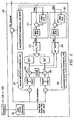
- FIGURE 2 illustrates a rotary displacement transducer 21 and either of the transducer error correction processors 130 of FIGURE 1.
- Transducer 21 may be either of the transducers 105 or 109 in FIGURE 1.
- the discussion herein of these two types of application-specific transducers is for purposes of example, and the output of any type of rotary displacement transducer 21 may be corrected with processor 130.
- transducer 21 its output signal may undergo some type of front end processing by transducer event capture electronics 22.
- This front-end processing may vary depending on the application, and may be implemented with dedicated circuitry or with programming of processor 130 in addition to that used for spin frequency error correction.
- the transducer output data, X(k) is assumed to have the spin frequency error described above.
- Processor 130 may be any general purpose processor, or one especially designed to carry out the functions described herein.
- the process flow diagram within processor 130 illustrates the programming performed by processor 130 for spin frequency error correction.
- FIGURE 3 illustrates the same processing illustrated in FIGURE 2, as performed by processor 130.
- the process steps of FIGURE 3 are identified in FIGURE 2 with functional blocks that may be implemented with electronic circuitry and/or programming.
- the steps of FIGURE 3 are repeated for each revolution. That is, new correction values are calculated and applied for each revolution of the transducer.
- the algorithm is directed to removal of spin frequency error at the fundamental frequency. Additional processing for harmonics of the error signal is described below in connection with FIGUREs 5 and 6.
- the initial error correction processing of X(k) is divided into two paths, so as to obtain two intermediate values, P and Q, which are an inphase and a quadrature value, respectively, of X(k) at the transducer frequency.
- Step 301 for the inphase value path, each value of X(k) is multiplied times a corresponding sin value to create a sin wave.
- the first sample value of X(k) would be multiplied times sin(2*pi*1/48) .
- the last value (for one revolution) would be multiplied times sin(2*pi*48/48) , which is the same as sin(2*pi) .
- the product of each X(k) value and each sin value results in a new set of 48 values, representing a sin wave with 48 points.
- Step 302 an average sin wave value is obtained by summing the sin wave values from 1 to nsample (48) and dividing by nsample (48). The result is an in phase average value, P.
- Steps 306 and 307 are analogous to Steps 301 and 302.
- Step 306 for the fphs path, each X(k) is multiplied times a cos value to create 48 cosine values. The calculation is similar to that used for Step 301, except that a cos factor is used.
- Step 307 a quadrature average value, Q, is calculated.
- the P and Q values are inphase and quadrature values of a sin wave whose period coincides with one revolution of the transducer.
- a feature of the invention is the use of the transducer resolution (counts per revolution) to determine the period of the sin wave. In the example of this description, after 48 transducer pulses, it can be assumed that the transducer has undergone one revolution. As explained below, the calculations of FIGUREs 2 and 3 determine the magnitude and phase of this sin wave.
- This sin wave represents an spin frequency error component of the transducer output. Once known, this component of the signal can be removed from the output signal.
- Step 310 a sum of squares, P 2 + Q 2 is calculated, the square root taken, and the result multiplied times 2. The result is a magnitude correction value, mag.
- Step 311 the output of Step 310 is filtered, to provide a filtered magnitude correction value, fmag.
- Step 320 the inverse tangent of Q/P is calculated.
- the result is a phase correction value, phs.
- Step 321 the output is filtered, to provide a filtered phase correction value, fphs.
- the filtering of Steps 311 and 321 is used to smooth error correction application following processing on a revolution to revolution basis.
- the current value is weighted by 0.8 and the previous value is weighted by 0.2, but other weighting values could be used. Additional previous values could be used.
- the filtering smooths changes from one revolution to the next.
- the filtering may be implemented with low pass filters, such as alpha filters or bilinear transform low pass filters.
- Steps 311 and 321 for each revolution, a single fmag value and a single fphs value are calculated. Once these values are known, they can be used to create a sin wave, which closely represents the frequency of the spin frequency noise with the correct magnitude and phase relationship. Computation of this sin wave yields "correction values", to be subtracted from the transducer output.
- Step 330 uses the fmag and fphs values to create these correction values.
- CV fmag[sin(2 * pi * k(1:48)/48 + fphs)] .
- Step 340 each correction value is subtracted from the corresponding value of X(k). The result is the corrected transducer output, a new series of 48 corrected values.
- the application of the correction has a one revolution delay due to processing restrictions.
- correction values are calculated, and during a next revolution, these correction values are applied. If efforts are made to provide a constant surface pressure in the transducer mounting, changes to the phase and magnitude of the error are sufficiently slow such that this delay is acceptable.
- FIGUREs 4A - 4C illustrate the transducer output, the error signal at the fundamental frequency, and the corrected output signal, respectively.
- the error signal at the fundamental frequency is a sin wave.
- the transducer provides 1000 counts (output values) every revolution. Thus, every new set of 1000 counts represents a new period of the sin wave.
- the method illustrated in FIGUREs 2 and 3 calculates a magnitude, phase, and frequency waveform shown in FIGURE 4B from the waveform shown in FIGURE 4A.
- Steps 301 and 306 an additional factor, h, is used as a multiplier, where h is the harmonic number.
- h 2
- the cosine wave would have an additional factor of 2
- FIGURE 5 illustrates the frequency response of a rotary displacement transducer having a spin frequency of 57 revolutions per second. As illustrated, an uncorrected frequency response contains a 57 Hz error component. The abovedescribed method calculates values representing this error, which when subtracted from the transducer output values, results in corrected data.
- FIGURE 6 illustrates the fundamental component and the first five harmonics of the error component of FIGURE 5. As discussed above, a error value can be calculated for each of the harmonics as well as for the fundamental error frequency.
Landscapes
- Physics & Mathematics (AREA)
- General Physics & Mathematics (AREA)
- Engineering & Computer Science (AREA)
- Signal Processing (AREA)
- Transmission And Conversion Of Sensor Element Output (AREA)
- Investigating Or Analyzing Materials By The Use Of Ultrasonic Waves (AREA)
Abstract
Description
- This invention relates generally to displacement transducers, and more particularly to a method for correcting spin frequency noise errors associated with rotary transducers.
- Often, it is desired to locate or measure rotary motion. Various rotary displacement transducers have been developed to convert rotary information into an electrical signal.
- One type of rotary displacement transducer is a rotary encoder. Rotary encoders, also referred to as angular encoders, sense rotary displacement, convert rotary information to an electric signal, and provide a digital output, which is processed to determine angular position.
- Rotary displacement transducers are used in a wide variety of applications, generalized by the occurrence of some form of rotary motion. A rotary displacement transducer is used to locate and track the rotary position of that motion. An example of a common use of rotary displacement transducers is in connection with systems that use a rotary actuator. A rotary displacement transducer is often mounted to a motor to determine shaft position. Such transducers can also be mounted to positioning tables, screw drives, gearheads, machining tools, and the like.
- A problem encountered in the use of rotary displacement transducers is spin frequency error. Manufacturing tolerances and mechanical mounting differences can cause the signal from the transducer to contain anomalies. Various filtering methods could be used, but introduce phase delay and fall short of isolating only the error component or components.
- Accordingly, the present application discloses a method of correcting spin frequency error in the output of a rotary displacement transducer. For each revolution of the transducer, a series of output values is stored, each output value representing a time interval between pulses of the transducer. An "inphase value" is calculated by multiplying each output value times a sin wave value, the sin wave having a period determined by the transducer resolution, and by calculating an average from the results of the multiplying step. A "quadrature value" is calculated by multiplying each output value times a cosine wave value, the cosine wave having a period determined by the transducer resolution, and by calculating an average from the results of the multiplying step. The inphase and quadrature values are used to calculate a magnitude and a phase value. The magnitude and phase values are then used to calculate a series of correction values, the correction values corresponding to points on a sin wave having a period determined by the transducer resolution and having a magnitude and phase equal to the magnitude and phase values. Each correction value is subtracted from a corresponding transducer output value, thereby providing corrected transducer output values. The process is repeated for each revolution of the transducer.
- An advantage of the disclosed method is that the error correction is automatic and continuous. It removes once-per-revolution error, and any or all periodic noise components, such as a twice-per-revolution noise component, electronically and in pseudo real time. The correction process does not compromise the integrity of the measurement data provided by the transducer. In other words, there is no phase delay or magnitude coloring associated with the measurement data provided by the transducer; only the desired frequency component or frequency components of the output signal are removed and thereby affected.
- The present invention will now be further described, by way of example, with reference to the exemplary embodiments of the present invention illustrated in the accompanying drawings in which:
- FIGURE 1 is a block diagram of a photofinishing system, having two different rotary displacement transducers, and having two spin frequency error correction processors;
- FIGURE 2 illustrates the error correction processor of FIGURE 1, the processor operable to remove the fundamental spin frequency error;
- FIGURE 3 illustrates the steps of the error correction process for removal of the fundamental spin frequency error component;
- FIGUREs 4A, 4B, and 4C illustrate uncorrected transducer output, the error component of the transducer output, and the corrected transducer output, respectively;
- FIGURE 5 illustrates the uncorrected and corrected spectral frequency responses of a transducer with several periodic artifacts; and
- FIGURE 6 illustrates the time domain response fundamental error component and the first five periodic artifacts related to the transducer measurement output of FIGURE 5.
-
- FIGURE 1 illustrates a portion of a photofinishing
system 100, which has two applications of a rotary displacement transducer. Central to the operation of photofinishingsystem 100 is the use of a spatial light modulator (SLM) 101 to create images. An example of a suitable SLM 101 is a digital micromirror device (DMD), which is an array of tiny micromirrors, each of which is individually addressable with an electronic signal to go to an "OFF" or "ON" state. Each mirror creates a pixel element of the image. The DMD-type SLM 101 is illuminated by white light, and the "ON" or "OFF" state determines whether a given mirror (pixel element) of the image will be dark or light. Various modulation techniques are used to vary the intensity of each pixel element. Other types of SLM's could be used. - As explained below, a
color wheel 102 is used to color the images. The images are used to expose a photosensitive media (such as photographic paper) carried on atransport belt 103. A series of different still images illuminates a series of different photographic negatives. - A transducer is used in each of two subsystems of photofinishing system 100: a color wheel subsystem and a digital resolution translator (DRT) subsystem. However, as indicated in the Background, rotary displacement transducers have a vast variety of applications, and the principles described herein can be used for rotary displacement transducers in any application. In the example of FIGURE 1, both rotary displacement transducers are encoders, providing a digital output.
- The
color wheel 102 is a rotating wheel, driven by amotor 102a and having segments with differently colored filters. In the example of FIGURE 1, the segments are red, green, and blue. Each image generated by thedisplay device 101 passes through thecolor wheel 102 as thecolor wheel 102 rotates. Thus, at any given time, the position of thecolor wheel 102 determines the color of the image. Thecolor wheel motor 102a is synchronized to thedisplay device 101, so that as new images are generated, each is filtered with a desired color. A combination of differently colored images results in a full color picture having all color components. - A
color wheel transducer 109 translates the motion of thecolor wheel 102 into digital data that is used to control the operation of thecolor wheel 102. As illustrated, thecolor wheel transducer 109 delivers transducer data to aprocessor 130 that removes the spin frequency error. The corrected transducer data is delivered to closedloop feedback system 113, used to control thecolor wheel motor 102a via apower drive amplifier 117. - The transport system has a
transport belt 103, which carries the photosensitive media past each new image generated by the SLM 101. Thetransport belt 103 is driven by a motor 103a.Code wheel 104 translates the motion of thebelt 103 into rotary motion, andcode wheel transducer 105 translates the code wheel motion into digital information. This digital information is corrected by removing the spin frequency error withprocessor 130 and further processed by adigital resolution translator 115, so as to provide digital resolution transport (DRT) data to an image control system associated with SLM 101. Thecorrection processor 130 andtranslator 115 could be interchanged, that is, either could be performed before the other. - For both the feedback loop of the color wheel subsystem and the control circuitry of the transport subsystem, it is important to have accurate transducer output. Significant to the invention is the use of a
correction processor 130 to remove spin frequency error in the output of thetransducers processors 130 are illustrated in FIGURE 1, one for eachtransducer - The signal emanating from
transducers - When a rotary displacement transducer is spinning at a constant speed, spin frequency error manifests itself as a noise component at the spin frequency and at potential harmonics of the fundamental spin frequency. Thus, a fundamental component occurs at one revolution per second. Harmonic noise components occur at two, three, four, etc., revolutions per second. The methods described herein can be used to remove these noise components.
- For purposes of the method disclosed herein, it is assumed that the once-per-revolution component of spin frequency noise is due to mechanical spin frequency inherent in the
transducer 104 and not due to speed error. The once-per-revolution error is at a single sinusoidal frequency with a specific magnitude and phase that can be extracted from the complex waveform. The phase of this sinusoidal frequency is substantially repeatable from print to print (or more specifically, transducer revolution to revolution). The phase is also assumed to be independent of the speed of the transducer. The magnitude is less repeatable from revolution to revolution, due to variation of contact pressure, i.e., pressure from the measurement surface coupling to the transducer. This force variation affects the magnitude of the sinusoidal term. Mechanical design and proper mounting of the transducer can minimize this variation by attempting to achieve constant force between the transducer and the measurement surface. - In the case of a
DMD display device 101, rotary displacement transducer spin frequency noise manifests as accumulated error across the rows of mirrors. The error contributes to an undesired "row banding" effect. - As indicated in FIGURE 1, an
error correction processor 130 removes error resulting from the spin frequency noise of the rotary displacement transducer. In general, it measures the transducer spin frequency on a continuous basis. It computes the magnitude and phase of the spin frequency error for each revolution of the transducer, and applies an alpha filtered average phase and magnitude correction.Processor 130 may be implemented with any general purpose processor, and is assumed to have input means, memory, and calculation circuitry for performing the method described herein. - FIGURE 2 illustrates a
rotary displacement transducer 21 and either of the transducererror correction processors 130 of FIGURE 1.Transducer 21 may be either of thetransducers rotary displacement transducer 21 may be corrected withprocessor 130. - Depending on the application of
transducer 21, its output signal may undergo some type of front end processing by transducerevent capture electronics 22. This front-end processing may vary depending on the application, and may be implemented with dedicated circuitry or with programming ofprocessor 130 in addition to that used for spin frequency error correction. With or without front end processing, the transducer output data, X(k), is assumed to have the spin frequency error described above. -
Processor 130 may be any general purpose processor, or one especially designed to carry out the functions described herein. The process flow diagram withinprocessor 130 illustrates the programming performed byprocessor 130 for spin frequency error correction. -
Rotary displacement transducer 21 has a certain number of pulses (output values) per revolution. This transducer resolution is referred to herein as "enc_res". For purposes of example herein, enc_res = 48. Thus, for each revolution, the transducer provides a set of 48 output values, X(k), where k = 1, 2, 3, ...48. Each kth value represents a time interval between pulses. - FIGURE 3 illustrates the same processing illustrated in FIGURE 2, as performed by
processor 130. The process steps of FIGURE 3 are identified in FIGURE 2 with functional blocks that may be implemented with electronic circuitry and/or programming. The steps of FIGURE 3 are repeated for each revolution. That is, new correction values are calculated and applied for each revolution of the transducer. - In the example of FIGUREs 2 and 3, the algorithm is directed to removal of spin frequency error at the fundamental frequency. Additional processing for harmonics of the error signal is described below in connection with FIGUREs 5 and 6.
- Referring to both FIGUREs 2 and 3, the initial error correction processing of X(k) is divided into two paths, so as to obtain two intermediate values, P and Q, which are an inphase and a quadrature value, respectively, of X(k) at the transducer frequency.
-
Step 301, for the inphase value path, each value of X(k) is multiplied times a corresponding sin value to create a sin wave. Using the 48 pulses per revolution example of this description, each sin value is calculated as follows: - In
Step 302, an average sin wave value is obtained by summing the sin wave values from 1 to nsample (48) and dividing by nsample (48). The result is an in phase average value, P. -
Steps Steps Step 306, for the fphs path, each X(k) is multiplied times a cos value to create 48 cosine values. The calculation is similar to that used forStep 301, except that a cos factor is used. InStep 307, a quadrature average value, Q, is calculated. - The P and Q values are inphase and quadrature values of a sin wave whose period coincides with one revolution of the transducer. A feature of the invention is the use of the transducer resolution (counts per revolution) to determine the period of the sin wave. In the example of this description, after 48 transducer pulses, it can be assumed that the transducer has undergone one revolution. As explained below, the calculations of FIGUREs 2 and 3 determine the magnitude and phase of this sin wave. This sin wave represents an spin frequency error component of the transducer output. Once known, this component of the signal can be removed from the output signal.
- In
Step 310, a sum of squares, P2 + Q2 is calculated, the square root taken, and the result multipliedtimes 2. The result is a magnitude correction value, mag. InStep 311, the output ofStep 310 is filtered, to provide a filtered magnitude correction value, fmag. - In
Step 320, the inverse tangent of Q/P is calculated. The result is a phase correction value, phs. InStep 321, the output is filtered, to provide a filtered phase correction value, fphs. - The filtering of
Steps - After
Steps - Step 330 uses the fmag and fphs values to create these correction values. Each correction value, CV, is calculated as follows:
- In
Step 340, each correction value is subtracted from the corresponding value of X(k). The result is the corrected transducer output, a new series of 48 corrected values. - In the example of this description, the application of the correction has a one revolution delay due to processing restrictions. In other words, during a first revolution, correction values are calculated, and during a next revolution, these correction values are applied. If efforts are made to provide a constant surface pressure in the transducer mounting, changes to the phase and magnitude of the error are sufficiently slow such that this delay is acceptable.
- FIGUREs 4A - 4C illustrate the transducer output, the error signal at the fundamental frequency, and the corrected output signal, respectively. As illustrated in FIGURE 4B, the error signal at the fundamental frequency is a sin wave. In the example of FIGURE 4, the transducer provides 1000 counts (output values) every revolution. Thus, every new set of 1000 counts represents a new period of the sin wave. The method illustrated in FIGUREs 2 and 3 calculates a magnitude, phase, and frequency waveform shown in FIGURE 4B from the waveform shown in FIGURE 4A.
- To remove harmonics of the fundamental error signal, the process is repeated for multiples of the transducer frequency. In
Steps - FIGURE 5 illustrates the frequency response of a rotary displacement transducer having a spin frequency of 57 revolutions per second. As illustrated, an uncorrected frequency response contains a 57 Hz error component. The abovedescribed method calculates values representing this error, which when subtracted from the transducer output values, results in corrected data.
- FIGURE 6 illustrates the fundamental component and the first five harmonics of the error component of FIGURE 5. As discussed above, a error value can be calculated for each of the harmonics as well as for the fundamental error frequency.
- Although exemplary embodiments of the present invention have been described in detail, it will be understood by one of ordinary skill in the art that various changes, substitutions, and alterations can be made hereto without departing from the spirit and scope of the teachings of the disclosure of the present application.
Claims (10)
- A method of correcting spin frequency noise error in the output of a rotary displacement transducer having a known resolution, comprising:for each revolution of the transducer, storing a series of output values, each output value representing a time interval between pulses of the transducer;calculating an inphase value by multiplying each output value times a sin wave value, the sin wave having a period determined by the transducer resolution, and by calculating an average from the results of the multiplying step;calculating a quadrature value by multiplying each output value times a cosine wave value, the cosine wave having a period determined by the transducer resolution, and by calculating an average from the results of the multiplying step;calculating a magnitude and a phase value from the inphase and quadrature values;calculating a series of correction values, the correction values corresponding to points on a sin wave having a period determined by the transducer resolution and having a magnitude and phase equal to the magnitude and phase values;subtracting each correction value from a corresponding transducer output value, thereby providing corrected transducer output values; andrepeating the above steps for a next revolution of the transducer.
- The method of Claim 1, further comprising the step of filtering the magnitude and phase values.
- The method of Claim 2, further comprising performing the filtering step with a filter that smooths the effect of delay between calculation and application of the correction values.
- The method of any preceding Claim, further comprising calculating the magnitude value by summing the squares of the inphase and quadrature values, calculating the square root of the sum, and multiplying times a factor of two.
- The method of any preceding Claim, further comprising calculating the phase value by calculating the inverse tangent of the quotient of the quadrature value and inphase value.
- The method of any preceding Claim, further comprising performing the steps of calculating an inphase value and a quadrature value by multiplying the sin wave value and cosine wave value times a harmonic number.
- The method of any preceding Claim, further comprising the step of delivering the corrected transducer output to a control system.
- The method of any preceding Claim, further comprising substracting the correction values from output values that are delayed by one revolution of the transducer.
- The method of Claim 1, wherein the transducer is a rotary encoder.
- The method of Claim 1, wherein the spin frequency noise error is an eccentricity error.
Applications Claiming Priority (2)
| Application Number | Priority Date | Filing Date | Title |
|---|---|---|---|
| US15907499P | 1999-10-12 | 1999-10-12 | |
| US159074P | 1999-10-12 |
Publications (3)
| Publication Number | Publication Date |
|---|---|
| EP1092957A2 true EP1092957A2 (en) | 2001-04-18 |
| EP1092957A3 EP1092957A3 (en) | 2006-03-08 |
| EP1092957B1 EP1092957B1 (en) | 2014-10-01 |
Family
ID=22570976
Family Applications (1)
| Application Number | Title | Priority Date | Filing Date |
|---|---|---|---|
| EP00203568.1A Expired - Lifetime EP1092957B1 (en) | 1999-10-12 | 2000-10-12 | Displacement transducer |
Country Status (2)
| Country | Link |
|---|---|
| US (1) | US6415237B1 (en) |
| EP (1) | EP1092957B1 (en) |
Cited By (1)
| Publication number | Priority date | Publication date | Assignee | Title |
|---|---|---|---|---|
| EP1498698A3 (en) * | 2003-07-17 | 2006-09-13 | Sanyo Denki Co., Ltd. | Compensation method of resolver detected position |
Families Citing this family (4)
| Publication number | Priority date | Publication date | Assignee | Title |
|---|---|---|---|---|
| US6741750B1 (en) * | 1998-09-30 | 2004-05-25 | Texas Instruments Incorporated | Motion artifact correction in exposure systems |
| US7330326B2 (en) * | 2004-03-09 | 2008-02-12 | Hewlett-Packard Development Company, L.P. | Recordable disk rotational speed error correction circuit |
| CN104197975B (en) * | 2014-08-13 | 2016-06-01 | 电子科技大学 | A kind of sensor measuring accuracy raising method based on the constraint of observed value differential |
| JP2016118439A (en) * | 2014-12-19 | 2016-06-30 | オークマ株式会社 | Position detection device |
Citations (2)
| Publication number | Priority date | Publication date | Assignee | Title |
|---|---|---|---|---|
| US4524347A (en) | 1980-05-15 | 1985-06-18 | Ferranti Limited | Position encoder |
| US5202842A (en) | 1989-11-29 | 1993-04-13 | Kabushiki Kaisha Okuma Tekkosho | Rotational position detecting device which compensates for eccentricity of rotating object |
Family Cites Families (5)
| Publication number | Priority date | Publication date | Assignee | Title |
|---|---|---|---|---|
| JPS62238415A (en) * | 1986-04-09 | 1987-10-19 | Hitachi Medical Corp | Output phase correction circuit for rotary encoder |
| CA2038818A1 (en) * | 1990-03-30 | 1991-10-01 | Akio Nagamune | Distance measuring method and apparatus therefor |
| US5138564A (en) * | 1990-07-31 | 1992-08-11 | Xerox Corporation | Automatic encoder calibration |
| GB9309073D0 (en) * | 1993-05-01 | 1993-06-16 | Dames Andrew N | Resonator orientation sensing |
| US5933106A (en) * | 1997-07-11 | 1999-08-03 | California Institute Of Technology | Encoder signal analysis system for high-resolution position measurement |
-
2000
- 2000-10-06 US US09/684,527 patent/US6415237B1/en not_active Expired - Lifetime
- 2000-10-12 EP EP00203568.1A patent/EP1092957B1/en not_active Expired - Lifetime
Patent Citations (2)
| Publication number | Priority date | Publication date | Assignee | Title |
|---|---|---|---|---|
| US4524347A (en) | 1980-05-15 | 1985-06-18 | Ferranti Limited | Position encoder |
| US5202842A (en) | 1989-11-29 | 1993-04-13 | Kabushiki Kaisha Okuma Tekkosho | Rotational position detecting device which compensates for eccentricity of rotating object |
Cited By (1)
| Publication number | Priority date | Publication date | Assignee | Title |
|---|---|---|---|---|
| EP1498698A3 (en) * | 2003-07-17 | 2006-09-13 | Sanyo Denki Co., Ltd. | Compensation method of resolver detected position |
Also Published As
| Publication number | Publication date |
|---|---|
| EP1092957A3 (en) | 2006-03-08 |
| EP1092957B1 (en) | 2014-10-01 |
| US6415237B1 (en) | 2002-07-02 |
Similar Documents
| Publication | Publication Date | Title |
|---|---|---|
| KR100378476B1 (en) | Economic wide-area speed control system | |
| KR0170563B1 (en) | Image resize using sinc filter in linear lumen space | |
| US7471315B2 (en) | Apparatus and method for detecting and compensating for illuminant intensity changes within an image | |
| US5925875A (en) | Apparatus and method for compensating for fixed pattern noise in planar arrays | |
| US6963184B2 (en) | Adaptable spatial notch filter | |
| US6415237B1 (en) | Electronic correction for rotary transducer spin frequency noise | |
| JP2016161530A (en) | Resolver device | |
| AU2009202141A1 (en) | Phase estimation distortion analysis | |
| US4707683A (en) | Increasing precision of encoder output | |
| EP4104024B1 (en) | Measurement of transfer function in a mechatronic system | |
| FR2781318A1 (en) | Control unit for brushless electric motor, | |
| JP2002131085A (en) | Method for correcting spin frequency noise error in output of rotary displacement converter | |
| JP5043878B2 (en) | Angle detection device and angle detection method | |
| JPH02294680A (en) | Apparatus for sensing hologram | |
| JP2001057761A (en) | Resolver assembly equipment | |
| JP3568284B2 (en) | Demodulation method and demodulation device | |
| JP3678066B2 (en) | Incremental encoder | |
| JP2001091237A (en) | Error correction value creation device | |
| FR2490388A1 (en) | TRANSDUCER SYSTEM WITH SPEED SIGNAL GENERATION | |
| Likhterov et al. | Motion-blurred image restoration using modified inverse all-pole filters | |
| US20250198831A1 (en) | System, method, and apparatus for digital holographic vibration imaging with integral sparse precision temporal sampling | |
| Vandewalle et al. | Registration for super-resolution: Theory, algorithms, and applications in image and mobile video enhancement | |
| Chiang et al. | The integrating resampler and efficient image warping | |
| JPH0454884A (en) | Digital comb filter | |
| CN111156928A (en) | Grating three-dimensional scanner moire fringe eliminating method based on DLP projection |
Legal Events
| Date | Code | Title | Description |
|---|---|---|---|
| PUAI | Public reference made under article 153(3) epc to a published international application that has entered the european phase |
Free format text: ORIGINAL CODE: 0009012 |
|
| AK | Designated contracting states |
Kind code of ref document: A2 Designated state(s): AT BE CH CY DE DK ES FI FR GB GR IE IT LI LU MC NL PT SE |
|
| AX | Request for extension of the european patent |
Free format text: AL;LT;LV;MK;RO;SI |
|
| RIN1 | Information on inventor provided before grant (corrected) |
Inventor name: SHOUSE, JAMES C. |
|
| PUAL | Search report despatched |
Free format text: ORIGINAL CODE: 0009013 |
|
| AK | Designated contracting states |
Kind code of ref document: A3 Designated state(s): AT BE CH CY DE DK ES FI FR GB GR IE IT LI LU MC NL PT SE |
|
| AX | Request for extension of the european patent |
Extension state: AL LT LV MK RO SI |
|
| 17P | Request for examination filed |
Effective date: 20060908 |
|
| AKX | Designation fees paid |
Designated state(s): DE FR GB |
|
| 17Q | First examination report despatched |
Effective date: 20080424 |
|
| GRAP | Despatch of communication of intention to grant a patent |
Free format text: ORIGINAL CODE: EPIDOSNIGR1 |
|
| INTG | Intention to grant announced |
Effective date: 20140318 |
|
| GRAS | Grant fee paid |
Free format text: ORIGINAL CODE: EPIDOSNIGR3 |
|
| GRAA | (expected) grant |
Free format text: ORIGINAL CODE: 0009210 |
|
| AK | Designated contracting states |
Kind code of ref document: B1 Designated state(s): DE FR GB |
|
| REG | Reference to a national code |
Ref country code: GB Ref legal event code: FG4D |
|
| REG | Reference to a national code |
Ref country code: DE Ref legal event code: R096 Ref document number: 60048732 Country of ref document: DE Effective date: 20141113 |
|
| REG | Reference to a national code |
Ref country code: DE Ref legal event code: R097 Ref document number: 60048732 Country of ref document: DE |
|
| PLBE | No opposition filed within time limit |
Free format text: ORIGINAL CODE: 0009261 |
|
| STAA | Information on the status of an ep patent application or granted ep patent |
Free format text: STATUS: NO OPPOSITION FILED WITHIN TIME LIMIT |
|
| 26N | No opposition filed |
Effective date: 20150702 |
|
| REG | Reference to a national code |
Ref country code: FR Ref legal event code: PLFP Year of fee payment: 16 |
|
| PGFP | Annual fee paid to national office [announced via postgrant information from national office to epo] |
Ref country code: GB Payment date: 20150924 Year of fee payment: 16 |
|
| PGFP | Annual fee paid to national office [announced via postgrant information from national office to epo] |
Ref country code: FR Payment date: 20150924 Year of fee payment: 16 |
|
| PGFP | Annual fee paid to national office [announced via postgrant information from national office to epo] |
Ref country code: DE Payment date: 20151030 Year of fee payment: 16 |
|
| REG | Reference to a national code |
Ref country code: DE Ref legal event code: R119 Ref document number: 60048732 Country of ref document: DE |
|
| GBPC | Gb: european patent ceased through non-payment of renewal fee |
Effective date: 20161012 |
|
| REG | Reference to a national code |
Ref country code: FR Ref legal event code: ST Effective date: 20170630 |
|
| PG25 | Lapsed in a contracting state [announced via postgrant information from national office to epo] |
Ref country code: GB Free format text: LAPSE BECAUSE OF NON-PAYMENT OF DUE FEES Effective date: 20161012 Ref country code: FR Free format text: LAPSE BECAUSE OF NON-PAYMENT OF DUE FEES Effective date: 20161102 Ref country code: DE Free format text: LAPSE BECAUSE OF NON-PAYMENT OF DUE FEES Effective date: 20170503 |