EP1092912A2 - Method of selecting devices for use in fluid pipeline network - Google Patents
Method of selecting devices for use in fluid pipeline network Download PDFInfo
- Publication number
- EP1092912A2 EP1092912A2 EP00122563A EP00122563A EP1092912A2 EP 1092912 A2 EP1092912 A2 EP 1092912A2 EP 00122563 A EP00122563 A EP 00122563A EP 00122563 A EP00122563 A EP 00122563A EP 1092912 A2 EP1092912 A2 EP 1092912A2
- Authority
- EP
- European Patent Office
- Prior art keywords
- section
- devices
- branch
- inlet
- positions
- Prior art date
- Legal status (The legal status is an assumption and is not a legal conclusion. Google has not performed a legal analysis and makes no representation as to the accuracy of the status listed.)
- Granted
Links
Images


Classifications
-
- F—MECHANICAL ENGINEERING; LIGHTING; HEATING; WEAPONS; BLASTING
- F15—FLUID-PRESSURE ACTUATORS; HYDRAULICS OR PNEUMATICS IN GENERAL
- F15B—SYSTEMS ACTING BY MEANS OF FLUIDS IN GENERAL; FLUID-PRESSURE ACTUATORS, e.g. SERVOMOTORS; DETAILS OF FLUID-PRESSURE SYSTEMS, NOT OTHERWISE PROVIDED FOR
- F15B19/00—Testing; Calibrating; Fault detection or monitoring; Simulation or modelling of fluid-pressure systems or apparatus not otherwise provided for
- F15B19/007—Simulation or modelling
-
- F—MECHANICAL ENGINEERING; LIGHTING; HEATING; WEAPONS; BLASTING
- F17—STORING OR DISTRIBUTING GASES OR LIQUIDS
- F17D—PIPE-LINE SYSTEMS; PIPE-LINES
- F17D1/00—Pipe-line systems
- F17D1/02—Pipe-line systems for gases or vapours
- F17D1/04—Pipe-line systems for gases or vapours for distribution of gas
-
- F—MECHANICAL ENGINEERING; LIGHTING; HEATING; WEAPONS; BLASTING
- F17—STORING OR DISTRIBUTING GASES OR LIQUIDS
- F17D—PIPE-LINE SYSTEMS; PIPE-LINES
- F17D1/00—Pipe-line systems
- F17D1/08—Pipe-line systems for liquids or viscous products
Definitions
- the present invention relates to a method of selecting devices for use in a fluid pipeline network, e.g. a pneumatic pipeline network or a coolant pipeline network, for supplying compressed air, cooling water, etc. to various machining devices or the like.
- a fluid pipeline network e.g. a pneumatic pipeline network or a coolant pipeline network
- a block diagram of the fluid pipeline network is made.
- user-specified data items such as the length of each section, the pressure and flow rate at a fluid source, and the flow rate at each of inlet and outlet portions, are entered.
- the designer temporarily selects sizes of pipes, pipe joints and valves by intuition.
- the designer forms equations representing the flow rate at each branch point (junction point) in the fluid pipeline network and also forms equations representing the pressure and flow rate in each section.
- the sizes of the devices are changed, and a calculation similar to the above is performed.
- the calculation and the change in size of the devices are repeated to select devices that meet the user's demand.
- the above-described selection method is described in "The Energy Conservation” Vol. 50, No. 3, pp. 81-84, published in March, 1998, by The Energy Conservation Center Japan.
- a block diagram of a fluid pipeline network is drawn on a sheet of paper, and input conditions are entered in the block diagram.
- Devices to be used are temporarily selected, and a pressure drop and flow rate in the fluid pipeline network are calculated by an appropriate method.
- the temporary selection of devices and the calculation are repeated many times until the calculated pressure drop and flow rate reach the desired values. Therefore, much labor is required to select optimum devices.
- the present invention is applied to a method of selecting devices for use in a fluid pipeline network, wherein a circuit configuration of the fluid pipeline network is made by connecting together sections between a fluid source, inlet portions, branch points and outlet portions with section devices, and a pressure at the fluid source and a flow rate at each outlet portion are given. Then, the pressure loss in each section between the fluid source and an inlet or outlet portion is adjusted to the desired value of allowable pressure loss.
- items of data concerning devices (pipes, pipe joints and valves) are stored in databases for the various devices, and calculating equations for use in computation are also stored. Section devices are selected from the databases for the various devices, and pressures at branch points and outlet portions are computed with respect to the fluid pipeline network for which the section devices have been selected, by using the stored calculating equations.
- a first object of the present invention is to provide a method of selecting devices for use in a fluid pipeline network, wherein items of data concerning devices and calculating equations for use in computation are stored in advance, and devices are temporarily selected by using the stored device data, and then computation is performed by using the stored calculating equations, thereby allowing device selection to be made easily.
- a second object of the present invention is to provide a method of selecting devices for use in a fluid pipeline network, wherein node positions and branch positions are displayed on a screen, and inlet portions and outlet portions are selected from the node positions, and further pipeline sections are selected from the branch positions and the node positions, thereby allowing a block diagram of the fluid pipeline network to be made easily.
- the present invention is applied to a method of selecting devices for use in a fluid pipeline network, wherein a circuit configuration of the fluid pipeline network is made by connecting together sections between a fluid source, inlet portions, branch points (including junction points) and outlet portions with section devices, and a pressure at the fluid source and a flow rate at each outlet portion are given, and then the pressure loss in each section between the fluid source and an inlet or outlet portion is adjusted to the desired value of allowable pressure loss.
- items of data concerning pipes, pipe joints and valves are stored in a pipe database, a pipe joint database and a valve database, respectively, and calculating equations for use in computation are also stored.
- Section devices i.e.
- pipes, pipe joints and valves are selected from the pipe database, the pipe joint database and the valve database, respectively, and pressures at the branch points and the outlet portions are computed with respect to the fluid pipeline network for which the section devices have been selected, by using the stored calculating equations.
- a second arrangement of the present invention after the entry of the value of allowable pressure loss, the pressure at the fluid source and the flow rate at each of the inlet and outlet portions in the first arrangement, all sections of the fluid pipeline network are subjected to computation using a node analysis method to judge whether or not there is a section that does not satisfy the condition of allowable pressure loss. If there is such a section, an inlet/outlet flow rate change or a section device change is made with respect to the section. Then, a judgment as to whether or not there is a section that does not satisfy the condition of allowable pressure loss is made again by computation using the node analysis method. The inlet/outlet flow rate change or the section device change and the computation are repeated until there is no section that does not satisfy the condition of allowable pressure loss.
- node positions and branch positions which are arranged in a grid pattern, are displayed on a screen, and inlet portions, branch points and outlet portions are selected from the node positions. Further, sections to which section devices are to be connected are selected from the branch positions and the node positions to make a circuit configuration.
- node positions and branch positions which are arranged in a grid pattern, are displayed on a screen, and inlet portions, branch points and outlet portions are selected from the node positions. Further, sections to which section devices are to be connected are selected from the branch positions and the node positions to make a circuit configuration.
- a pressure is displayed at each branch point, and a pressure and a flow rate are displayed at each of the inlet and outlet portions.
- the present invention is applied to a method of selecting devices for use in a fluid pipeline network, wherein a circuit configuration of the fluid pipeline network is made by connecting together sections between inlet portions, branch points and outlet portions with section devices, and a pressure and a flow rate at each outlet portion are given, and then the pressure loss in each section between an inlet portion and an outlet portion is adjusted to the desired value of allowable pressure loss.
- a circuit configuration of the fluid pipeline network is made by connecting together sections between inlet portions, branch points and outlet portions with section devices, and a pressure and a flow rate at each outlet portion are given, and then the pressure loss in each section between an inlet portion and an outlet portion is adjusted to the desired value of allowable pressure loss.
- items of data concerning pipes, pipe joints and valves are stored in a pipe database, a pipe joint database and a valve database, respectively, and calculating equations for use in computation are also stored.
- Section devices i.e.
- pipes, pipe joints and valves are selected from the pipe database, the pipe joint database and the valve database, respectively, and pressures at the branch points and the outlet portions are computed with respect to the fluid pipeline network for which the section devices have been selected, by using the stored calculating equations.
- a sixth arrangement of the present invention after the entry of the value of allowable pressure loss, the pressure at each inlet portion and the flow rate at each of the inlet and outlet portions in the fifth arrangement, all sections of the fluid pipeline network are subjected to computation using a node analysis method to judge whether or not there is a section that does not satisfy the condition of allowable pressure loss. If there is such a section, an inlet/outlet flow rate change or a section device change is made with respect to the section. Then, a judgment as to whether or not there is a section that does not satisfy the condition of allowable pressure loss is made again by computation using the node analysis method. The inlet/outlet flow rate change or the section device change and the computation are repeated until there is no section that does not satisfy the condition of allowable pressure loss.
- node positions and branch positions which are arranged in a grid pattern, are displayed on a screen, and inlet portions, branch points and outlet portions are selected from the node positions. Further, sections to which section devices are to be connected are selected from the branch positions and the node positions to make a circuit configuration.
- node positions and branch positions which are arranged in a grid pattern, are displayed on a screen, and inlet portions, branch points and outlet portions are selected from the node positions. Further, sections to which section devices are to be connected are selected from the branch positions and the node positions to make a circuit configuration.
- a pressure is displayed at each branch point, and a pressure and a flow rate are displayed at each of the inlet and outlet portions.
- items of data concerning devices are stored in the pipe database, the pipe joint database and the valve database, and calculating equations for use in computation are also stored.
- Devices are temporarily selected by using the stored device data, and then computation is performed by using the stored calculating equations. Therefore, device selection can be made easily.
- the inlet/outlet flow rate change or the section device change and the computation using the node analysis method are repeated until there is no section that does not satisfy the condition of allowable pressure loss. Therefore, selection of devices desired by the user can be made accurately.
- node positions and branch positions are displayed on a screen. Inlet portions and outlet portions are selected from the node positions, and pipeline sections are selected from the branch positions and the node positions. Therefore, a block diagram of the fluid pipeline network can be made easily.
- Figs. 1 to 5 show an embodiment of the method of selecting devices for use in a fluid pipeline network according to the present invention.
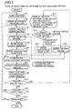
- Fig. 1 is a flowchart showing the flow of the embodiment of the present invention.
- Fig. 2 is a flowchart showing the flow of computation (node analysis method) at step S7 in Fig. 1.
- Databases for various devices include a pipe database, a pipe joint database and a valve database, in which items of data concerning devices to be selected, i.e. pipes, pipe joints and valves (stop valves), have been stored in advance.
- items of data such as ID numbers, names, inner diameters and pipe friction factors are stored.
- Fig. 3 shows a screen of a personal computer. While looking at the screen, the operator selects devices according to the flows shown in Figs. 1 and 2.
- input conditions given by the user are a circuit configuration, lengths of sections, pipe diameters, flow rates at inlet and outlet portions, and a pressure and flow rate at a fluid source.
- a desired value given by the user is a value of allowable pressure loss in each section between the fluid source and an inlet or outlet portion.
- step S1 When the program of the flowchart shown in Fig. 1 is started, initialization is executed at step S1.
- the program (including calculating equations for use in computation) is read, and display of an input screen, connection with the databases for the various devices, etc. are executed.
- node positions arranged in a grid pattern are shown by white squares, and branch positions between the node positions are shown by double lines.
- step S2 a user-specified desired value of allowable pressure loss in each section between the fluid source and an inlet or outlet portion is entered.
- a circuit configuration of the fluid pipeline network is entered.
- branch positions which are shown by the double lines in Fig. 3, are sequentially selected and clicked (when clicked, the double lines become black thick lines).
- Inlet and outlet portions are selected from terminal portions of the circuit (when determined to be an inlet or outlet portion, a node position shown by a white square at a terminal portion changes to a black square).
- a circuit configuration is made by selection of inlet portions, branch points and outlet portions from the node positions and selection of sections to which section devices are to be connected from the branch and node positions.
- branch pipes are used at branch points
- series pipes and pipe joints are used at node positions that form intermediate portions of sections.
- the position of a fluid source is designated next to the upper left-end node position on the left.
- the sections between the inlet portions, branch points and outlet portions selected at step S3 are displayed as branches between the nodes that are shown by black thick lines.
- the length of each section is the sum of the length of pipe, the lengths of pipe joints (including node pipe joints) and the straight pipe-equivalent lengths of valves.
- the length of pipe, the number of pipe joints and the number of valves are entered, and the diameter of pipe, the type of pipe joint and the type of valve are entered by being selected from the databases for the various devices. It should be noted that the diameter and length of pipe and the types and numbers of pipe joints and valves are temporarily selected by taking into account the user's desired input conditions.
- the value of supply pressure of the fluid source is entered (in a pneumatic pipeline network, the fluid source pressure is generally 0.4 to 0.8 MPa; in a coolant pipeline network, it is generally 0.05 to 2 MPa).
- the flow rate value at each of the inlet and outlet portions is entered at step S6.
- the nozzle diameter, the number of nozzles and the opening pressure are entered in place of the flow rate value at each outlet portion on the assumption that a coolant (cooling water) is jetted out from nozzles at the outlet portion.
- a flow rate value is calculated from the nozzle diameter, the number of nozzles and the opening pressure. With this flow rate value, the process is carried out in the same way as in a case where the flow rate value at the outlet portion was entered at step S6.
- the pressure at each node of the fluid pipeline network is obtained by the node analysis method on the basis of the entered parameters.
- the computation using the node analysis method is performed according to the flowchart of Fig. 2.
- calculating equations (1) to (7) shown in Fig. 4 hold (the meaning of each symbol is as shown in Fig. 5), and these equations are stored in advance.
- equation (3) is derived from equations (1) and (2).
- Equation (6) represents the admittance of the pipeline in a case where a gas is used as a fluid.
- Equation (7) represents the admittance of the pipeline in a case where a liquid is used as a fluid.
- an input-output matrix [A in equation (1) in Fig. 4] is made from the entered circuit configuration. It should be noted that, in the input-output matrix, branches and nodes are arranged in rows and columns, respectively, to show whether or not there is a flow at a branch or a node and to indicate the direction of the flow.
- physical data required to calculate the branch diameter and length and the admittance of the fluid pipeline network is read. For the branch diameter, data is selected and read from the pipe database. For the branch length, the user-specified section length is read. The density (varying in value according to the kind of fluid) and the gravitational acceleration are prepared in the program in advance.
- an input-output matrix is made from the entered circuit configuration.
- initial values of the branch flow rate and mean pressure are set for each branch. It should be noted that the initial value of branch flow rate is an appropriate numerical value other than zero, and the mean pressure (the maximum pressure in the circuit) is also an appropriate numerical value (in a pneumatic pipeline network, 1 m 3 /min (ANR) is used as the branch flow rate, and the pneumatic source pressure (MPa) is used as the mean pressure).
- admittance is calculated.
- a gas is used as a fluid (e.g. a pneumatic pipeline network)
- admittance is calculated by using equation (6) in Fig. 4.
- a liquid is used as a fluid (e.g. a coolant pipeline network)
- admittance is calculated by using equation (7) in Fig. 4.
- the node admittance matrix is calculated by using equation (4) in Fig. 4.
- the simultaneous equations (3) are solved to obtain an unknown node pressure and flow rate. It should be noted that the Gaussian elimination previously incorporated in the program is used for this calculation.
- step S7-8 the flow rate at each branch is calculated from the pressure at each node by using equation (5) in Fig. 4.
- step S7-9 it is judged whether or not the difference between the branch flow rate obtained by the calculation at step S7-8 and the branch flow rate initially given at step S7-4 is less than a predetermined value of convergence criterion. If YES is the answer at step S7-9, the process proceeds to step S8 in Fig. 1.
- step S7-9 If it is judged at step S7-9 that the difference between the calculated branch flow rate and the initially given branch flow rate is not less than the value of convergence criterion, a branch flow rate and mean pressure are newly set for each branch at step S7-10. Then, the process proceeds to step S7-5, and the flow of steps S7-5 to S7-9 is repeated.
- the mean pressure set at step S7-10 is obtained by calculating a mean value at each branch from the node pressure obtained by solving the simultaneous equations.
- the results of the computation are outputted.
- the pressure at each branch point in the circuit configuration of the fluid pipeline network is displayed on the lower right of the node position representing the branch point
- the pressure and flow rate at each of the inlet and outlet portions are displayed on the lower right of the node position representing the inlet or outlet portion (the pressure being displayed in the upper place, and the flow rate in the lower place).
- the computational results are printed out and also stored on a hard disk (a magnetic recording medium used with the personal computer), a floppy disk (a magnetic recording medium), an MO (a magneto-optic disk), etc.
- step S10 whether or not to make a change for the better is judged.
- the judgment as to whether or not to make a change for the better is made on the basis of the above-described value of allowable pressure loss. If there is a section that does not satisfy the condition of allowable pressure loss among the sections between the fluid source and the inlet or outlet portions in the fluid pipeline network, it is judged that a change for the better should be made.
- the operator makes the judgment at step S10 while looking at the screen shown in Fig. 3. If it is judged at step S10 that a change for the better should not be made, the process proceeds to step S15.
- a section that does not satisfy the condition of allowable pressure loss among the sections between the fluid source and the inlet or outlet portions in the fluid pipeline network is displayed at step S11.
- an object to be changed for the better i.e. either an inlet/outlet flow rate change or a section device change
- the inlet/outlet flow rate change is chosen. If the operator judges that the section devices should preferably be changed, the section device change is chosen.
- step S12 If the inlet/outlet flow rate change is chosen at step S12, the process proceeds to step S13, at which, in the case of a fluid pipeline network (e.g. a pneumatic pipeline network) other than coolant pipeline networks, a changed value of the flow rate at the inlet or outlet portion as a terminal portion is entered. Then, the process proceeds to step S7.
- a fluid pipeline network e.g. a pneumatic pipeline network
- step S7 In the case of a coolant pipeline network, changed values of the nozzle diameter, the number of nozzles and the opening pressure are entered in place of the flow rate value (the flow executed thereafter is the same as in the case of step S5).
- step S12 If the section device change is chosen at step S12, the process proceeds to step S14, at which changed data items concerning the pipe diameter and length and the types and numbers of pipe joints and valves are entered by being selected from the databases for the various devices. Then, the process proceeds to step S7.
- step S7 The flow from step S7 to step S10 is executed in the same way as in the previous process. The flow from step S10 through steps S11 and S7 to step S10 is repeated until it is judged at step S10 that a change for the better should not be made.
- step S10 If it is judged at step S10 that a change for the better should not be made, whether or not to change the status quo is judged at step S15. If there is no mistake such as a data entry mistake, it is judged that the status quo should not be changed, and the process proceeds to step S16. If it is noticed that there is a data entry mistake or the like, or if it is necessary to read computational results stored on a magnetic recording medium in a previous selection of devices and to change a part of the read results, it is judged at step S15 that the status quo should be changed, and the process returns to step S3.
- step S16 whether or not to terminate the program is judged. If it is judged that the program should be terminated, the process proceeds to "End". If it is desired to make a device selection for another fluid pipeline network, it is judged at step S16 that the program should not be terminated, and the process returns to step S1. By initialization at step S1, the information used for the previous device selection is cleared, and the display of the screen shown in Fig. 3 is also cleared.
- the position of a fluid source is designated next to the upper left-end node position on the left in the circuit configuration shown in Fig. 3, the arrangement may be such that a fluid source is connected to an inlet portion as a terminal portion of the circuit and this inlet portion is regarded as a fluid source.
- the inlet portion also serves as a fluid source, and the pressure at the inlet portion is entered as the fluid source pressure at step S5.
- the desired value given by the user in this case is a value of allowable pressure loss in each section between the inlet portion and an outlet portion.
Landscapes
- Engineering & Computer Science (AREA)
- Mechanical Engineering (AREA)
- General Engineering & Computer Science (AREA)
- Health & Medical Sciences (AREA)
- Public Health (AREA)
- Water Supply & Treatment (AREA)
- Physics & Mathematics (AREA)
- Fluid Mechanics (AREA)
- Pipeline Systems (AREA)
- Management, Administration, Business Operations System, And Electronic Commerce (AREA)
- Information Retrieval, Db Structures And Fs Structures Therefor (AREA)
Abstract
Description
Claims (5)
- A method of selecting devices for use in a fluid pipeline network, comprising the steps of:making a circuit configuration of the fluid pipeline network by connecting together sections between a fluid source, inlet portions, branch points and outlet portions with section devices;giving a pressure at the fluid source and a flow rate at each outlet portion; andadjusting a pressure loss in each section between the fluid source and an inlet or outlet portion to a desired value of allowable pressure loss;
wherein items of data concerning pipes, pipe joints and valves are stored in a pipe database, a pipe joint data base and a valve database, respectively, and calculating equations for use in computation are also stored, and wherein section devices, i.e. pipes, pipe joints and valves, are selected from the pipe database, the pipe joint database and the valve database, respectively, and pressures at the branch points and the outlet portions are computed with respect to the fluid pipeline network for which the section devices have been selected, by using the stored calculating equations. - A method of selecting devices for use in a fluid pipeline network according to claim 1, wherein after entry of the value of allowable pressure loss, the pressure at the fluid source and the flow rate at each of the inlet and outlet portions, all sections of the fluid pipeline network are subjected to computation using a node analysis method to judge whether or not there is a section that does not satisfy a condition of allowable pressure loss, and if there is such a section, an inlet/outlet flow rate change or a section device change is made with respect to said section, and then a judgment as to whether or not there is a section that does not satisfy the condition of allowable pressure loss is made again by computation using the node analysis method, wherein the inlet/outlet flow rate change or the section device change and the computation are repeated until there is no section that does not satisfy the condition of allowable pressure loss.
- A method of selecting devices for use in a fluid pipeline network according to claim 1, wherein node positions and branch positions, which are arranged in a grid pattern, are displayed on a screen, and inlet portions, branch points and outlet portions are selected from the node positions, and further, sections to which section devices are to be connected are selected from the branch positions and the node positions to make a circuit configuration.
- A method of selecting devices for use in a fluid pipeline network according to claim 2, wherein node positions and branch positions, which are arranged in a grid pattern, are displayed on a screen, and inlet portions, branch points and outlet portions are selected from the node positions, and further, sections to which section devices are to be connected are selected from the branch positions and the node positions to make a circuit configuration.
- A method of selecting devices for use in a fluid pipeline network according to claim 2, wherein node positions and branch positions, which are arranged in a grid pattern, are displayed on a screen, and inlet portions, branch points and outlet portions are selected from the node positions, and further, sections to which section devices are to be connected are selected from the branch positions and the node positions to make a circuit configuration, and as a result of the computation using the node analysis method, a pressure is displayed at each branch point, and a pressure and a flow rate are displayed at each of the inlet and outlet portions.
Applications Claiming Priority (2)
| Application Number | Priority Date | Filing Date | Title |
|---|---|---|---|
| JP29224599A JP2001117953A (en) | 1999-10-14 | 1999-10-14 | Fluid pipeline network device selection method and recording medium storing fluid pipeline network device selection program |
| JP29224599 | 1999-10-14 |
Publications (3)
| Publication Number | Publication Date |
|---|---|
| EP1092912A2 true EP1092912A2 (en) | 2001-04-18 |
| EP1092912A3 EP1092912A3 (en) | 2002-11-13 |
| EP1092912B1 EP1092912B1 (en) | 2006-05-17 |
Family
ID=17779340
Family Applications (1)
| Application Number | Title | Priority Date | Filing Date |
|---|---|---|---|
| EP00122563A Expired - Lifetime EP1092912B1 (en) | 1999-10-14 | 2000-10-16 | Method of selecting devices for use in fluid pipeline network |
Country Status (5)
| Country | Link |
|---|---|
| US (1) | US6507792B1 (en) |
| EP (1) | EP1092912B1 (en) |
| JP (1) | JP2001117953A (en) |
| CN (1) | CN1145108C (en) |
| DE (1) | DE60027981T2 (en) |
Cited By (2)
| Publication number | Priority date | Publication date | Assignee | Title |
|---|---|---|---|---|
| EP1813822A4 (en) * | 2004-11-12 | 2012-07-11 | Smc Kk | PNEUMATIC DEVICE SELECTION SYSTEM, PNEUMATIC DEVICE SELECTION METHOD, RECORDING MEDIUM, AND PNEUMATIC DEVICE SELECTION PROGRAM |
| EP4648000A4 (en) * | 2023-02-10 | 2026-03-18 | Mitsubishi Heavy Ind Ltd | SHOPPING ASSISTANCE DEVICE, SHOPPING ASSISTANCE PROCEDURE AND SHOPPING ASSISTANCE PROGRAM |
Families Citing this family (8)
| Publication number | Priority date | Publication date | Assignee | Title |
|---|---|---|---|---|
| US7162399B2 (en) * | 2001-10-05 | 2007-01-09 | Smc Kabushiki Kaisha | System for and method of selecting pneumatic device, and recording medium |
| JP2003316837A (en) * | 2002-04-24 | 2003-11-07 | Rix Corp | Previous evaluation method and system for piping work |
| US8938379B2 (en) * | 2011-07-29 | 2015-01-20 | General Electric Company | Systems, methods, and apparatus for predicting impact on a pipeline delivery infrastructure |
| WO2015124988A1 (en) * | 2014-02-19 | 2015-08-27 | Tata Consultancy Services Limited | Leak localization in water distribution networks |
| GB2564301B (en) * | 2016-03-28 | 2022-01-05 | Nec Corp | Analysis device, analysis method, and program |
| JP7214079B2 (en) * | 2018-06-13 | 2023-01-30 | Smc株式会社 | Fluid circuit selection system and fluid circuit selection method |
| CN112199788B (en) * | 2020-09-28 | 2024-05-24 | 广州广燃设计有限公司 | Design method of buried gas pipeline |
| CN112883662B (en) * | 2021-02-01 | 2024-05-10 | 清华大学 | Dynamic operation hydraulic state estimation method and system for steam heating network |
Family Cites Families (9)
| Publication number | Priority date | Publication date | Assignee | Title |
|---|---|---|---|---|
| US4119391A (en) * | 1974-12-09 | 1978-10-10 | Compressor Controls Corporation | Methods and systems for controlling the operation of means for compressing a fluid medium and the corresponding networks |
| JPS5350863A (en) * | 1976-10-20 | 1978-05-09 | Hitachi Ltd | Demand quantity estimating apparatus for flow rate pressure controlling in piping network |
| US4888706A (en) * | 1982-07-06 | 1989-12-19 | Institute Of Gas Technology | Fluid distribution to multiple users through distributed intelligence sub-centers |
| US5414641A (en) * | 1993-05-11 | 1995-05-09 | Tokyo Gas Co., Ltd | Method and apparatus for determining elementary circuits and initial values of flows in a pipe network |
| JP3543426B2 (en) * | 1995-07-06 | 2004-07-14 | 株式会社日立製作所 | Pipe network management method and system |
| US5940290A (en) * | 1995-12-06 | 1999-08-17 | Honeywell Inc. | Method of predictive maintenance of a process control system having fluid movement |
| FR2745436B1 (en) * | 1996-02-28 | 1998-04-03 | Elf Aquitaine | SELF-CONTAINED ONLINE ELECTRIC POWER GENERATOR |
| TW396254B (en) * | 1997-06-20 | 2000-07-01 | Exxon Production Research Co | Pipeline distribution network systems for transportation of liquefied natural gas |
| JP3542295B2 (en) * | 1998-12-16 | 2004-07-14 | Smc株式会社 | How to select pneumatic components |
-
1999
- 1999-10-14 JP JP29224599A patent/JP2001117953A/en active Pending
-
2000
- 2000-09-07 US US09/656,792 patent/US6507792B1/en not_active Expired - Lifetime
- 2000-10-13 CN CNB001304976A patent/CN1145108C/en not_active Expired - Lifetime
- 2000-10-16 EP EP00122563A patent/EP1092912B1/en not_active Expired - Lifetime
- 2000-10-16 DE DE60027981T patent/DE60027981T2/en not_active Expired - Lifetime
Cited By (2)
| Publication number | Priority date | Publication date | Assignee | Title |
|---|---|---|---|---|
| EP1813822A4 (en) * | 2004-11-12 | 2012-07-11 | Smc Kk | PNEUMATIC DEVICE SELECTION SYSTEM, PNEUMATIC DEVICE SELECTION METHOD, RECORDING MEDIUM, AND PNEUMATIC DEVICE SELECTION PROGRAM |
| EP4648000A4 (en) * | 2023-02-10 | 2026-03-18 | Mitsubishi Heavy Ind Ltd | SHOPPING ASSISTANCE DEVICE, SHOPPING ASSISTANCE PROCEDURE AND SHOPPING ASSISTANCE PROGRAM |
Also Published As
| Publication number | Publication date |
|---|---|
| DE60027981T2 (en) | 2006-09-21 |
| EP1092912B1 (en) | 2006-05-17 |
| CN1145108C (en) | 2004-04-07 |
| DE60027981D1 (en) | 2006-06-22 |
| EP1092912A3 (en) | 2002-11-13 |
| CN1293332A (en) | 2001-05-02 |
| US6507792B1 (en) | 2003-01-14 |
| JP2001117953A (en) | 2001-04-27 |
Similar Documents
| Publication | Publication Date | Title |
|---|---|---|
| EP1092912B1 (en) | Method of selecting devices for use in fluid pipeline network | |
| US5706453A (en) | Intelligent real-time graphic-object to database linking-actuator for enabling intuitive on-screen changes and control of system configuration | |
| Rothfarb et al. | Optimal design of offshore natural-gas pipeline systems | |
| Nasirian et al. | Leakage detection in water distribution network based on a new heuristic genetic algorithm model | |
| CN111396985A (en) | A kind of central heating pipe network static hydraulic balance automatic adjustment system and realization method | |
| US6704696B1 (en) | Apparatus for and method of designing fluid control devices | |
| CN115167151B (en) | A method, device and system for grid-connected joint gas supply of compressor units based on dynamic simulation and intelligent control strategy | |
| Boulos et al. | An explicit algorithm for calculating operating parameters for water networks | |
| JP2002372200A (en) | Pipe network analysis pipe network data creation method, pipe network analysis pipe network data creation apparatus, and pipe network analysis pipe network data creation program | |
| JP2886022B2 (en) | Pipe network analysis data generation method | |
| CN110390170A (en) | A kind of gas ductwork connection inspection method and pipe network online editing system | |
| CN116186951A (en) | Method and device for checking connection relation of three-dimensional pipeline model | |
| JP2006244072A (en) | Plant state simulation method and system | |
| CN120105762B (en) | A BIM-based hydraulic analysis method for pipelines in hydropower station buildings | |
| JP2006163451A (en) | Conduit network analysis method and system | |
| JPS6267667A (en) | Data input device for conduit network diagram | |
| JPH07182306A (en) | Flow rate / pressure simulation device for piping | |
| CN109902846A (en) | A kind of simplified method and system of water supply network | |
| JP4361302B2 (en) | Cooling water piping design equipment | |
| CN107851133B (en) | Method, system, and medium for geometric transformation of objects in an object-oriented environment | |
| CN120316941A (en) | A method for locating congestion and optimizing capacity expansion in complex natural gas pipeline networks | |
| JPH08200890A (en) | Expander for heat pump refrigeration cycle | |
| CN117421846A (en) | Automatic calculation method for equipment relationship, electronic equipment and medium | |
| JP2731041B2 (en) | Hydraulic analyzer | |
| CN117972948A (en) | An intelligent optimization design system for ship pipeline resistance based on CATIA software platform |
Legal Events
| Date | Code | Title | Description |
|---|---|---|---|
| PUAI | Public reference made under article 153(3) epc to a published international application that has entered the european phase |
Free format text: ORIGINAL CODE: 0009012 |
|
| 17P | Request for examination filed |
Effective date: 20001016 |
|
| AK | Designated contracting states |
Kind code of ref document: A2 Designated state(s): AT BE CH CY DE DK ES FI FR GB GR IE IT LI LU MC NL PT SE |
|
| AX | Request for extension of the european patent |
Free format text: AL;LT;LV;MK;RO;SI |
|
| PUAL | Search report despatched |
Free format text: ORIGINAL CODE: 0009013 |
|
| AK | Designated contracting states |
Kind code of ref document: A3 Designated state(s): AT BE CH CY DE DK ES FI FR GB GR IE IT LI LU MC NL PT SE |
|
| AX | Request for extension of the european patent |
Free format text: AL;LT;LV;MK;RO;SI |
|
| AKX | Designation fees paid |
Designated state(s): DE FR GB IT |
|
| 17Q | First examination report despatched |
Effective date: 20040329 |
|
| GRAP | Despatch of communication of intention to grant a patent |
Free format text: ORIGINAL CODE: EPIDOSNIGR1 |
|
| GRAS | Grant fee paid |
Free format text: ORIGINAL CODE: EPIDOSNIGR3 |
|
| GRAA | (expected) grant |
Free format text: ORIGINAL CODE: 0009210 |
|
| AK | Designated contracting states |
Kind code of ref document: B1 Designated state(s): DE FR GB IT |
|
| PG25 | Lapsed in a contracting state [announced via postgrant information from national office to epo] |
Ref country code: IT Free format text: LAPSE BECAUSE OF FAILURE TO SUBMIT A TRANSLATION OF THE DESCRIPTION OR TO PAY THE FEE WITHIN THE PRESCRIBED TIME-LIMIT;WARNING: LAPSES OF ITALIAN PATENTS WITH EFFECTIVE DATE BEFORE 2007 MAY HAVE OCCURRED AT ANY TIME BEFORE 2007. THE CORRECT EFFECTIVE DATE MAY BE DIFFERENT FROM THE ONE RECORDED. Effective date: 20060517 |
|
| REG | Reference to a national code |
Ref country code: GB Ref legal event code: FG4D |
|
| REF | Corresponds to: |
Ref document number: 60027981 Country of ref document: DE Date of ref document: 20060622 Kind code of ref document: P |
|
| ET | Fr: translation filed | ||
| PLBE | No opposition filed within time limit |
Free format text: ORIGINAL CODE: 0009261 |
|
| STAA | Information on the status of an ep patent application or granted ep patent |
Free format text: STATUS: NO OPPOSITION FILED WITHIN TIME LIMIT |
|
| 26N | No opposition filed |
Effective date: 20070220 |
|
| REG | Reference to a national code |
Ref country code: FR Ref legal event code: PLFP Year of fee payment: 16 |
|
| REG | Reference to a national code |
Ref country code: FR Ref legal event code: PLFP Year of fee payment: 17 |
|
| REG | Reference to a national code |
Ref country code: FR Ref legal event code: PLFP Year of fee payment: 18 |
|
| REG | Reference to a national code |
Ref country code: FR Ref legal event code: PLFP Year of fee payment: 19 |
|
| PGFP | Annual fee paid to national office [announced via postgrant information from national office to epo] |
Ref country code: DE Payment date: 20191021 Year of fee payment: 20 |
|
| PGFP | Annual fee paid to national office [announced via postgrant information from national office to epo] |
Ref country code: IT Payment date: 20191028 Year of fee payment: 20 Ref country code: FR Payment date: 20191028 Year of fee payment: 20 |
|
| PGFP | Annual fee paid to national office [announced via postgrant information from national office to epo] |
Ref country code: GB Payment date: 20191021 Year of fee payment: 20 |
|
| REG | Reference to a national code |
Ref country code: DE Ref legal event code: R071 Ref document number: 60027981 Country of ref document: DE |
|
| REG | Reference to a national code |
Ref country code: GB Ref legal event code: PE20 Expiry date: 20201015 |
|
| PG25 | Lapsed in a contracting state [announced via postgrant information from national office to epo] |
Ref country code: GB Free format text: LAPSE BECAUSE OF EXPIRATION OF PROTECTION Effective date: 20201015 |