EP1092665A2 - Ribbon winding preventing device and method and traverse drum - Google Patents
Ribbon winding preventing device and method and traverse drum Download PDFInfo
- Publication number
- EP1092665A2 EP1092665A2 EP00122094A EP00122094A EP1092665A2 EP 1092665 A2 EP1092665 A2 EP 1092665A2 EP 00122094 A EP00122094 A EP 00122094A EP 00122094 A EP00122094 A EP 00122094A EP 1092665 A2 EP1092665 A2 EP 1092665A2
- Authority
- EP
- European Patent Office
- Prior art keywords
- traverse
- winding
- yarn
- drum
- package
- Prior art date
- Legal status (The legal status is an assumption and is not a legal conclusion. Google has not performed a legal analysis and makes no representation as to the accuracy of the status listed.)
- Withdrawn
Links
Images




Classifications
-
- B—PERFORMING OPERATIONS; TRANSPORTING
- B65—CONVEYING; PACKING; STORING; HANDLING THIN OR FILAMENTARY MATERIAL
- B65H—HANDLING THIN OR FILAMENTARY MATERIAL, e.g. SHEETS, WEBS, CABLES
- B65H54/00—Winding, coiling, or depositing filamentary material
- B65H54/02—Winding and traversing material on to reels, bobbins, tubes, or like package cores or formers
- B65H54/38—Arrangements for preventing ribbon winding ; Arrangements for preventing irregular edge forming, e.g. edge raising or yarn falling from the edge
-
- B—PERFORMING OPERATIONS; TRANSPORTING
- B65—CONVEYING; PACKING; STORING; HANDLING THIN OR FILAMENTARY MATERIAL
- B65H—HANDLING THIN OR FILAMENTARY MATERIAL, e.g. SHEETS, WEBS, CABLES
- B65H54/00—Winding, coiling, or depositing filamentary material
- B65H54/02—Winding and traversing material on to reels, bobbins, tubes, or like package cores or formers
- B65H54/40—Arrangements for rotating packages
- B65H54/46—Package drive drums
- B65H54/48—Grooved drums
-
- B—PERFORMING OPERATIONS; TRANSPORTING
- B65—CONVEYING; PACKING; STORING; HANDLING THIN OR FILAMENTARY MATERIAL
- B65H—HANDLING THIN OR FILAMENTARY MATERIAL, e.g. SHEETS, WEBS, CABLES
- B65H2701/00—Handled material; Storage means
- B65H2701/30—Handled filamentary material
- B65H2701/31—Textiles threads or artificial strands of filaments
Definitions
- the present invention relates to the configuration of a winding device in an automatic winder, a double twister, a false twister, or the like and the configuration of a traverse drum for use in the winding device, and in particular, to a technique for preventing ribbon winding during production of winding packages to improve yarn quality.
- automatic winders which comprise a traverse drum having a traverse groove formed in its peripheral surface and through which a yarn unwound from a spinning bobbin or the like is traversed to produce a winding package rotationally driven by the traverse drum in contact therewith.
- Double twisters and false twisters are also known which comprise a traverse drum having a traverse groove formed therein to traverse a yarn.
- the yarn traversed through the traverse groove is sequentially wound around the winding package, its package diameter increases gradually.
- the ribbon winding occurs on the winding package.
- the ribbon winding is a phenomenon in which the yarn wound on the winding package passes through substantially the same yarn path during a certain period, so that an extremely small number of intersections of the yarn are formed on the package.
- a winding package in which the ribbon winding has occurred may cause sluffing or yarn breakage by entanglement of yarn (a process called "latching") during a postprocess when the yarn is unwound.
- Many methods for preventing ribbon winding on the winding package have been provided, including periodic braking of the drum or the package.
- a method is thus well known which forms a shortened passage in part of the traverse groove formed in the traverse drum to change the winding value (number of winding) in order to enable two winding values for the traverse drum to be switched.
- This conventional configuration requires the two winding values to be switched during a winding operation of an automatic winder or the like. For example, in a traverse drum with 2 winding values (2W) and 3 winding values (3W), the winding values is alternately changed for each traverse operation. Accordingly, complicated control is required and the yarn path must frequently be changed. Therefore, this method is not efficient.
- the traverse drum has a plurality of continuous traverse grooves for different winding values formed therein.
- the present invention has means for switching a yarn path to determine which of the plurality of continuous traverse grooves for different winding values is used to traverse the yarn.
- means for detecting a diameter of the package at which the ribbon winding occurs is provided to provide such control that the winding value for the traverse drum is changed near a diameter at which ribbon winding has occurred.
- the traverse drum has a plurality of continuous traverse grooves formed therein and having different winding values.
- the plurality of continuous traverse grooves are formed substantially completely independently.
- a continuous traverse groove for 2 winding values and a continuous traverse groove for 2.5 winding values are formed.
- a half or more of the plurality of continuous traverse grooves are independently formed and the remaining traverse grooves constitute a common passage.
- a forward and backward portions of at least one continuous traverse groove have different winding values.
- An automatic winder 1 is a device for rewinding a yarn from a spinning bobbin 2 produced by a ring spinning machine or the like, into a package 3.
- the spinning bobbin 2 is conveyed on a machine base (not shown in the drawings) and placed at a predetermined position of the automatic winder 1. A yarn end on the spinning bobbin 1 is captured and a yarn Y is transferred upward. The yarn Y is tensed by a tension device 4, passed through a yarn defect detecting head 5, traversed by a traverse drum 6, and then wound into the package 3.
- a splicer 7 is disposed on a yarn path leading from the yarn defect detecting head 5 to the traverse drum 6, to join the yarn after removal of a yarn defect if the defect has been found in the yarn Y or to join the yarn for a new spinning bobbin 2 that has replaced an empty bobbin. This allows several to several tens of spinning bobbins 2 to be wound into knot-less high quality packages 3.
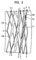
- the traverse drum 6 has a continuous traverse groove 11 formed in a drum surface.
- the traverse groove 11 comprises a traverse forward passage 11F for transferring the yarn leftward in Figure 1 and a traverse backward passage 11B for transferring the yarn rightward so that the yarn Y is traversed leftward through the traverse forward passage 11F and then rightward through the traverse backward passage 11B before returning to the original position.
- the yarn Y is sequentially traversed through the traverse groove 11 in this manner and then wound into the package 3 driven by the traverse drum 6 in surface contact therewith.
- the traverse drum 6 has two different types of traverse grooves 11 for different winding values (hereafter referred to as "W" as appropriate) formed therein to prevent ribbon winding as described above.
- traverse groove 11 for a normal operation adapted to have the traverse forward passage 11F and the traverse backward passage 11B both for 2.5W.
- the other is the traverse groove 11 for a ribbon winding diameter operation having 3W for the traverse forward passage 11F and 2.5W for the traverse backward passage 11B, and an average drum winding value constituted by two traverse (two forward and backward operations) is 2.75W .
- the yarn Y passes through the traverse groove 11 as the traverse drum 6 rotates, that is, it moves from the point (a) through a branching portion SP and a groove L1 to a point (b).
- the yarn Y then moves from the point (b) to a point (c) and then from the point (c) to a point (d) to reach a right end of the traverse drum 6. That is, the traverse groove 11 joining the points (a), (b), (c), (d) constitutes the traverse forward passage 11F. Since the leftward movement of the yarn Y causes the traverse drum 6 to be rotated 2.5 times, a drum winding value for the traverse forward passage 11F is 2.5W.
- the yarn Y further passes through the traverse guide 11 as the traverse drum 6 rotates, in this case, it moves from the point (d) to a point (e), then from the point (e) to a point (f), and then from the point (f) to the point (a) to reach the right end of the traverse drum 6. That is, the traverse groove 11 joining the points (d), (e), (f), (a) constitutes the traverse backward passage 11B. Since the rightward movement of the yarn Y causes the traverse drum 6 to be rotated 2.5 times, a drum winding value for the traverse backward passage 11B is 2.5W.
- the traverse drum 6 has formed therein the traverse groove with the forward passage for 2.5W and the backward passage for 2.5W.
- the yarn Y passes through the traverse groove 11 as the traverse drum 6 rotates, that is, it moves from the point (a) through a branching portion SP and a groove L2 to a point (g).
- the yarn Y then moves from the point (g) to a point (h) and then from the point (h) to a point (i) to reach a left end of the traverse drum 6. That is, the traverse groove 11 joining the points (a), (g), (h), (i) constitutes the traverse forward passage 11F. Since the leftward movement of the yarn Y causes the traverse drum 6 to be rotated 3 times, a drum winding value for the traverse forward passage 11F is 3W.
- the yarn Y further passes through the traverse guide 11 as the traverse drum 6 rotates, in this case, it moves from the point (i) to a point (j), then from the point (j) to a point (k), and then from the point (k) to the point (m) to reach a right end of the traverse drum 6. That is, the traverse groove 11 joining the points (i), (j), (k), (m) constitutes the traverse backward passage 11B. Since the rightward movement of the yarn Y causes the traverse drum 6 to be rotated 2.5 times, a drum winding value for the traverse backward passage 11B is 2.5W. The yarn Y has thus performed one traverse (forward and backward operation), but further performs the second traverse operation without returning to the point (a).
- the yarn Y is traversed leftward again from the point (m) and reaches a point (n), it then moves from the point (n) to a point (b), then from the point (b) to a point (c), and then from the point (c) to a point (d) to reach the left end of the traverse drum 6.
- the yarn Y is further traversed rightward from the point (d) to move through the traverse backward passage 11B for 2.5W composed of the points (d), (e), (f), (a) to reach the right end of the traverse drum before returning to the starting point (a).
- the traverse drum 6 has formed therein the traverse groove 11 for two forward-and-backward operations comprising the forward passage for 3W, the backward passage for 2.5W, the forward passage for 3W, and the backward passage for 2.5W.
- the traverse drum 6 has the plurality of (in this embodiment, two types of) continuous traverse grooves 11 for different drum winding values formed therein.
- the two continuous traverse grooves 11 for different winding values are not completely mutually independent, but half or more (most) of the traverse grooves 11 are mutually independent, while the remaining portions (a part) thereof constitute a common path.
- the pin cylinder 24 is configured so as to be turned on and off and when turned on, projects to a position A in Figure 1 to bend the yarn Y (the thus formed yarn path is denoted by Y1 in Figure 1). This causes the yarn Y to be guided toward the groove L1 for the normal operation with the forward and backward operations both for 2.5W.
- the pin cylinder 24 is withdrawn to release the tension exerted on the yarn Y (the thus formed yarn path is denoted by Y2 in Figure 1).
- the yarn Y is then guided toward the groove L2 for the ribbon winding operation with an average winding value of 2.5W.
- the yarn Y is sequentially wound into the winding package 3 through the traverse groove 11 for the above described normal operation.
- Figure 4 shows the relationship between the package diameter R and the winding value of the ribbon winding. As shown in this figure, there are many ribbon winding packages such as those for 2W, 3W, . . . , but ribbon winding packages for 1W and 1.5W are particularly affected.
- Figure 5A shows ribbon winding with 1W
- Figure 5B shows ribbon winding with 1.5W
- the ribbon winding with 1W causes the yarn wound on the package to form only one yarn intersection thereon
- the ribbon winding with 1.5W causes the yarn to form only two yarn intersections thereon. Consequently, the yarn is free between one intersection and the next yarn intersection, so that sluffing is likely to occur during fast unwinding.
- the above described traverse groove 11 for the ribbon winding operation is used to shift the yarn path for the yarn wound on the package to prevent ribbon winding.
- this embodiment is configured to prevent ribbon winding with 1W and 1.5W
- configurations can be similarly provided for preventing ribbon winding with 0.75W, 1.25W, 1.75W, or 2W.
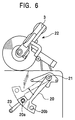
- Figure 6 shows the configuration of the means for detecting a diameter of a package at which ribbon winding may occur.
- a sensor lever 20 can rotationally move around a shaft 21, and a cradle 22 for supporting the winding package 3 operates in conjunction with the sensor lever 20 and moves around the shaft 21 integrally therewith.
- the sensor lever 21 has ribbon winding diameter detecting holes 20a, 20b drilled at ends thereof and a proximity switch 23 disposed at a position lapping with a trajectory of the detecting holes 20a, 20b which is formed as the sensor lever 20 moves rotationally.
- the proximity switch 23 is initially turned on and is turned off while the detecting hole 20a are passing by.
- the cradle 22 moves rotationally, and once the package diameter R reaches the value of a ribbon winding diameter for 1.5W, the detecting hole 20a passes over the proximity switch 23, which is then turned on.
- the pin cylinder 24 is then turned off to feed the yarn Y from the separating portion SP to the groove L2, so that the yarn Y is traversed through the traverse groove 11 for the ribbon winding operation.
- the pin cylinder 24 is turned on again to return the operation to the normal one for a drum winding value of 2.5W.
- a graph F1 shows the relationship between the package diameter R for a drum winding value of 2.5W and the package winding value W
- a graph F2 shows the relationship between the package diameter R for a drum winding value of 2.75W and the package winding value W.
- the 2.5W operation is normally performed and the traverse drum is switched to the 2.75W operation when the package diameter is close to R1 at where the 1.5W ribbon winding may occur. That is, the portions shown by the solid line on the graphs F1 and F2 indicate actual winding values for the traverse drum, indicating that the operation is switched to the 2.75W one only between a point (x1) and a point (x2) on the graph F1.
- the detecting hole 20b turns on the proximity switch 23 to switch to the ribbon winding operation.
- the operation returns to the normal one.
- the winding value for the traverse drum 6 is switched to 2.75W when the package diameter is closed to R2 at which the 1W ribbon winding may occur (between a point (x3) and a point (x4)).
- the winding value for the traverse drum 6 is switched from 2.5W to 2.75W to shift the yarn path on the package to prevent ribbon winding.
- the present invention provides a configuration for using the traverse groove 11 to traverse and wind the yarn into the package 3, wherein the traverse drum 6 has the plurality of continuous traverse grooves 11 for different winding values formed therein and wherein the pin cylinder 24 acting as the means for switching the yarn path is provided to determine which of the plurality of continuous traverse grooves 11 is used to traverse the yarn. Consequently, the pin cylinder 24 can be turned on and off to change the winding value for the traverse drum 6, which is winding the yarn into the package.
- the windng value since the means for detecting the ribbon winding occurring diameter which is composed of the sensor lever 20, the proximity switch 23, and other components is provided to change the winding value for the traverse drum 6 when the package diameter is close to the ribbon winding diameter, the windng value must be switched only when the package diameter is close to the ribbon winding diameter, thereby simplifying control to stabilize the winding operation. That is, if control is provided such that the winding value is constantly changed during the winding operation (regardless of whether or not the package diameter is close to the ribbon winding diameter) as in the prior art, complicated control is required and the yarn is not stably fed because the yarn path is frequently switched.
- the present invention can prevent ribbon winding with the minimum required switching operation, thereby providing an efficient configuration.
- Figure 7 is a graph comparing a standard drum and the traverse drum according to the present invention in terms of performance.
- the standard drum has a constant drum winding value.
- Figures 7A and 7B are graphs representing the tension of the yarn observed when it is unwound at a high speed (for example, 1,600 m/min.) near a 1W ribbon winding layer;
- Figure 7A shows a package obtained by the standard drum, while
- Figure 7B shows a package obtained by the traverse drum 6 according to the present invention.
- the yarn is wound at a drum winding value of 2.5W during the normal operation, whereas it is wound at a drum winding value of 2.75W during the winding operation at a certain package diameter which the ribbon winding occurs, but conversely, the normal operation may be based on 2.75W, which is then switched to 2.5W for the winding operation at a certain package diameter which the ribbon winding occurs.
- the normal operation may be based on 2.75W, which is then switched to 2.5W for the winding operation at a certain package diameter which the ribbon winding occurs. The latter case provides similar effects.
- the traverse drum 6 has the traverse groove 11 for the average 2.75W in addition to the traverse groove 11 based on 2.5W, but it may have a traverse groove for 3W in addition to a traverse groove based on 2W (2W x 2W forward and backward operations) so that the yarn is wound at a drum winding value of 2W during the normal operation whereas it is wound with a switching operation 3W-2W-3W-2W... (that is, an average drum winding value of 2.5W) during the ribbon winding operation, thereby preventing ribbon winding.
- a traverse drum may be configured which has a traverse groove with a forward and backward paths both for 2.5W and a traverse groove with a forward and backward paths both for 2.0W.
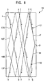
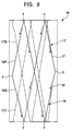
- a traverse drum 16 shown in Figures 8 and 9 comprises a first traverse groove 17 having a first traverse forward path 17F and a first traverse backward path 17B both configured for 2.5W and a second traverse groove 18 having a second traverse forward path 18F and a second traverse backward path 18B both configured for 2.0W.
- the two continuous traverse grooves 17, 18 for different winding values are formed completely independently.
- the yarn Y passes through the first traverse groove 17 as the traverse drum 16 rotates, that is, it moves from the point (p) through a separating point (sp) to a point (q).
- the yarn Y then moves from the point (q) to a point (r), then from the point (r) to a point (s), and then from the point (s) to a point (t) to reach a left end of the traverse drum 16.
- the first traverse groove 17 joining the point (p) and point (t) through the separating point (sp) and the points (q), (r), (s) constitutes the traverse forward path 17F. Since the leftward movement of the yarn Y from the point (p) to the point (t) causes the traverse drum 16 to be rotated 2.5 times, a drum winding value for the traverse forward path 17F is 2.5W.
- the yarn Y further passes through the first traverse groove 17 as the traverse drum 16 rotates, in this case, it moves from the point (t) to a point (u), then from the point (u) to a point (v), and then from the point (v) to the point (p) through the confluence (cf) to reach the right end of the traverse drum 16. That is, the first traverse groove 17 joining the points (t), (u), (v), (cf), (p) constitutes the traverse backward path 17B. Since the rightward movement of the yarn Y causes the traverse drum 16 to be rotated 2.5 times, a drum winding value for the traverse backward path 17B is 2.5W.
- the traverse forward path 17F of the first traverse groove 17 is adapted for 2.5W, while the traverse backward path 17B of the first traverse groove 17 is adapted for 2.5W.
- the yarn Y passes through the second traverse groove 18 as the traverse drum 16 rotates, that is, it moves from the point (p) through the separating portion (sp) to a point (x) shown at the lower end.
- the yarn Y then moves from a point (x) shown at the upper end to a point (y) shown at the lower end and then from a point (y) shown at the upper end to a point (z) to reach a left end of the traverse drum 16.
- the second traverse groove 18 joining the points (p) and (z) through the separating point (sp) and the points (x), (y) constitutes the traverse forward path 18F. Since the leftward movement of the yarn Y from the point (p) to the point (z) causes the traverse drum 16 to be rotated twice, a drum winding value for the traverse forward path 18F is 2.0W.
- the yarn Y further passes through the second traverse groove 18 as the traverse drum 16 rotates, in this case, it moves from the point (z) to the point (y) shown at the lower end, then from the point (y) shown at the upper end to the point (x) shown at the lower end, and then from the point (x) shown at the upper end to the point (p) through the confluence (cf) to reach the right end of the traverse drum 16. That is, the second traverse groove 18 joining the points (z), (y), (x), (cf), (p) constitutes the traverse forward path 18B. Since the rightward movement of the yarn Y causes the traverse drum 16 to be rotated twice, a drum winding value for the traverse backward path 18B is 2.0W.
- the traverse forward path 18F of the second traverse groove 18 is adapted for 2.0W, while the traverse backward path 18B of the second traverse groove 18 is adapted for 2.0W.
- the first traverse groove 17 and the second traverse groove 18 in the taverse drum 16 do not substantially have a common path and are formed as substantially perfectly independent paths.
- the traverse drum 16 has the plurality of (in this embodiment, two types of) independent traverse grooves, that is, the first traverse groove 17 and the second traverse groove 18, which have different winding values.
- the traverse drum 16 allows the path through which the yarn Y is traversed to be switched at the separating point (sp) to the first traverse groove 17 or the second traverse groove 18.
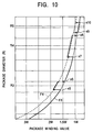
- Figure 10 shows the relationship between the package diameter R and the winding value W of the ribbon winding for the traverse drum 16.
- a graph F3 shows the relationship between the package diameter R and the package winding value W with the second traverse groove 18 for 2.0W
- a graph F4 shows the relationship between the package diameter R and the package winding value W with the first traverse groove 17 for 2.5W.
- the winding value is switched to 2.5W when the package diameter is close to R3 at which the 1.5W ribbon winding may occur (between points (x5) and (x6)) and when the package diameter is close to R4 at which the 1W ribbon winding may occur (between points (x7) and (x8)), while 2.0W is used in the other areas, as shown in the graph F3, thereby preventing ribbon winding.
- the wining value is switched to 2.0W when the package diameter is close to R5 at which the 1W ribbon winding may occur (between points (x9) and (x10)), while 2.5W is used in the other areas, as shown in the graph F4, thereby preventing ribbon winding.
- the present traverse drum 16 enables both winding mainly using 2.0W and winding mainly using 2.5W.
- the one type of traverse drum 16 can wind the yarn using the plurality of winding values while preventing ribbon winding. As a result, the traverse drum 16 can be generalized.
- a package into which the yarn has been wound at 2.0W has a smaller winding density, so that the yarn Y can be dyed while in the form of the package, thereby enabling faster unwinding than in the case of 2.5W or 2.75W.
- the traverse drum has a plurality of continuous traverse grooves for different winding values formed therein. Consequently, the winding value for the traverse drum can be selected from a range of values.
- Means for switching a yarn guide is provided to determine which of the plurality of continuous traverse grooves for different winding values is used to traverse the yarn. As a result, the winding value for the traverse drum can be changed during a winding operation by an automatic winder or the like.
- means for detecting a package diameter at which ribbon winding may occur is provided to effect such control that the winding value for the traverse drum is changed when a package diameter is close to the ribbon winding diameter. Consequently, the winding value must be switched only when the package diameter is close to the ribbon winding diameter, thereby simplifying control to stabilize the winding operation. Additionally, ribbon winding is prevented with the minimum required switching operation, thereby providing an efficient configuration.
- the traverse drum has a plurality of continuous traverse grooves formed therein and having different winding values. Accordingly, the one type of traverse drum can wind the yarn using different winding values and can wind the yarn using a plurality of winding values while preventing ribbon winding. As a result, the traverse drum can be generalized.
- the plurality of continuous traverse grooves are formed substantially completely independently. Consequently, the plurality of continuous traverse grooves has no common path to allow the single drum to wind the yarn at substantially completely different winding values.
- a continuous traverse groove for 2 winding values and a continuous traverse groove for 2.5 winding values are formed.
- the traverse drum can be used for dyeing winding and can be generalized.
- Half or more of the plurality of continuous traverse grooves are independently formed and a remaining part of the traverse grooves constitutes a common path. Consequently, the amount of traverse grooves can be reduced to facilitate manufacturing of the traverse drum.
- a forward and backward portions of at least one continuous traverse groove have different winding values. As a result, ribbon winding can be more effectively prevented.
Landscapes
- Engineering & Computer Science (AREA)
- Textile Engineering (AREA)
- Winding Filamentary Materials (AREA)
Abstract
Description
Claims (8)
- A ribbon winding preventing device operative in a configuration for using a traverse groove formed in a traverse drum to traverse and wind a yarn into a package, the device being characterized in that the traverse drum has a plurality of continuous traverse grooves for different winding values formed therein.
- A ribbon winding preventing device according to Claim 1 characterized by having means for switching a yarn path to determine which of the plurality of continuous traverse grooves for different winding values is used to traverse the yarn.
- A ribbon winding preventing method operative in a configuration for using a traverse groove formed in a traverse drum to traverse and wind a yarn into a package, the device being characterized in that means for detecting a package diameter at which ribbon winding may occur is provided to effect such control that the winding value for the traverse drum is changed when a package diameter is close to the ribbon winding diameter.
- A traverse drum characterized by having a plurality of continuous traverse grooves formed therein and having different winding values.
- A traverse drum according to Claim 4 characterized in that the plurality of continuous traverse grooves are formed substantially completely independently.
- A traverse drum according to Claim 4 or Claim 5 characterized in that a continuous traverse groove for 2 winding values and a continuous traverse groove for 2.5 winding values are formed.
- A traverse drum according to Claim 4 characterized in that half or more of the plurality of continuous traverse grooves are independently formed and a remaining part of the traverse grooves constitutes a common path.
- A traverse drum according to any one of Claims 4 to 7 characterized in that a forward and backward portions of at least one continuous traverse groove have different winding values.
Applications Claiming Priority (4)
| Application Number | Priority Date | Filing Date | Title |
|---|---|---|---|
| JP29397999 | 1999-10-15 | ||
| JP29397999 | 1999-10-15 | ||
| JP2000251051 | 2000-08-22 | ||
| JP2000251051A JP3696778B2 (en) | 1999-10-15 | 2000-08-22 | Traverse drum |
Publications (2)
| Publication Number | Publication Date |
|---|---|
| EP1092665A2 true EP1092665A2 (en) | 2001-04-18 |
| EP1092665A3 EP1092665A3 (en) | 2002-04-03 |
Family
ID=26559635
Family Applications (1)
| Application Number | Title | Priority Date | Filing Date |
|---|---|---|---|
| EP00122094A Withdrawn EP1092665A3 (en) | 1999-10-15 | 2000-10-11 | Ribbon winding preventing device and method and traverse drum |
Country Status (3)
| Country | Link |
|---|---|
| US (1) | US6425546B1 (en) |
| EP (1) | EP1092665A3 (en) |
| JP (1) | JP3696778B2 (en) |
Cited By (1)
| Publication number | Priority date | Publication date | Assignee | Title |
|---|---|---|---|---|
| DE102005054356A1 (en) * | 2005-11-15 | 2007-05-16 | Saurer Gmbh & Co Kg | Method for avoiding image windings |
Family Cites Families (5)
| Publication number | Priority date | Publication date | Assignee | Title |
|---|---|---|---|---|
| US3690579A (en) * | 1971-11-15 | 1972-09-12 | Northrop Carolina Inc | Textile thread winder with improved thread traversing mechanism |
| JPS61145075A (en) * | 1984-12-19 | 1986-07-02 | Murata Mach Ltd | Method and device for thread winding |
| JPH06615B2 (en) * | 1988-07-27 | 1994-01-05 | 村田機械株式会社 | Thread winding method and device |
| JPH0346966A (en) * | 1989-07-14 | 1991-02-28 | Murata Mach Ltd | Package take-up method |
| DE19607905B4 (en) * | 1996-03-01 | 2006-09-14 | Saurer Gmbh & Co. Kg | Method and device for producing cheeses in wild winding |
-
2000
- 2000-08-22 JP JP2000251051A patent/JP3696778B2/en not_active Expired - Fee Related
- 2000-10-11 EP EP00122094A patent/EP1092665A3/en not_active Withdrawn
- 2000-10-13 US US09/689,586 patent/US6425546B1/en not_active Expired - Fee Related
Cited By (1)
| Publication number | Priority date | Publication date | Assignee | Title |
|---|---|---|---|---|
| DE102005054356A1 (en) * | 2005-11-15 | 2007-05-16 | Saurer Gmbh & Co Kg | Method for avoiding image windings |
Also Published As
| Publication number | Publication date |
|---|---|
| JP3696778B2 (en) | 2005-09-21 |
| EP1092665A3 (en) | 2002-04-03 |
| US6425546B1 (en) | 2002-07-30 |
| JP2001180868A (en) | 2001-07-03 |
Similar Documents
| Publication | Publication Date | Title |
|---|---|---|
| JP5287992B2 (en) | Yarn winding device | |
| CN101837909B (en) | Method and device for operating station of textile machine for manufacturing cross-wound spools and station for executing the method | |
| US3075715A (en) | Process for forming thread reserve windings | |
| US3251560A (en) | Winding machine | |
| JPS6013941B2 (en) | Method for preventing abnormal yarn splicing in a yarn winding machine | |
| US4433534A (en) | Apparatus for splicing spun yarns | |
| US6629660B1 (en) | Take-up method and device for synthetic fiber and method of using thread package | |
| US3920193A (en) | Winding apparatus with automatic changing of tubes or the like | |
| US6053450A (en) | Machine and method of forming yarn package | |
| US6425546B1 (en) | Ribbon winding preventing method and traverse drum | |
| CZ300398B6 (en) | Method for producing graduated precision windings | |
| CN115676509A (en) | Method for operating a station of a yarn winding machine and a yarn winding machine | |
| EP2078690A2 (en) | Traverse drum and yarn winding device using the same | |
| EP3640173B1 (en) | Yarn-winding device | |
| EP1127833A2 (en) | Automatic winder | |
| ITMI950647A1 (en) | PROCESS FOR JOINING TEXTILE THREADS TO RESTORE THEIR CONTINUITY IN A WINDING UNIT | |
| JPH07125920A (en) | Yarn winding method | |
| EP1129976B1 (en) | Elastic-yarn package and method of operating a take-up winder for elastic yarn | |
| JPH08282916A (en) | Large package of yarn for knitting loom and winder for producing the same | |
| EP1506933A1 (en) | Ribbon winding preventing method and apparatus | |
| JP7848466B2 (en) | Method and apparatus for preparing spinning cups | |
| CN115676499A (en) | Method for operating a workstation of a textile machine and a workstation of a textile machine | |
| JP2007290839A (en) | Control device for winding ended yarn | |
| JP3385754B2 (en) | Thread switching method of revolving yarn winding machine | |
| JP2001354361A (en) | Thread winding method and thread package |
Legal Events
| Date | Code | Title | Description |
|---|---|---|---|
| PUAI | Public reference made under article 153(3) epc to a published international application that has entered the european phase |
Free format text: ORIGINAL CODE: 0009012 |
|
| AK | Designated contracting states |
Kind code of ref document: A2 Designated state(s): AT BE CH CY DE DK ES FI FR GB GR IE IT LI LU MC NL PT SE Kind code of ref document: A2 Designated state(s): DE IT |
|
| AX | Request for extension of the european patent |
Free format text: AL;LT;LV;MK;RO;SI |
|
| PUAL | Search report despatched |
Free format text: ORIGINAL CODE: 0009013 |
|
| AK | Designated contracting states |
Kind code of ref document: A3 Designated state(s): AT BE CH CY DE DK ES FI FR GB GR IE IT LI LU MC NL PT SE |
|
| AX | Request for extension of the european patent |
Free format text: AL;LT;LV;MK;RO;SI |
|
| RIC1 | Information provided on ipc code assigned before grant |
Free format text: 7B 65H 54/38 A, 7B 65H 54/48 B |
|
| 17P | Request for examination filed |
Effective date: 20020822 |
|
| AKX | Designation fees paid |
Free format text: DE IT |
|
| 17Q | First examination report despatched |
Effective date: 20031223 |
|
| STAA | Information on the status of an ep patent application or granted ep patent |
Free format text: STATUS: THE APPLICATION HAS BEEN WITHDRAWN |
|
| 18W | Application withdrawn |
Effective date: 20060328 |