EP1092664B1 - Process and apparatus for realizing packs of interfolded laminar articles - Google Patents
Process and apparatus for realizing packs of interfolded laminar articles Download PDFInfo
- Publication number
- EP1092664B1 EP1092664B1 EP99830650A EP99830650A EP1092664B1 EP 1092664 B1 EP1092664 B1 EP 1092664B1 EP 99830650 A EP99830650 A EP 99830650A EP 99830650 A EP99830650 A EP 99830650A EP 1092664 B1 EP1092664 B1 EP 1092664B1
- Authority
- EP
- European Patent Office
- Prior art keywords
- limb
- piece
- pieces
- interleaved
- composite strip
- Prior art date
- Legal status (The legal status is an assumption and is not a legal conclusion. Google has not performed a legal analysis and makes no representation as to the accuracy of the status listed.)
- Expired - Lifetime
Links
- 238000000034 method Methods 0.000 title claims description 10
- 230000008569 process Effects 0.000 title claims description 10
- 239000002131 composite material Substances 0.000 claims description 49
- 238000005520 cutting process Methods 0.000 claims description 32
- 239000000463 material Substances 0.000 claims description 9
- 230000000694 effects Effects 0.000 claims description 6
- 238000009826 distribution Methods 0.000 claims description 5
- 238000009825 accumulation Methods 0.000 claims description 2
- 238000005304 joining Methods 0.000 claims description 2
- 239000000047 product Substances 0.000 description 28
- 230000009471 action Effects 0.000 description 9
- 230000015572 biosynthetic process Effects 0.000 description 4
- 238000004806 packaging method and process Methods 0.000 description 3
- 238000007493 shaping process Methods 0.000 description 3
- 230000004888 barrier function Effects 0.000 description 2
- 229920002678 cellulose Polymers 0.000 description 2
- 239000001913 cellulose Substances 0.000 description 2
- 238000004519 manufacturing process Methods 0.000 description 2
- 230000007246 mechanism Effects 0.000 description 2
- 239000004745 nonwoven fabric Substances 0.000 description 2
- 230000003287 optical effect Effects 0.000 description 2
- 230000008901 benefit Effects 0.000 description 1
- 238000006243 chemical reaction Methods 0.000 description 1
- 230000000295 complement effect Effects 0.000 description 1
- 238000005516 engineering process Methods 0.000 description 1
- 230000007717 exclusion Effects 0.000 description 1
- 230000001815 facial effect Effects 0.000 description 1
- 239000012467 final product Substances 0.000 description 1
- 230000001771 impaired effect Effects 0.000 description 1
- 239000013067 intermediate product Substances 0.000 description 1
- 230000004048 modification Effects 0.000 description 1
- 238000012986 modification Methods 0.000 description 1
- 230000009467 reduction Effects 0.000 description 1
- 238000000926 separation method Methods 0.000 description 1
- 239000007858 starting material Substances 0.000 description 1
Images


Classifications
-
- B—PERFORMING OPERATIONS; TRANSPORTING
- B65—CONVEYING; PACKING; STORING; HANDLING THIN OR FILAMENTARY MATERIAL
- B65H—HANDLING THIN OR FILAMENTARY MATERIAL, e.g. SHEETS, WEBS, CABLES
- B65H45/00—Folding thin material
- B65H45/12—Folding articles or webs with application of pressure to define or form crease lines
- B65H45/24—Interfolding sheets, e.g. cigarette or toilet papers
Definitions
- This invention relates in general to the making of packs of interleaved (or interfolded) laminar articles.
- a classic example of such an article comprises "paper” handkerchiefs (in fact these are usually cellulose wadding or what is known as a non-woven fabric, depending upon whether the handkerchiefs are dry or premoistened - the so-called “wet wipes” or, to use other current terms, “moist wipes” or “facial tissues") placed in corresponding box or envelope packages.
- the purpose of the interleaved arrangement of the individual articles is that the removal of one handkerchief from the pack automatically positions the next handkerchief in the pack so it can be pulled out.
- a first arrangement is based on the concept of causing two strips or webs of sheet material to move forwards in positions facing each other.
- the two strips are subjected to a folding operation (and cutting, to separate the individual handkerchiefs) in positions facing each other so that the loops in the shapes - normally V or Z shapes - imparted to the handkerchiefs obtained from one or other of the two strips are at least partly interlinked.
- the result of this operation is the formation of a kind of chain of interleaved handkerchiefs of virtually indefinite length.
- the individual packs are then formed by merely introducing a break in the continuity of the chain.
- Documents US-A-4 494 741 and US-A-4 691 908, for example, provide examples of this arrangement.
- Another arrangement which can be defined as being based on a principle of in-line operation, provides for forming a certain number of strips (or webs), for example by means of corresponding cutting operations performed simultaneously on a starting spool, in a number equal to that of the number of interleaved articles contained in the pack which it is intended to produce.
- the abovementioned strips are positioned into the desired conformation to ensure interleaving and are caused to converge towards a station where they are interleaved.
- a composite strip or web comprising the interleaved starting strips is obtained.
- the composite strip obtained in this way is then cut to length at predetermined distances, and each length so obtained comprises a pack or block of interleaved laminar articles.
- a machine for interfolding webs of material which includes a plurality of interfolding mechanisms for interfolding webs into a plurality of elongate bundles is disclosed in US-A-4 061 325.
- a drive mechanism is provided for advancing first and second ones of the bundles in taut condition, with the second bundle being disposed beneath the first bundle.
- First and second fold plates are disposed vertically intermediate the first and second bundles. These plates are inclined relative to a vertical plane and lie in generally mutually parallel planes.
- the first fold plate is arranged to guide the top web of the first bundle in an upwardly unfolded condition during advancement of the first bundle.
- the second fold plate is arranged to guide the bottom web of the second bundle in a downwardly unfolded condition during advancement of the second bundle.
- the first and second fold plates terminate prior to the point where the second bundle is deposited onto the first bundle, thereby allowing the tautly maintained, unfolded webs to assume an interfolded posture.
- EP-A-0 955 260 which is comprised in the state of the art under the provisions of Art. 54(3) and refers to a process for making packs (P) of interleaved laminar articles, comprising the operations of:
- This arrangement provides for the making of a composite strip or web comprising a certain number of strips interleaved "in-line" from which two projecting branches or limbs project on opposite sides at terminal positions.
- the composite strip formed in this way is subjected to a transverse cutting operation performed in such a way as to give rise to breaks in continuity in an alternating sequence on the two projecting limbs so as to form easily breakable connecting bridges between adjacent blocks of interleaved products.
- the structure formed in this way is then subjected to folding in a general zigzag arrangement.
- a final product comprising a pack of interleaved products is obtained and in fact comprises a plurality of blocks, each in themselves comprising a certain number of interleaved products, with adjacent blocks connected by the aforesaid bridges.
- the pack is inserted into a packaging such as e.g. an envelope or rigid-walled container and the products can then be removed by the consumer without the latter being aware of the existence of the aforesaid bridges, which break when the first product from each pair of products connected by such a bridge is removed from the pack.
- the purpose of this invention is to provide an alternative arrangement which combines within it the positive features of all the arrangements described above, that is the simplicity and efficiency of the "in-line” arrangement, the flexibility of the arrangement based on the formation of a chain of interleaved products of indefinite length, and also the high flexibility and modular nature of the arrangement which provides for the formation of packs as complexes of blocks connected together by means of breakable bridges. All this however by giving rise, as a final result, to packs of products which are interleaved in a wholly uniform manner.
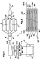
- reference number 1 indicates as a whole an item of equipment used to make packs of interleaved laminar articles. In a typical embodiment these may be handkerchiefs (which are dry or, with reference to a preferred field of application of the invention, premoistened).
- Equipment 1 comprises a number of stations or working units in cascade arrangement along the line of flow which results in the formation of packs P of individual interleaved articles from a starting material comprising a spool S of laminar material (e.g. cellulose wadding or a so-called non-woven fabric, which may be premoistened or subsequently moistened).
- laminar material e.g. cellulose wadding or a so-called non-woven fabric, which may be premoistened or subsequently moistened.
- the first station or unit in the equipment is for all purposes similar to the corresponding station in a device for the making of interleaved articles operating in accordance with the arrangement defined as the "in-line" arrangement described extensively in the introductory part of this description.
- the station in question comprises a device 2 to support spool S and unwind it in a controlled way towards a longitudinal cutting device 3.
- the laminar material on spool S is subdivided, in a known way, into a plurality of strips R1, R2, ..., Rn, which advance in parallel towards a shaping/interleaving device 4.
- the number n of strips obtained by cutting spool S is on the whole small (a typical value of n may, for example, be ten), which is usually very much less than the number of strips present in an in-line interleaving device of the conventional type, where the number n in fact identifies the number of articles included in the interleaving system (which can be quite high, even of the order of one hundred or more).
- strips R1, ..., R10 advance towards shaping/interleaving device 4 (the so-called "folder", of known structure) where strips R1, ..., R10 are combined together into a composite interleaved strip or web CW which has the profile shown diagrammatically in Figure 2 in transverse cross section.
- outer limbs project on opposite sides with respect to composite strip CW.
- one of the aforesaid outer strips is in turn folded into a general V-shaped profile; this results merely from the shaping imparted to corresponding strip R1 as a whole.
- Composite strip CW in the example illustrated comprising ten individual interleaved strips, is delivered to a cutting unit 5 of a known type, e.g. with counter-rotating knives.
- Unit 5 is designed to cut composite strip CW into individual lengths each having a length corresponding to a multiple of the final length which it is intended that the individual interleaved products collected in pack P should have (in principle the value of the multiple may also be equal to unity).
- the length of the pieces formed by cutting unit 5 may be 3 m, that is 15 times the length of the individual product.
- the pieces resulting from the action of cutting unit 5 are delivered to one or more secondary interleaving units indicated by 6.
- Each unit 6 has the function of receiving the pieces in sequence to combine them in turn in accordance with a general (secondary) interleaving system making use of the presence of projecting limbs W1 and W10 within the scope of each piece.
- more than one unit 6 is present (e.g. a number of four) is intended to take into account the fact that while the process of forming and cutting composite strip CW takes place in accordance with requirements of substantial continuity, the operation of individual units 6 is of a substantially discontinuous nature, as will be better seen below.
- the availability of more than one unit 6 which are capable of operating in parallel is therefore shown to be advantageous in that it makes it possible to subdivide or sort the flow of pieces originating from cutting unit 5 to various units 6 on the basis of a periodical distribution system by means of a distributor device 51 (of a known type).
- This arrangement operates in such a way that once one cycle of distribution of the pieces to the various units 6 has been completed, the immediately following piece in the flow originating from cutting unit 5 can be sorted or delivered to the unit 6 which was served first in the previous distribution cycle. With adequate coordination of the rate of flow of the pieces leaving cutting unit 5, the speed of operation and the number of units 6, this unit will then be available to receive this immediately subsequent piece which is intended to constitute the first piece in a new distribution cycle.
- the pieces of secondary composite strip CW' (produced by unit 6 in accordance with criteria better illustrated in the following) are reassembled in a continuous or substantially continuous flow by a device 71 (also of a known type) in order that a subsequent cutting operation can be performed.
- each unit 6 essentially comprises three components, at least some of which comprise driven belts (of a known type) identified by reference numbers 60, 61 and 62.
- the conveyors in question can receive the pieces as they move forward, that is in the direction of and synchronously with the forward movement with which these pieces arrive from unit 5 through distributor device 51.
- this description makes reference to an arrangement in which all three components 60, 61 and 62 comprise motor-driven belts, it will however be appreciated that, at least as far as component 62 is concerned, it is also possible to make use of different arrangements capable of ensuring the overturning function described below without this being accompanied by the capacity of performing a true and proper action of longitudinally conveying pieces of composite strip CW.
- the other two motor-driven belts 61, 62 are instead borne by corresponding structures 611 and 621 (of a known type, and therefore shown only diagrammatically in the appended drawings) which enable belts 61, 62 to each perform an overturning movement against belt 60 which is located in the central position. This takes place around the corresponding horizontal overturning axes X61 and X62, which are substantially coextensive with the direction in which the pieces advance. Axes X61 and X62 are located in positions alongside belt 60, and the corresponding overturning movement takes place under the effect of corresponding overturning motors (not illustrated, but of a known type).
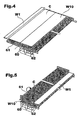
- the sequence of secondary interleaving operations shown diagrammatically in the sequence in Figures 4 to 8 is performed on the pieces deriving from the cutting action performed by unit 5.
- PLC programmable logic controller
- belts 60, 61, 62 are of a length corresponding to the length of the piece. All this with the further presence of registering means (of a known type and e.g. comprising optical barriers 63 which are illustrated in Figure 2 only). These registering means - which can of course also be constructed in different ways, e.g. using mere stops - act together with the motor drives for belts 60, 61 and 62 so that the forward movement of the pieces obtained from strip CW stops, when, for example, the ends of the pieces occupying the leading position in the forward movement are located so as to correspond to optical barriers 63. This condition corresponds to correct positioning of the pieces in unit 6 with a view to performance of the various operations described below, which are therefore preferably performed using pieces of strip CW which are stationary and "in register" with detectors 63.
- the overturning motor drive for belt 61 is activated so as to carry body C (and limb W1 projecting from it) over above limb W10 so as to achieve the folded position shown in Figure 5.
- body C overlies limb W10 supported on belt 60 with limb W1 now arranged in a position with respect to limb W10 which is exactly opposite that which it occupied in the starting conditions illustrated in Figure 4.
- a new piece obtained from composite strip CW through the effect of the sectioning action performed by action 5 is introduced into unit 6 in ways which are wholly identical to those described above.
- This new piece also comprises a body C' from which two end limbs W1' and W10' project.
- the overturning motor drive for belt 61 is then activated in the same way as previously described with reference to Figure 5.
- the overall result is to cause body C' of the new piece introduced into unit 6 to turn back over belt 60, that is above the piece of strip previously introduced into unit 1.
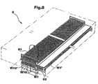
- This operation has the effect that body C' of the new piece of strip CW introduced into unit 6 is overturned onto body C of the piece previously introduced, but capturing limb W1 of the first piece introduced into unit 6 in a position between the two bodies C and C' and interlinked with limb W10' of the second piece.
- the interleaving operation performed in unit 6 substantially comprises the stages of:
- this operation comprises, in order, the stages of:
- the result of the aforesaid secondary interleaving operation is therefore to form a composite secondary strip CW' in general comprising a number k of sheets interleaved together - in a precisely uniform way.
- the subsequent composite strip CW' leaving unit or each unit 6 (corresponding to the result of the secondary interleaving operation and therefore comprising successive pieces of lengths equal to a multiple of the length of the individual product which it is desired to obtain as the final result of the interleaving operation) is finally fed to a cutting unit 7 (also of a known type) by means of bundling device 71.
- Unit 7 cuts the pieces of composite strip CW' originating from units 6 into individual packs P of length equal to the final length of the interleaved products.
- Packs P (which are intended to be delivered to a packaging station, which is not illustrated, but of a known type) each comprise a number k of products which are interleaved in a completely uniform way; as already mentioned, this expression is intended to indicate the fact that all k products obtained in the pack are connected together in accordance with a system of interleaving which is precisely the same throughout the entire extent of the pack, and therefore without any local differences resulting e.g. from the possible presence of breakable bridges provided to connect subsequent blocks of products comprising the pack.
- n the number of products k included in the pack obtained as the final result can be varied - to a level of distinction identified by the value of n - purely by acting on unit 6 in such a way as to selectively alter the number m of subsequent pieces of composite strip CW which are overlapped in the secondary interleaving action in the ways illustrated in Figures 4 to 8.
- these elements comprise a single complex of belts 60, 61, 62 which are capable of receiving successive pieces of strip CW to then perform the overturning and interleaving operation illustrated in the sequence of Figures 4 to 8.
Landscapes
- Folding Of Thin Sheet-Like Materials, Special Discharging Devices, And Others (AREA)
- Packaging Of Special Articles (AREA)
- Auxiliary Devices For And Details Of Packaging Control (AREA)
Description
- providing a first plurality (n) of strips (R1, ..., R10) of laminar material,
- subjecting the strips to a first interleaving operation so as to create a composite strip (CW) of interleaved structure with a first (R1) and a second (R10) strip of the said first plurality (n) located at end positions in the said composite strip (CW) and having a corresponding first (W1) and a corresponding second (W10) outer limb projecting with respect to the said composite strip (CW), and
- cutting the said composite strip (CW) into lengths by means of a transverse cutting operation (5),
an equipment to make packs (P) of interleaved laminar articles, comprising:
- a first interleaving unit (4) for acting on a first plurality (n) of strips (R1, ..., R10) of laminar material to subject these strips to a first interleaving operation and create a composite strip (CW) having an interleaved structure with a first (R1) and a second (R10) strip of the said first plurality (W) located at the terminal positions of the said composite strip (CW) and having a corresponding first (W1) and a corresponding second (W10) outer limb projecting with respect to the said composite strip (CW), and
- a cutting unit (5) to cut the said composite strip (CW) into lengths through a transverse cutting operation.
- Figure 1 shows the structure of equipment according to the invention in a general diagrammatical plan view,
- Figure 2 illustrates the structure of an intermediate product manufactured within the scope of the equipment, in diagrammatical terms for clarity of illustration,
- Figure 3 illustrates the structure and the operation of one of the parts of the equipment in Figure 1, and
- Figures 4 to 8 represent subsequent stages in the implementation of the process according to the invention implemented by the device in Figure 3.
- a body indicated by reference C (or C', in relation to the second piece considered) indicated in Figures 4 to 8 corresponding to the whole of strips R1, ..., R10 interleaved in the primary interleaving, with the exclusion of projecting limbs W1 and W10,
- a first projecting limb W1, W1' (which in the embodiment illustrated here is folded back on itself in a V shape), and
- the other projecting limb W10, W10' (which in the embodiment illustrated here is extended, and therefore free of fold lines).
- providing at least a first and a second piece of the aforesaid second plurality m each having a body C, C' and a corresponding first projecting limb W1, W1' and a corresponding second projecting limb W10, W10', and
- joining the first and second pieces in an interleaved condition with the first projecting limb W1 of the first piece and the second projecting limb W10' of the second piece folded back into a position in which they are interlinked and located between the said first and second pieces which are joined together.
- positioning the first piece with body C overturned onto corresponding second limb W1 which is folded back onto the body and corresponding first limb W1 continuing in a projecting condition (Figure 5),
- placing the second limb W10' of the second piece onto body C of the first piece (Figure 6),
- folding the first limb W1 of the first piece onto corresponding body C interlinking it with the second limb W10' of the second piece (Figure 7), and
- positioning the second piece with body C' overturned against the corresponding second limb W10' interlinked with the first limb W1 of the first piece (Figure 8).
- n represents the primary order of interleaving, that is the number of strips R1, ..., R10 (in the embodiment illustrated n = 10) interleaved in folding device 4, and
- m represents the number of pieces interleaved with
each other - in the secondary interleaving - in
unit 6.
Claims (14)
- Process for making packs (P) of interleaved laminar articles, comprising the operations of:further comprising the operations of:providing a first plurality (n) of strips (R1, ..., R10) of laminar material,subjecting the strips to a first interleaving operation so as to create a composite strip (CW) of interleaved structure with a first (R1) and a second (R10) strip of the said first plurality (n) located at end positions in the said composite strip (CW) and having a corresponding first (W1) and a corresponding second (W10) outer limb projecting with respect to the said composite strip (CW), andcutting the said composite strip (CW) into lengths by means of a transverse cutting operation (5),performing the said cutting operation (5) so as to give rise to successive separate pieces of the said composite strip (CW), andsubjecting a second plurality (m) of the said pieces to a second interleaving operation (6) performed by making use of the said corresponding projecting outer limbs (W1, W10) so as to give rise to a further composite strip (CW') comprising interleaved strips in a number (k) identified by the product of the said first (n) and the said second (m) pluralities.
- Process according to Claim 1, characterized in that it comprises the operation of subjecting the said subsequent composite strip (CW') to a further transverse cutting operation (7) so as to give rise to successive packs (P) of articles, each pack (P) comprising laminar articles which are interleaved in a uniform way in a number equal to the said number (k).
- Process according to Claim 1 or Claim 2, characterized in that the said second interleaving operation (6) comprises the stages of:providing at least a first and a second piece of the said second plurality (m) each having a body (C, C') and a corresponding first (W1, W1') and a corresponding second (W10, W10') projecting limb, andjoining the said first and second pieces in an interleaved way with the corresponding first projecting limb (W1) of the first piece and the corresponding second projecting limb (W10') of the second piece folded into a position in which they are interlinked and located between the said first and second pieces joined together.
- Process according to Claim 3, characterized in that it comprises, in order, the operations of:positioning the first piece with body (C) overturned onto the corresponding second limb (W10) folded back onto the body and the corresponding first limb (W1) maintained in a projecting condition,placing the second limb (W10') of the second piece onto the body (C) of the first piece,folding the first limb (W1) of the first piece onto the corresponding body (C) interlinking it with the second limb (W10') of the second piece, andplacing the second piece with its body (C') overturned against the corresponding second limb (W10') interlinked with the first limb (W1) of the first piece.
- Process according to any one of the preceding claims, characterized in that it comprises the operation of folding at least one (W1, W') of the said first and second outer limbs (W1, W10) into a general V-shaped configuration.
- Equipment to make packs (P) of interleaved laminar articles, comprising:whereby the said cutting unit (5) is configured so as to give rise to separate successive pieces of the said composite strip (CW) and in that at least a second interleaving unit (6) is provided to subject a second plurality (m) of the said pieces to a second interleaving operation (6) performed making use of the said corresponding outer projecting limbs (W1, W10) so as to give rise to a further composite strip (CW') comprising strips interleaved in a number (k) identified by the product of the said first (n) and the said second (m) pluralities.a first interleaving unit (4) for acting on a first plurality (n) of strips (R1,..., R10) of laminar material to subject these strips to a first interleaving operation and create a composite strip (CW) having an interleaved structure with a first (R1) and a second (R10) strip of the said first plurality (W) located at the terminal positions of the said composite strip (CW) and having a corresponding first (W1) and a corresponding second (W10) outer limb projecting with respect to the said composite strip (CW), anda cutting unit (5) to cut the said composite strip (CW) into lengths through a transverse cutting operation,
- Equipment according to Claim 6, characterized in that it comprises at least a further transverse cutting unit (7) acting on the said further composite strip (CW') so as to give rise to successive packs (P) of articles by cutting the said further composite strip (CW') into lengths, each pack (P) comprising laminar articles which are interleaved together in a uniform way in a number equal to the said number (k).
- Equipment according to Claim 6 or Claim 7, characterized in that the said at least one second interleaving unit (6) comprises:receiving means (60, 61, 62) for at least a first and a second piece of the said second plurality (m), each of the said pieces having a body (C, C') and a corresponding first (W1, W1') and a corresponding second (W10, W10') projecting limb, andoverturning means (61, 611, 62, 621) to join the said first and second pieces in an interleaved condition with the corresponding first projecting limb (W1) of the first piece and the corresponding second projecting limb (W10') of the second piece folded into an interlinked position and located between the said first and second pieces joined together.
- Equipment according to Claim 8, characterized in that the said at least one second interleaving unit (6) comprises:first overturning means (61, 611) to locate the first piece with its body (C) overturned onto the corresponding second limb (W10) folded back onto the body and the corresponding first limb (W1) remaining in a projecting condition,receiving means (60, 61) to position the second limb (W10') of the second piece on the body (C) of the first piece,second overturning means (62, 621) to fold the first limb (W1) of the first piece onto the corresponding body (C) interlinking it with the second limb (W10') of the second piece; the said first overturning means (611) positioning the second piece with the body (C') overturned against the corresponding second limb (W10') interlinked with the first limb (W1) of the first piece.
- Equipment according to Claim 8 or Claim 9, characterized in that the said receiving means comprise motor-driven conveyor members (60, 61, 62) adapted for receiving the said pieces as they move forward.
- Equipment according to any one of Claims 8 to 10, characterized in that the said overturning means comprise motor-driven conveyor members (60, 61, 62) adapted for receiving the said pieces as they move forward and have associated corresponding overturning motor drives (611, 621) acting about corresponding overturning axes (X61, X62) which are substantially coextensive with the direction in which the said pieces advance.
- Equipment according to Claim 8, characterized in that the said receiving means (60, 61, 62) are at least partly (60) capable of selectively moving in the direction of accumulation (D) of the said pieces of the said second plurality (m) which are interleaved through the effect of the said second interleaving operation.
- Equipment according to any one of Claims 6 to 12, characterized in that it also comprises registering means (63) for correctly positioning the pieces of the said second plurality (m) before proceeding with the said second interleaving operation.
- Equipment according to any one of Claims 6 to 13, characterized in that it comprises a plurality of the said second interleaving units (6) with associated means (51) for distribution of the said pieces separated from the said composite strip (CW) from the said cutting unit (5) to the second unit (6) interleaving the said plurality.
Priority Applications (4)
| Application Number | Priority Date | Filing Date | Title |
|---|---|---|---|
| DE69911607T DE69911607T2 (en) | 1999-10-15 | 1999-10-15 | Method and device for producing bundles of folded sheet-like articles |
| ES99830650T ES2207927T3 (en) | 1999-10-15 | 1999-10-15 | PROCEDURE AND EQUIPMENT TO PREPARE ARTICLE PACKAGES IN INTERCALATED SHEETS |
| EP99830650A EP1092664B1 (en) | 1999-10-15 | 1999-10-15 | Process and apparatus for realizing packs of interfolded laminar articles |
| US09/610,480 US6352251B1 (en) | 1999-10-15 | 2000-07-05 | Process and equipment for realizing packs of interfolded laminar articles |
Applications Claiming Priority (1)
| Application Number | Priority Date | Filing Date | Title |
|---|---|---|---|
| EP99830650A EP1092664B1 (en) | 1999-10-15 | 1999-10-15 | Process and apparatus for realizing packs of interfolded laminar articles |
Publications (2)
| Publication Number | Publication Date |
|---|---|
| EP1092664A1 EP1092664A1 (en) | 2001-04-18 |
| EP1092664B1 true EP1092664B1 (en) | 2003-09-24 |
Family
ID=8243629
Family Applications (1)
| Application Number | Title | Priority Date | Filing Date |
|---|---|---|---|
| EP99830650A Expired - Lifetime EP1092664B1 (en) | 1999-10-15 | 1999-10-15 | Process and apparatus for realizing packs of interfolded laminar articles |
Country Status (4)
| Country | Link |
|---|---|
| US (1) | US6352251B1 (en) |
| EP (1) | EP1092664B1 (en) |
| DE (1) | DE69911607T2 (en) |
| ES (1) | ES2207927T3 (en) |
Families Citing this family (3)
| Publication number | Priority date | Publication date | Assignee | Title |
|---|---|---|---|---|
| MX2011001995A (en) * | 2008-08-28 | 2011-05-25 | Georgia Pacific Consumer Prod | Folded sheet material and array of folded sheet materials. |
| US8490772B2 (en) | 2010-12-28 | 2013-07-23 | C. G. Bretting Manufacturing Co., Inc. | High speed interfolded log accumulator |
| CA3079321C (en) * | 2019-05-20 | 2026-04-07 | Pacproinc, Llc | Value added substrate interleaving system |
Family Cites Families (12)
| Publication number | Priority date | Publication date | Assignee | Title |
|---|---|---|---|---|
| US2403971A (en) * | 1941-03-31 | 1946-07-16 | Rca Corp | Method of making mica capacitors |
| US3845948A (en) * | 1972-07-17 | 1974-11-05 | Int Paper Co | Method of and apparatus for producing stacks of folded sheet material |
| US4061325A (en) * | 1976-08-19 | 1977-12-06 | Nicholas Marcalus | Methods and apparatus for interfolding endless paper webs |
| US4203584A (en) * | 1978-03-03 | 1980-05-20 | Marcal Paper Mills, Inc. | Methods and apparatus for interfolding bundles of interfolded webs |
| US4494741A (en) | 1981-03-20 | 1985-01-22 | John M. Rudolf | Tissue cutting and interfolding apparatus for Z webs |
| US4691908A (en) | 1986-01-06 | 1987-09-08 | Paper Converting Machine Company | Apparatus for interfolding |
| DE3915195A1 (en) * | 1989-05-10 | 1990-11-15 | Roland Man Druckmasch | DEVICE FOR STACKING FOR FOLDED SHEETS |
| JP2575247B2 (en) * | 1991-11-01 | 1997-01-22 | 克 米山 | Method and apparatus for multiple folding of single leaf web |
| US5299793A (en) * | 1992-11-23 | 1994-04-05 | C. G. Bretting Manufacturing Company, Inc. | Multi-panel refolding transfer system with rotating transfer clamp |
| US6090467A (en) * | 1993-10-12 | 2000-07-18 | Kimberly-Clark Australia Pty Limited | Method and apparatus to manufacture a towel or tissue stack |
| US5899447A (en) * | 1997-09-02 | 1999-05-04 | The Procter & Gamble Company | Apparatus for stacking pop-up towels |
| EP0955260B1 (en) | 1998-05-04 | 2003-01-22 | Fameccanica.Data S.p.A. | a process and a device for producing packs of interfolded laminar articles and respective product |
-
1999
- 1999-10-15 DE DE69911607T patent/DE69911607T2/en not_active Expired - Lifetime
- 1999-10-15 ES ES99830650T patent/ES2207927T3/en not_active Expired - Lifetime
- 1999-10-15 EP EP99830650A patent/EP1092664B1/en not_active Expired - Lifetime
-
2000
- 2000-07-05 US US09/610,480 patent/US6352251B1/en not_active Expired - Lifetime
Also Published As
| Publication number | Publication date |
|---|---|
| US6352251B1 (en) | 2002-03-05 |
| ES2207927T3 (en) | 2004-06-01 |
| DE69911607T2 (en) | 2004-06-24 |
| EP1092664A1 (en) | 2001-04-18 |
| DE69911607D1 (en) | 2003-10-30 |
Similar Documents
| Publication | Publication Date | Title |
|---|---|---|
| US7517309B2 (en) | Structure of interfolding machine | |
| CA1089504A (en) | Method of lapping webs and product | |
| JPS5920997Y2 (en) | Processed product package manufacturing equipment | |
| JPH03114739A (en) | Method and apparatus for producing paper-napkin or similar article | |
| US20070203007A1 (en) | Structure of interfolding machine with adjustable cut-off | |
| JP4891502B2 (en) | Method and apparatus for producing folded printed products | |
| KR102380336B1 (en) | Automated process system for manufacturing of a hand towel | |
| US4184591A (en) | Method for producing cigarette packages and packages produced by this method | |
| KR20000064386A (en) | Improved sheet products for use in pop-up distributors and their formation from elongated ribbons | |
| JPH11500655A (en) | Improved sheet products and methods of forming for use in pop-up dispensers | |
| US3402524A (en) | Apparatus for packaging articles | |
| GB1599462A (en) | Packet stacking apparatus | |
| US6352251B1 (en) | Process and equipment for realizing packs of interfolded laminar articles | |
| IT9009411A1 (en) | MACHINE FOR FOLDING AND GLUING LINES OF COATING PAPER ON CARDBOARD OR OTHER | |
| US7398630B2 (en) | Infeed assembly for a continuous motion wrapping assembly | |
| ITTO20011032A1 (en) | ,, PLANT FOR PACKAGING AND BAGGING PAPER ROLLS ,, | |
| ITBO20130664A1 (en) | APPARATUS FOR THE CONVEYANCE OF ARTICLES TO CORRESPONDING USES. | |
| JP4152727B2 (en) | Clothing folding machine | |
| EP0955260B1 (en) | a process and a device for producing packs of interfolded laminar articles and respective product | |
| US4061325A (en) | Methods and apparatus for interfolding endless paper webs | |
| CA1263849A (en) | Apparatus for supplying wrapping elements to packaging machines | |
| JPH0790971B2 (en) | Stacking method and apparatus thereof | |
| EP1232110B1 (en) | Package unit | |
| US5373680A (en) | Apparatus for folding and packaging of hygiene products such as tissues | |
| US3136277A (en) | Method of making paper bags |
Legal Events
| Date | Code | Title | Description |
|---|---|---|---|
| PUAI | Public reference made under article 153(3) epc to a published international application that has entered the european phase |
Free format text: ORIGINAL CODE: 0009012 |
|
| AK | Designated contracting states |
Kind code of ref document: A1 Designated state(s): DE ES FR GB IT SE |
|
| AX | Request for extension of the european patent |
Free format text: AL;LT;LV;MK;RO;SI |
|
| 17P | Request for examination filed |
Effective date: 20011002 |
|
| AKX | Designation fees paid |
Free format text: DE ES FR GB IT SE |
|
| 17Q | First examination report despatched |
Effective date: 20021128 |
|
| GRAH | Despatch of communication of intention to grant a patent |
Free format text: ORIGINAL CODE: EPIDOS IGRA |
|
| GRAS | Grant fee paid |
Free format text: ORIGINAL CODE: EPIDOSNIGR3 |
|
| GRAA | (expected) grant |
Free format text: ORIGINAL CODE: 0009210 |
|
| AK | Designated contracting states |
Kind code of ref document: B1 Designated state(s): DE ES FR GB IT SE |
|
| REG | Reference to a national code |
Ref country code: GB Ref legal event code: FG4D |
|
| REG | Reference to a national code |
Ref country code: SE Ref legal event code: TRGR |
|
| REF | Corresponds to: |
Ref document number: 69911607 Country of ref document: DE Date of ref document: 20031030 Kind code of ref document: P |
|
| REG | Reference to a national code |
Ref country code: ES Ref legal event code: FG2A Ref document number: 2207927 Country of ref document: ES Kind code of ref document: T3 |
|
| ET | Fr: translation filed | ||
| PLBE | No opposition filed within time limit |
Free format text: ORIGINAL CODE: 0009261 |
|
| STAA | Information on the status of an ep patent application or granted ep patent |
Free format text: STATUS: NO OPPOSITION FILED WITHIN TIME LIMIT |
|
| 26N | No opposition filed |
Effective date: 20040625 |
|
| REG | Reference to a national code |
Ref country code: FR Ref legal event code: PLFP Year of fee payment: 17 |
|
| PGFP | Annual fee paid to national office [announced via postgrant information from national office to epo] |
Ref country code: ES Payment date: 20150915 Year of fee payment: 17 |
|
| PGFP | Annual fee paid to national office [announced via postgrant information from national office to epo] |
Ref country code: FR Payment date: 20150923 Year of fee payment: 17 |
|
| PGFP | Annual fee paid to national office [announced via postgrant information from national office to epo] |
Ref country code: DE Payment date: 20151006 Year of fee payment: 17 Ref country code: IT Payment date: 20151019 Year of fee payment: 17 Ref country code: GB Payment date: 20151014 Year of fee payment: 17 |
|
| PGFP | Annual fee paid to national office [announced via postgrant information from national office to epo] |
Ref country code: SE Payment date: 20151013 Year of fee payment: 17 |
|
| REG | Reference to a national code |
Ref country code: DE Ref legal event code: R119 Ref document number: 69911607 Country of ref document: DE |
|
| GBPC | Gb: european patent ceased through non-payment of renewal fee |
Effective date: 20161015 |
|
| REG | Reference to a national code |
Ref country code: FR Ref legal event code: ST Effective date: 20170630 |
|
| PG25 | Lapsed in a contracting state [announced via postgrant information from national office to epo] |
Ref country code: DE Free format text: LAPSE BECAUSE OF NON-PAYMENT OF DUE FEES Effective date: 20170503 Ref country code: FR Free format text: LAPSE BECAUSE OF NON-PAYMENT OF DUE FEES Effective date: 20161102 Ref country code: GB Free format text: LAPSE BECAUSE OF NON-PAYMENT OF DUE FEES Effective date: 20161015 |
|
| PG25 | Lapsed in a contracting state [announced via postgrant information from national office to epo] |
Ref country code: SE Free format text: LAPSE BECAUSE OF NON-PAYMENT OF DUE FEES Effective date: 20161016 |
|
| PG25 | Lapsed in a contracting state [announced via postgrant information from national office to epo] |
Ref country code: IT Free format text: LAPSE BECAUSE OF NON-PAYMENT OF DUE FEES Effective date: 20161015 |
|
| PG25 | Lapsed in a contracting state [announced via postgrant information from national office to epo] |
Ref country code: ES Free format text: LAPSE BECAUSE OF FAILURE TO SUBMIT A TRANSLATION OF THE DESCRIPTION OR TO PAY THE FEE WITHIN THE PRESCRIBED TIME-LIMIT Effective date: 20030924 |
|
| REG | Reference to a national code |
Ref country code: ES Ref legal event code: FD2A Effective date: 20180626 |
|
| PG25 | Lapsed in a contracting state [announced via postgrant information from national office to epo] |
Ref country code: ES Free format text: LAPSE BECAUSE OF FAILURE TO SUBMIT A TRANSLATION OF THE DESCRIPTION OR TO PAY THE FEE WITHIN THE PRESCRIBED TIME-LIMIT Effective date: 20161016 |
|
| RIC2 | Information provided on ipc code assigned after grant |
Ipc: B65H 45/24 20060101AFI20000311BHEP |