EP1092661B1 - Conveying a recording web - Google Patents
Conveying a recording web Download PDFInfo
- Publication number
- EP1092661B1 EP1092661B1 EP00308935A EP00308935A EP1092661B1 EP 1092661 B1 EP1092661 B1 EP 1092661B1 EP 00308935 A EP00308935 A EP 00308935A EP 00308935 A EP00308935 A EP 00308935A EP 1092661 B1 EP1092661 B1 EP 1092661B1
- Authority
- EP
- European Patent Office
- Prior art keywords
- cam
- roller
- bar
- force
- gear
- Prior art date
- Legal status (The legal status is an assumption and is not a legal conclusion. Google has not performed a legal analysis and makes no representation as to the accuracy of the status listed.)
- Expired - Lifetime
Links
Images


Classifications
-
- B—PERFORMING OPERATIONS; TRANSPORTING
- B65—CONVEYING; PACKING; STORING; HANDLING THIN OR FILAMENTARY MATERIAL
- B65H—HANDLING THIN OR FILAMENTARY MATERIAL, e.g. SHEETS, WEBS, CABLES
- B65H27/00—Special constructions, e.g. surface features, of feed or guide rollers for webs
-
- B—PERFORMING OPERATIONS; TRANSPORTING
- B65—CONVEYING; PACKING; STORING; HANDLING THIN OR FILAMENTARY MATERIAL
- B65H—HANDLING THIN OR FILAMENTARY MATERIAL, e.g. SHEETS, WEBS, CABLES
- B65H20/00—Advancing webs
- B65H20/02—Advancing webs by friction roller
-
- B—PERFORMING OPERATIONS; TRANSPORTING
- B65—CONVEYING; PACKING; STORING; HANDLING THIN OR FILAMENTARY MATERIAL
- B65H—HANDLING THIN OR FILAMENTARY MATERIAL, e.g. SHEETS, WEBS, CABLES
- B65H2404/00—Parts for transporting or guiding the handled material
- B65H2404/10—Rollers
- B65H2404/13—Details of longitudinal profile
- B65H2404/134—Axle
- B65H2404/1342—Built-up, i.e. arrangement for mounting axle element on roller body
-
- B—PERFORMING OPERATIONS; TRANSPORTING
- B65—CONVEYING; PACKING; STORING; HANDLING THIN OR FILAMENTARY MATERIAL
- B65H—HANDLING THIN OR FILAMENTARY MATERIAL, e.g. SHEETS, WEBS, CABLES
- B65H2404/00—Parts for transporting or guiding the handled material
- B65H2404/10—Rollers
- B65H2404/14—Roller pairs
- B65H2404/143—Roller pairs driving roller and idler roller arrangement
-
- B—PERFORMING OPERATIONS; TRANSPORTING
- B65—CONVEYING; PACKING; STORING; HANDLING THIN OR FILAMENTARY MATERIAL
- B65H—HANDLING THIN OR FILAMENTARY MATERIAL, e.g. SHEETS, WEBS, CABLES
- B65H2404/00—Parts for transporting or guiding the handled material
- B65H2404/10—Rollers
- B65H2404/14—Roller pairs
- B65H2404/144—Roller pairs with relative movement of the rollers to / from each other
- B65H2404/1441—Roller pairs with relative movement of the rollers to / from each other involving controlled actuator
-
- B—PERFORMING OPERATIONS; TRANSPORTING
- B65—CONVEYING; PACKING; STORING; HANDLING THIN OR FILAMENTARY MATERIAL
- B65H—HANDLING THIN OR FILAMENTARY MATERIAL, e.g. SHEETS, WEBS, CABLES
- B65H2404/00—Parts for transporting or guiding the handled material
- B65H2404/10—Rollers
- B65H2404/15—Roller assembly, particular roller arrangement
Definitions
- This invention relates to conveying a recording medium and, more particularly, to varying an amount of force applied to the recording medium by conveying rollers.
- Recording media is conveyed using rollers which "pinch" the media to move it to/from an imaging location.
- the same amount of pinch force was applied by the rollers to convey media regardless of the thickness (and thus the stiffness) of the media. This can result in poorly formed images since different amounts of force may be required to accurately convey "thin” media (on the order of 0.004 inches thick) than to accurately convey "thick” media (on the order of 0.007 to 0.008 inches thick).
- DE 3545304A discloses apparatus for transporting thin materials, such as sheets or webs or paper. The materials are pressed by a roller against the periphery of a drivable transport roller.
- the apparatus includes a first and second conveying device, a cutting device and a clamping device.
- GB-A-2121009 discloses a device for adjusting the nip pressure of rollers feeding photosensitive web material in a duplicating camera.
- the pressure may be changed or relieved by adjustment of a cam bearing on a spring loaded roller support.
- apparatus which conveys a recording medium, having the features of claim 1.
- the preferred embodiment of the invention features an apparatus which conveys a recording medium.
- the apparatus includes first and second rollers that define a common area through which the recording medium is conveyed.
- the first and second rollers contact the recording medium in the common area and rotate in concert to convey the recording medium from the common area.
- a cam leverages the second roller to vary an amount of nonzero force applied to the recording medium in the common area.
- the advantages may be one or more of the following.
- the second roller By leveraging the second roller, it is possible to vary the amount of force applied to the recording medium based, for example, on the thickness of the recording medium.
- the invention makes it possible to form accurate images on recording media of different thicknesses.
- the preferred embodiment may include one or more of the following features.
- the common area is defined by surfaces of the first and second rollers.
- the cam may be movable into plural positions, each of which leverages the second roller differently to change the amount of force.
- the apparatus may include a bar arranged in a common mechanical coupling with the second roller. The cam is in contact with the bar and is movable relative to the bar to leverage the second roller.
- the first roller may be a capstan roller and the second roller may be a pinch roller.
- the apparatus may include a control mechanism for controlling the cam to leverage the second roller.
- the control mechanism comprises a first gear connected to the cam, a second gear connected to the first gear by a belt which couples motion of the first gear to the second gear, and a lever which mates to a receptacle in the second gear and which is movable to control motion of the second gear.
- the second gear may include plural receptacles.
- the lever is capable of mating to each of these receptacles.
- the lever controls motion of the second gear to apply a first range of force when mated to a first one of the plural receptacles.
- the lever controls motion of the second gear to apply a second range of force when mated to a second one of the plural receptacles.
- the apparatus may include mechanical stops arranged relative to the lever for limiting a range of motion of the lever.
- the apparatus may include a member which is in a common mechanical coupling with plural pinch rollers (including the second roller) and a bar which couples to the member and which is in contact with the cam.
- the cam is rotatable relative to the bar to leverage the plural pinch rollers via the bar and the member.
- the apparatus may include a second cam on an opposite side of the member from the first cam, and a second bar which couples to the member and which is in contact with the second cam.
- the second cam is rotatable relative to the second bar to leverage the plural pinch rollers via the second bar and the member.
- the apparatus may include a mounting block which is coupled to the second roller, a member which is coupled to the mounting block, and a bar which is coupled to the member and which is in contact with the cam.
- the cam is rotatable relative to the bar to leverage the second roller via the bar, the member, and the mounting block.
- the mounting block may include a spring in contact with the member and the second roller for controlling motion of the second roller during leveraging.
- the apparatus may be part of a laser imaging system.
- the preferred embodiment also features an apparatus for conveying a recording medium which includes conveying means for conveying the recording medium.
- the conveying means applies an amount of force to the recording medium during conveying.
- Changing means changes the amount of force.
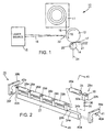
- Fig. 1 shows a laser imaging system 10.
- Laser imaging system 10 includes media supply 11, capstan roller 12, pinch roller 14, and a laser source 15.
- System 10 also include electronics (not shown) for controlling the motion of rollers 12 and 14 and optics (not shown) for controlling scanning of laser beam 18 to form images on medium 16.
- recording medium 16 is loaded, from media supply 11, to a common area 17 between the surfaces of capstan roller 12 and pinch roller 14.
- Recording medium 16 may be any type of medium; however, photosensitive metal film is used in this embodiment.
- Rollers 12 and 14 contact recording medium 16 in common area 17 and rotate in concert (in the directions of arrows 19 and 20) to convey recording medium 16 away from common area 17 (in the direction of arrow 21).
- laser beam 18 is scanned over its surface roughly at plane 22, thereby exposing recording medium 16. This exposure changes properties of the recording medium 16 which, when further processed, results in the formation of an image at the points of exposure.
- pinch roller 14 is leveraged (i.e., moved) relative to capstan roller 12 (which remains substantially immobile) to vary the amount of this pinch force.
- Mechanisms for controlling the movement of pinch roller 14 are as follows.
- Pinch roller assembly 25 includes plural pinch rollers 26a to 26e, each of which is mechanically coupled to member 27. When so coupled, pinch rollers 26a to 26e move in concert with member 27, thus moving as a single roller, more or less. Pinch rollers 26a to 26e contact a single capstan roller (not shown in Fig. 2) when the pinch force is applied (via member 27, see below); however, multiple capstan rollers may also be used.
- the mechanical coupling to member 27 is the same for all of pinch rollers 26a to 26e; therefore, it will only be described with respect to pinch roller 26a.
- Pinch roller 26a is coupled to mounting blocks 29a and 29b, which do not interfere with conveying of the recording medium. These mounting blocks have a common design; therefore, only one mounting block 29a is described.
- Mounting block 29a includes a hole 30 which receives a shaft 31 of pinch roller 26a, thereby allowing pinch roller 26a to rotate relative to mounting block 29a.
- Flanges 32a and 32b on mounting block 29a align with sides 34a and 34b, respectively, on member 27 to align the mounting block to member 27.
- Mounting block 29a is fixed to member 27 using screws or the like.
- Spring 35 Internal to mounting block 29a is an assembly comprised of a spring 35 and a plunger 36.
- Spring 35 is interposed between member 27 and plunger 36.
- Plunger 36 contacts spring 35 and shaft 31, and moves laterally (e.g., "up” and “down") relative to pinch roller 26a as force is applied to pinch roller 26a.
- Spring 35 restricts the motion of plunger 36 (and thus the motion of pinch roller 26a), while still providing pinch roller 26a with some freedom of lateral movement relative to the recording medium during the application of a pinch force.
- pinch roller 26a, mounting block 29a, and member 27 are in a common mechanical coupling with (L-shaped) bar 39a.
- Bar 39a is fixed (via screws or the like) to a side 40a of member 27.
- a similar such bar 39b is fixed to an opposite side 40b of member 27. Bars 39a and 39b operate identically; therefore, only bar 39a is described.
- cam 42a In contact with the underside 41 of bar 39a is cam 42a (bar 39b contacts a similar cam 42b).
- Cam 42a is movable (that is, rotatable) relative to bar 39a to leverage bar 39a and, in turn, member 27, mounting blocks 29a to 29f, and pinch rollers 26a to 26e. This leverage causes pinch rollers 26a to 26e to move into closer (that is, tighter) contact with the capstan roller, thereby increasing the amount of pinch force applied to a recording medium between the pinch rollers and the capstan roller.
- FIG. 3 a cut-away view of assembly 25 taken along lines 45 (Fig. 2) is shown.
- Cam 42a has a radius which varies relative to its center shaft 50.
- This center shaft is rotatable and fixed (to side plate 51, described below), meaning that center shaft 50 is laterally immobile relative to bar 39a but can rotate about its own axis (arrow 52).
- variations in the radius of cam 42a will cause bar 39a to move upwards (arrow 54) or downwards (arrow 55), depending upon which radius of cam 42a comes into contact with bar 39a.
- cam 42a is rotated to a position where radius 59 is in contact with bar 39a (as shown), a low (nonzero) pinch force will result (for use, e.g., with thin recording media) since radius 59 is relatively small. If cam 42a is rotated to a position where radius 60 is in contact with bar 39a, a higher (nonzero) pinch force will result (for use, e.g., with thick recording media) since radius 60 is relatively large. Cam 42a is also provided with a "media loading" radius 61.
- This radius is small relative to the remainder of cam 42a and, when cam 42a is rotated to a position where this radius 61 is in contact with bar 39a, a gap (or zero pinch force) will be produced between rollers 26a and 57. This gap is used to load new media to common area 62 between rollers 26a and 57.
- a control mechanism 64 is shown for controlling cam 42a (cam 42a itself is not visible in Fig. 4) to leverage pinch rollers 26a to 26e.
- Control mechanism 64 is connected to side plate 51, which is interposed between assembly 25 (Fig. 2) and electro-mechanical devices (not shown) for controlling the rotation of capstan roller 57 (the pinch rollers are passive in that they rotate when capstan roller 57 rotates).
- Control mechanism 64 includes a master gear 65 and a slave gear 66, which are mounted to shafts 67 and 69, respectively, on side plate 51.
- Shaft 67 is fixed.
- Master gear 65 rotates around shaft 67 and slave gear 66 rotates shaft 69 to rotate the cam.
- Slave gear 66 is mounted on the center shaft (shaft 69) of the cam, which protrudes from side plate 51.
- a belt 70 connects master gear 65 to slave gear 66, and thus couples the motion (rotation) of master gear 65 to slave gear 66.
- Belt 70 may include teeth (not shown) which mate to corresponding teeth (also not shown) on master gear 65 and slave gear 66.
- rotating master gear 65 causes slave gear 66 to rotate which, in turn, causes the cam to rotate (since slave gear 66 is coupled to the center shaft of the cam).
- a lever 71 is provided for controlling rotation of master gear 65 manually (and thus for changing the amount of pinching force).
- Receptacles 72 and 74 e.g., holes
- lever 71 is used to control rotation of master gear 65.
- mechanical stops 76a and 76b are arranged relative to lever 71 for limiting the range of rotation of the lever (and thus of master gear 65, slave gear 66, and the cam).
- Mechanical stops 76a and 76b and receptacles 72 and 74 are arranged so that, when lever 71 is mated to receptacle 74, cam 42a can be rotated between radius 60 (high pinch force) and radius 61 (media load) (Fig. 3); and, when lever 71 is mated to receptacle 72, cam 42a can be rotated between radius 59 (low pinch force) and radius 61.
- Lever 71 could be mated to outer portion 75 differently.
- lever 71 could be mated to a track on outer portion 75 which includes plural slots (similar to a manual gear shift). The lever could be moved along the track into (or out of) these slots to vary the amount of applied force.
- additional radii could be provided on the cam, again to provide further pinch force variations.
- the invention could be incorporated into a variety of different types of imaging systems using any type of recording medium, and is not limited to the specific configurations set forth above.
Landscapes
- Delivering By Means Of Belts And Rollers (AREA)
Description
- This invention relates to conveying a recording medium and, more particularly, to varying an amount of force applied to the recording medium by conveying rollers.
- Recording media is conveyed using rollers which "pinch" the media to move it to/from an imaging location. Heretofore, the same amount of pinch force was applied by the rollers to convey media regardless of the thickness (and thus the stiffness) of the media. This can result in poorly formed images since different amounts of force may be required to accurately convey "thin" media (on the order of 0.004 inches thick) than to accurately convey "thick" media (on the order of 0.007 to 0.008 inches thick).
- DE 3545304A discloses apparatus for transporting thin materials, such as sheets or webs or paper. The materials are pressed by a roller against the periphery of a drivable transport roller.
- DE 19748789A discloses apparatus for transversely cutting a paper web. The apparatus includes a first and second conveying device, a cutting device and a clamping device.
- GB-A-2121009 discloses a device for adjusting the nip pressure of rollers feeding photosensitive web material in a duplicating camera. The pressure may be changed or relieved by adjustment of a cam bearing on a spring loaded roller support.
- According to the invention, there is provided apparatus, which conveys a recording medium, having the features of claim 1.
- The preferred embodiment of the invention features an apparatus which conveys a recording medium. The apparatus includes first and second rollers that define a common area through which the recording medium is conveyed. The first and second rollers contact the recording medium in the common area and rotate in concert to convey the recording medium from the common area. A cam leverages the second roller to vary an amount of nonzero force applied to the recording medium in the common area.
- Among the advantages may be one or more of the following. By leveraging the second roller, it is possible to vary the amount of force applied to the recording medium based, for example, on the thickness of the recording medium. Thus, when used with an imaging apparatus, the invention makes it possible to form accurate images on recording media of different thicknesses.
- The preferred embodiment may include one or more of the following features. The common area is defined by surfaces of the first and second rollers. The cam may be movable into plural positions, each of which leverages the second roller differently to change the amount of force. The apparatus may include a bar arranged in a common mechanical coupling with the second roller. The cam is in contact with the bar and is movable relative to the bar to leverage the second roller. The first roller may be a capstan roller and the second roller may be a pinch roller.
- The apparatus may include a control mechanism for controlling the cam to leverage the second roller. The control mechanism comprises a first gear connected to the cam, a second gear connected to the first gear by a belt which couples motion of the first gear to the second gear, and a lever which mates to a receptacle in the second gear and which is movable to control motion of the second gear. The second gear may include plural receptacles. The lever is capable of mating to each of these receptacles. The lever controls motion of the second gear to apply a first range of force when mated to a first one of the plural receptacles. The lever controls motion of the second gear to apply a second range of force when mated to a second one of the plural receptacles. The apparatus may include mechanical stops arranged relative to the lever for limiting a range of motion of the lever.
- The apparatus may include a member which is in a common mechanical coupling with plural pinch rollers (including the second roller) and a bar which couples to the member and which is in contact with the cam. The cam is rotatable relative to the bar to leverage the plural pinch rollers via the bar and the member. The apparatus may include a second cam on an opposite side of the member from the first cam, and a second bar which couples to the member and which is in contact with the second cam. The second cam is rotatable relative to the second bar to leverage the plural pinch rollers via the second bar and the member.
- The apparatus may include a mounting block which is coupled to the second roller, a member which is coupled to the mounting block, and a bar which is coupled to the member and which is in contact with the cam. The cam is rotatable relative to the bar to leverage the second roller via the bar, the member, and the mounting block. The mounting block may include a spring in contact with the member and the second roller for controlling motion of the second roller during leveraging. The apparatus may be part of a laser imaging system.
- The preferred embodiment also features an apparatus for conveying a recording medium which includes conveying means for conveying the recording medium. The conveying means applies an amount of force to the recording medium during conveying. Changing means changes the amount of force. Among the features that may be included is a controlling means for controlling the changing means manually.
- Other features and advantages of the invention will become apparent from the following description and claims.
- The invention will now be described, by way of example, with reference to the accompanying drawings in which:
- Fig. 1 is a side view of a laser imaging system.
- Fig. 2 is a perspective view of a pinch roller assembly, including a mechanism which controls an amount of force applied by pinch rollers in the assembly.
- Fig. 3 is a cut-away view of the pinch roller assembly.
- Fig. 4 is a perspective view of a mechanism for controlling the amount of applied pinch force.
- Fig. 5 is a side view of the mechanism of Fig. 4.
-
- Fig. 1 shows a
laser imaging system 10.Laser imaging system 10 includesmedia supply 11,capstan roller 12,pinch roller 14, and alaser source 15.System 10 also include electronics (not shown) for controlling the motion ofrollers laser beam 18 to form images onmedium 16. - In operation,
recording medium 16 is loaded, frommedia supply 11, to acommon area 17 between the surfaces ofcapstan roller 12 andpinch roller 14.Recording medium 16 may be any type of medium; however, photosensitive metal film is used in this embodiment.Rollers contact recording medium 16 incommon area 17 and rotate in concert (in the directions ofarrows 19 and 20) to conveyrecording medium 16 away from common area 17 (in the direction of arrow 21). While recordingmedium 16 is being conveyed in this manner,laser beam 18 is scanned over its surface roughly atplane 22, thereby exposingrecording medium 16. This exposure changes properties of therecording medium 16 which, when further processed, results in the formation of an image at the points of exposure. - During conveying, a pinch force (in the direction of arrow 24) is provided to recording
medium 16 bypinch roller 14.Pinch roller 14 is leveraged (i.e., moved) relative to capstan roller 12 (which remains substantially immobile) to vary the amount of this pinch force. Mechanisms for controlling the movement ofpinch roller 14 are as follows. - Referring to Fig. 2, a view of these mechanisms in a
pinch roller assembly 25 is shown.Pinch roller assembly 25 includesplural pinch rollers 26a to 26e, each of which is mechanically coupled tomember 27. When so coupled,pinch rollers 26a to 26e move in concert withmember 27, thus moving as a single roller, more or less.Pinch rollers 26a to 26e contact a single capstan roller (not shown in Fig. 2) when the pinch force is applied (viamember 27, see below); however, multiple capstan rollers may also be used. - The mechanical coupling to
member 27 is the same for all ofpinch rollers 26a to 26e; therefore, it will only be described with respect to pinchroller 26a. Pinchroller 26a is coupled to mountingblocks mounting block 29a is described. Mountingblock 29a includes ahole 30 which receives ashaft 31 ofpinch roller 26a, thereby allowingpinch roller 26a to rotate relative to mountingblock 29a.Flanges block 29a align withsides member 27 to align the mounting block tomember 27. Mountingblock 29a is fixed tomember 27 using screws or the like. - Internal to mounting
block 29a is an assembly comprised of aspring 35 and aplunger 36.Spring 35 is interposed betweenmember 27 andplunger 36.Plunger 36contacts spring 35 andshaft 31, and moves laterally (e.g., "up" and "down") relative to pinchroller 26a as force is applied to pinchroller 26a.Spring 35 restricts the motion of plunger 36 (and thus the motion ofpinch roller 26a), while still providingpinch roller 26a with some freedom of lateral movement relative to the recording medium during the application of a pinch force. - As shown in Fig. 2,
pinch roller 26a, mountingblock 29a, andmember 27 are in a common mechanical coupling with (L-shaped)bar 39a.Bar 39a is fixed (via screws or the like) to aside 40a ofmember 27. A similarsuch bar 39b is fixed to anopposite side 40b ofmember 27.Bars bar 39a is described. - In contact with the
underside 41 ofbar 39a iscam 42a (bar 39b contacts asimilar cam 42b).Cam 42a is movable (that is, rotatable) relative to bar 39a to leveragebar 39a and, in turn,member 27, mountingblocks 29a to 29f, andpinch rollers 26a to 26e. This leverage causespinch rollers 26a to 26e to move into closer (that is, tighter) contact with the capstan roller, thereby increasing the amount of pinch force applied to a recording medium between the pinch rollers and the capstan roller. - Referring to Fig. 3, a cut-away view of
assembly 25 taken along lines 45 (Fig. 2) is shown.Cam 42a has a radius which varies relative to itscenter shaft 50. This center shaft is rotatable and fixed (toside plate 51, described below), meaning thatcenter shaft 50 is laterally immobile relative to bar 39a but can rotate about its own axis (arrow 52). Ascenter shaft 50 and thuscam 42a rotates, variations in the radius ofcam 42a will causebar 39a to move upwards (arrow 54) or downwards (arrow 55), depending upon which radius ofcam 42a comes into contact withbar 39a. Asbar 39a moves, so doesmember 27, mountingblock 29a, and pinchroller 26a, thereby affecting the amount of pinch force applied to medium 56 bypinch roller 26a andcapstan roller 57. - For example, if
cam 42a is rotated to a position whereradius 59 is in contact withbar 39a (as shown), a low (nonzero) pinch force will result (for use, e.g., with thin recording media) sinceradius 59 is relatively small. Ifcam 42a is rotated to a position whereradius 60 is in contact withbar 39a, a higher (nonzero) pinch force will result (for use, e.g., with thick recording media) sinceradius 60 is relatively large.Cam 42a is also provided with a "media loading"radius 61. This radius is small relative to the remainder ofcam 42a and, whencam 42a is rotated to a position where thisradius 61 is in contact withbar 39a, a gap (or zero pinch force) will be produced betweenrollers common area 62 betweenrollers - Referring now to Fig. 4, a
control mechanism 64 is shown for controllingcam 42a (cam 42a itself is not visible in Fig. 4) to leveragepinch rollers 26a to 26e.Control mechanism 64 is connected toside plate 51, which is interposed between assembly 25 (Fig. 2) and electro-mechanical devices (not shown) for controlling the rotation of capstan roller 57 (the pinch rollers are passive in that they rotate whencapstan roller 57 rotates). -
Control mechanism 64 includes amaster gear 65 and aslave gear 66, which are mounted toshafts side plate 51.Shaft 67 is fixed.Master gear 65 rotates aroundshaft 67 andslave gear 66 rotatesshaft 69 to rotate the cam.Slave gear 66 is mounted on the center shaft (shaft 69) of the cam, which protrudes fromside plate 51. Abelt 70 connectsmaster gear 65 toslave gear 66, and thus couples the motion (rotation) ofmaster gear 65 toslave gear 66.Belt 70 may include teeth (not shown) which mate to corresponding teeth (also not shown) onmaster gear 65 andslave gear 66. In operation, rotatingmaster gear 65causes slave gear 66 to rotate which, in turn, causes the cam to rotate (sinceslave gear 66 is coupled to the center shaft of the cam). - A
lever 71 is provided for controlling rotation ofmaster gear 65 manually (and thus for changing the amount of pinching force).Receptacles 72 and 74 (e.g., holes) are provided on anouter portion 75 ofmaster gear 65 for receivinglever 71. When mated to one of these receptacles,lever 71 is used to control rotation ofmaster gear 65. - As shown in Figs. 4 and 5,
mechanical stops master gear 65,slave gear 66, and the cam). Mechanical stops 76a and 76b andreceptacles lever 71 is mated to receptacle 74,cam 42a can be rotated between radius 60 (high pinch force) and radius 61 (media load) (Fig. 3); and, whenlever 71 is mated to receptacle 72,cam 42a can be rotated between radius 59 (low pinch force) andradius 61. Thus, by movinglever 71 from one receptacle to another, it is possible to change, and/or control, the amount of the pinch force manually. - Other embodiments not described herein are also included within the scope of the following claims. For example, more than two receptacles may be provided on
outer portion 75 ofmaster gear 65. These additional receptacles would provide additional pinch force variations.Lever 71 could be mated toouter portion 75 differently. For example,lever 71 could be mated to a track onouter portion 75 which includes plural slots (similar to a manual gear shift). The lever could be moved along the track into (or out of) these slots to vary the amount of applied force. Such a configuration eliminates the need to removelever 71 to reset the amount of force. Also, additional radii could be provided on the cam, again to provide further pinch force variations. The invention could be incorporated into a variety of different types of imaging systems using any type of recording medium, and is not limited to the specific configurations set forth above.
Claims (18)
- An apparatus which conveys a recording medium (16), comprising:first and second rollers (12, 14) which define a common area through which the recording medium is conveyed, the first and second rollers contacting the recording medium in the common area and rotating in concert to convey the recording medium from the common area;a cam (42a) which leverages the second roller to vary an amount of nonzero force applied to the recording medium in the common area characterised by,a control mechanism (64) for controlling the cam to leverage the second roller, comprising:a first gear (66) connected to the cam;a second gear (65) connected to the first gear by a belt (70) which couples motion of the first gear to the second gear, the second gear including a receptacle (72); anda lever (71) which mates to the receptacle and which is movable to control motion of the second gear.
- The apparatus of claim 1, wherein the common area is defined by surfaces of the first 12 and second 14 rollers.
- The apparatus of claim 1, wherein the cam 42a is movable into plural positions, each of the plural positions for leveraging the second roller 14 differently to change the amount of force.
- The apparatus of claim 1, wherein:the second gear 65 includes plural receptacles; andthe lever 71 is capable of mating to each of the plural receptacles, the lever controlling motion of the second gear 65 to apply a first range of force when mated to a first one of the plural receptacles, and the lever controlling motion of the second gear 65 to apply a second range of force when mated to a second one of the plural receptacles.
- The apparatus of claim 1, further comprising mechanical stops 76a, 76b arranged relative to the lever for limiting a range of motion of the lever 71.
- The apparatus of claim 1, further comprising:wherein the cam 42a is in contact with the bar and is movable relative to the bar to leverage the second roller.a bar 39a arranged in a common mechanical coupling with the second roller 14;
- The apparatus of claim 1, wherein the first roller 12 has a larger diameter than the second roller 14.
- The apparatus of claim 1, wherein the control mechanism further comprises:wherein the cam 42a is rotatable relative to the bar 39a to leverage the second roller 14 via the bar 39a and the member 27.a member 27 which is in a common mechanical coupling with the second roller 14; anda bar 39a which couples to the member 27 and which is in contact with the cam 42a;
- The apparatus of claim 10, further comprising: 42awherein the second cam 42b is rotatable relative to the second bar 39b to leverage the second rolle 14 via the second bar 27b and the member 27.a second cam 42b located on an opposite side of the member as the first cam 42a; anda second bar 39b which couples to the member 27 and which is in contact with the second cam 42b;
- The apparatus of claim 1, further comprising:wherein the cam 42a, 42b is rotatable relative to the bar 39a, 39b to leverage the second roller 14 via the bar 39a, 39b, the member 27, and the mounting block 29a-29f, and wherein the mounting block 29a-29f includes a spring 35 in contact with the member 27 and the second roller 14 for controlling motion of the second roller 14 during leveraging.a mounting block 29a-29f which is coupled to the second roller 14;a member 27 which is coupled to the mounting block 29a-29f; anda bar 39a, 39b which is coupled to the member and which is in contact with the cam 42a,42b,
- The apparatus of claim 1, wherein the apparatus is a part of a laser imaging system.
- The apparatus of claim 1, wherein the cam which 42a, 42b leverages the second roller 14 to vary an amount of force applied to the recording medium between at least a first nonzero force, a second nonzero force, and a zero force.
- The apparatus of claim 12, wherein the amount of force is zero when the cam is not leveraging the second roller 14.
- The apparatus of claim 12, wherein the amount of force is nonzero when the cam is leveraging the second roller 14.
- The apparatus of claim 8, wherein the amount of force is nonzero when the cam is leveraging the second roller 14.
- The apparatus of claim 1, wherein the amount of force is zero when the cam is not leveraging the second roller 14.
- The apparatus of claim 1, wherein the amount of force is nonzero when the cam is leveraging the second roller 14.
- The apparatus of claim 6, further comprising:a second cam 42b located on an opposite side of the control mechanism as the first cam 42a; anda second bar 39b which is in contact with the second cam 42b, wherein the second cam 42b is rotatable relative to the second bar 39b.
Applications Claiming Priority (2)
| Application Number | Priority Date | Filing Date | Title |
|---|---|---|---|
| US09/419,464 US6334565B1 (en) | 1999-10-15 | 1999-10-15 | Conveying a recording medium |
| US419464 | 1999-10-15 |
Publications (2)
| Publication Number | Publication Date |
|---|---|
| EP1092661A1 EP1092661A1 (en) | 2001-04-18 |
| EP1092661B1 true EP1092661B1 (en) | 2004-08-04 |
Family
ID=23662388
Family Applications (1)
| Application Number | Title | Priority Date | Filing Date |
|---|---|---|---|
| EP00308935A Expired - Lifetime EP1092661B1 (en) | 1999-10-15 | 2000-10-11 | Conveying a recording web |
Country Status (3)
| Country | Link |
|---|---|
| US (1) | US6334565B1 (en) |
| EP (1) | EP1092661B1 (en) |
| DE (1) | DE60012647T2 (en) |
Families Citing this family (2)
| Publication number | Priority date | Publication date | Assignee | Title |
|---|---|---|---|---|
| US7066463B2 (en) * | 2002-04-08 | 2006-06-27 | Ecrm Incorporated | System and method for sheet transporting using dual capstan rollers |
| US8905537B2 (en) | 2012-05-30 | 2014-12-09 | Hewlett-Packard Development Company, L.P. | Media handling device including a carrier structure for a set of starwheels |
Family Cites Families (12)
| Publication number | Priority date | Publication date | Assignee | Title |
|---|---|---|---|---|
| US3148819A (en) * | 1962-09-04 | 1964-09-15 | Ampex | Pinch roller actuating mechanism |
| US3257056A (en) * | 1964-01-27 | 1966-06-21 | Midwestern Instr Inc | Pressure adjustment mechanism for magnetic tape capstan |
| US3572571A (en) * | 1968-09-20 | 1971-03-30 | Victor Company Of Japan | Pinch roller device for magnetic recording and reproducing apparatus |
| US3669331A (en) * | 1971-03-04 | 1972-06-13 | Walter Renold | Free floating pressure roller means and retracting mechanism for film drive |
| JPS58170619U (en) * | 1982-05-10 | 1983-11-14 | 大日本スクリ−ン製造株式会社 | Nitspro roller floating device for sending out roll paper sensitive material |
| DE3545304A1 (en) * | 1985-12-20 | 1987-07-02 | Helmut Steinhilber | Device for conveying thin materials such as leaves, sheets and webs in particular of paper |
| JPS6326182U (en) * | 1986-08-02 | 1988-02-20 | ||
| JPH04558U (en) * | 1990-04-17 | 1992-01-06 | ||
| US5344058A (en) * | 1991-03-05 | 1994-09-06 | Ecrm Trust | Method and apparatus for precisely driving film material |
| US5913470A (en) * | 1997-01-13 | 1999-06-22 | Scribner; Albert Willis | Roll feeder |
| DE19748789C2 (en) * | 1997-11-05 | 2000-05-25 | Boewe Systec Ag | Device for cross cutting a paper web |
| JP3486545B2 (en) * | 1997-11-27 | 2004-01-13 | キヤノン株式会社 | Image forming device |
-
1999
- 1999-10-15 US US09/419,464 patent/US6334565B1/en not_active Expired - Fee Related
-
2000
- 2000-10-11 DE DE60012647T patent/DE60012647T2/en not_active Expired - Fee Related
- 2000-10-11 EP EP00308935A patent/EP1092661B1/en not_active Expired - Lifetime
Also Published As
| Publication number | Publication date |
|---|---|
| US6334565B1 (en) | 2002-01-01 |
| DE60012647T2 (en) | 2005-02-03 |
| DE60012647D1 (en) | 2004-09-09 |
| EP1092661A1 (en) | 2001-04-18 |
Similar Documents
| Publication | Publication Date | Title |
|---|---|---|
| EP0072466B1 (en) | Web-tracking apparatus | |
| CN100379571C (en) | Sheet conveying apparatus and image forming apparatus and image reading device | |
| US5162857A (en) | Sheet conveyer having a sheet aligner | |
| US5676477A (en) | Sheet carrying apparatus | |
| JP4630652B2 (en) | Fixing apparatus and image forming apparatus | |
| US6322067B1 (en) | Sheet loading apparatus for image forming device | |
| JPH1083124A (en) | Image forming device | |
| EP1092661A1 (en) | Conveying a recording web | |
| US6402139B1 (en) | Sheet material feeder with guides and lateral position adjusting means | |
| US6043865A (en) | Imagesetter | |
| US6559880B2 (en) | Scan-exposure device | |
| US5978645A (en) | Heat roller fixing device having curl correction mechanism | |
| US6772691B2 (en) | System and method for registering media in an imaging system | |
| JPH08119503A (en) | Image recording device | |
| GB2283207A (en) | Paper guiding in a printer | |
| EP0300386B1 (en) | Synchronous driving apparatus for a scanning exposure type reproducing apparatus | |
| JP2001247232A (en) | Nip roller | |
| US5850248A (en) | Capstan driven virtual internal drum imagesetter | |
| JP3198802B2 (en) | Fixing device nip width adjustment device | |
| US20010015749A1 (en) | Print head pressure mechanism, and a printer using the same | |
| JP4530956B2 (en) | Sheet conveying apparatus and image forming apparatus | |
| JP3674197B2 (en) | Side registration device | |
| JP3321264B2 (en) | Developing device | |
| EP1357071A2 (en) | Sheet material positioning device | |
| CN109581842A (en) | Fixing device and imaging device |
Legal Events
| Date | Code | Title | Description |
|---|---|---|---|
| PUAI | Public reference made under article 153(3) epc to a published international application that has entered the european phase |
Free format text: ORIGINAL CODE: 0009012 |
|
| 17P | Request for examination filed |
Effective date: 20001027 |
|
| AK | Designated contracting states |
Kind code of ref document: A1 Designated state(s): DE ES FR GB IT |
|
| AX | Request for extension of the european patent |
Free format text: AL;LT;LV;MK;RO;SI |
|
| AKX | Designation fees paid |
Free format text: DE ES FR GB IT |
|
| 17Q | First examination report despatched |
Effective date: 20030203 |
|
| GRAP | Despatch of communication of intention to grant a patent |
Free format text: ORIGINAL CODE: EPIDOSNIGR1 |
|
| GRAS | Grant fee paid |
Free format text: ORIGINAL CODE: EPIDOSNIGR3 |
|
| GRAA | (expected) grant |
Free format text: ORIGINAL CODE: 0009210 |
|
| AK | Designated contracting states |
Kind code of ref document: B1 Designated state(s): DE ES FR GB IT |
|
| PG25 | Lapsed in a contracting state [announced via postgrant information from national office to epo] |
Ref country code: IT Free format text: LAPSE BECAUSE OF FAILURE TO SUBMIT A TRANSLATION OF THE DESCRIPTION OR TO PAY THE FEE WITHIN THE PRESCRIBED TIME-LIMIT;WARNING: LAPSES OF ITALIAN PATENTS WITH EFFECTIVE DATE BEFORE 2007 MAY HAVE OCCURRED AT ANY TIME BEFORE 2007. THE CORRECT EFFECTIVE DATE MAY BE DIFFERENT FROM THE ONE RECORDED. Effective date: 20040804 Ref country code: FR Free format text: LAPSE BECAUSE OF FAILURE TO SUBMIT A TRANSLATION OF THE DESCRIPTION OR TO PAY THE FEE WITHIN THE PRESCRIBED TIME-LIMIT Effective date: 20040804 |
|
| REG | Reference to a national code |
Ref country code: GB Ref legal event code: FG4D |
|
| REF | Corresponds to: |
Ref document number: 60012647 Country of ref document: DE Date of ref document: 20040909 Kind code of ref document: P |
|
| PG25 | Lapsed in a contracting state [announced via postgrant information from national office to epo] |
Ref country code: ES Free format text: LAPSE BECAUSE OF FAILURE TO SUBMIT A TRANSLATION OF THE DESCRIPTION OR TO PAY THE FEE WITHIN THE PRESCRIBED TIME-LIMIT Effective date: 20041115 |
|
| PLBE | No opposition filed within time limit |
Free format text: ORIGINAL CODE: 0009261 |
|
| STAA | Information on the status of an ep patent application or granted ep patent |
Free format text: STATUS: NO OPPOSITION FILED WITHIN TIME LIMIT |
|
| 26N | No opposition filed |
Effective date: 20050506 |
|
| EN | Fr: translation not filed | ||
| PGFP | Annual fee paid to national office [announced via postgrant information from national office to epo] |
Ref country code: DE Payment date: 20061102 Year of fee payment: 7 |
|
| PGFP | Annual fee paid to national office [announced via postgrant information from national office to epo] |
Ref country code: GB Payment date: 20071008 Year of fee payment: 8 |
|
| PG25 | Lapsed in a contracting state [announced via postgrant information from national office to epo] |
Ref country code: DE Free format text: LAPSE BECAUSE OF NON-PAYMENT OF DUE FEES Effective date: 20080501 |
|
| GBPC | Gb: european patent ceased through non-payment of renewal fee |
Effective date: 20081011 |
|
| PG25 | Lapsed in a contracting state [announced via postgrant information from national office to epo] |
Ref country code: GB Free format text: LAPSE BECAUSE OF NON-PAYMENT OF DUE FEES Effective date: 20081011 |