EP1092623A2 - Motor-assisted bicycle - Google Patents
Motor-assisted bicycle Download PDFInfo
- Publication number
- EP1092623A2 EP1092623A2 EP00122474A EP00122474A EP1092623A2 EP 1092623 A2 EP1092623 A2 EP 1092623A2 EP 00122474 A EP00122474 A EP 00122474A EP 00122474 A EP00122474 A EP 00122474A EP 1092623 A2 EP1092623 A2 EP 1092623A2
- Authority
- EP
- European Patent Office
- Prior art keywords
- motor
- body frame
- crank shaft
- bicycle
- shaft
- Prior art date
- Legal status (The legal status is an assumption and is not a legal conclusion. Google has not performed a legal analysis and makes no representation as to the accuracy of the status listed.)
- Granted
Links
- 230000005484 gravity Effects 0.000 description 12
- 230000001133 acceleration Effects 0.000 description 10
- 238000006073 displacement reaction Methods 0.000 description 10
- 239000011347 resin Substances 0.000 description 7
- 229920005989 resin Polymers 0.000 description 7
- 238000004519 manufacturing process Methods 0.000 description 4
- XAGFODPZIPBFFR-UHFFFAOYSA-N aluminium Chemical compound [Al] XAGFODPZIPBFFR-UHFFFAOYSA-N 0.000 description 3
- 229910052782 aluminium Inorganic materials 0.000 description 3
- 230000000694 effects Effects 0.000 description 3
- 238000005192 partition Methods 0.000 description 3
- 238000005452 bending Methods 0.000 description 2
- 238000001816 cooling Methods 0.000 description 2
- 238000001514 detection method Methods 0.000 description 2
- 238000012423 maintenance Methods 0.000 description 2
- 230000005855 radiation Effects 0.000 description 2
- 238000003466 welding Methods 0.000 description 2
- 230000000994 depressogenic effect Effects 0.000 description 1
- 230000002708 enhancing effect Effects 0.000 description 1
- 230000020169 heat generation Effects 0.000 description 1
- 238000003825 pressing Methods 0.000 description 1
- 230000000191 radiation effect Effects 0.000 description 1
Images





Classifications
-
- B—PERFORMING OPERATIONS; TRANSPORTING
- B62—LAND VEHICLES FOR TRAVELLING OTHERWISE THAN ON RAILS
- B62M—RIDER PROPULSION OF WHEELED VEHICLES OR SLEDGES; POWERED PROPULSION OF SLEDGES OR SINGLE-TRACK CYCLES; TRANSMISSIONS SPECIALLY ADAPTED FOR SUCH VEHICLES
- B62M6/00—Rider propulsion of wheeled vehicles with additional source of power, e.g. combustion engine or electric motor
- B62M6/40—Rider propelled cycles with auxiliary electric motor
- B62M6/55—Rider propelled cycles with auxiliary electric motor power-driven at crank shafts parts
-
- B—PERFORMING OPERATIONS; TRANSPORTING
- B62—LAND VEHICLES FOR TRAVELLING OTHERWISE THAN ON RAILS
- B62M—RIDER PROPULSION OF WHEELED VEHICLES OR SLEDGES; POWERED PROPULSION OF SLEDGES OR SINGLE-TRACK CYCLES; TRANSMISSIONS SPECIALLY ADAPTED FOR SUCH VEHICLES
- B62M6/00—Rider propulsion of wheeled vehicles with additional source of power, e.g. combustion engine or electric motor
- B62M6/40—Rider propelled cycles with auxiliary electric motor
- B62M6/45—Control or actuating devices therefor
-
- B—PERFORMING OPERATIONS; TRANSPORTING
- B62—LAND VEHICLES FOR TRAVELLING OTHERWISE THAN ON RAILS
- B62M—RIDER PROPULSION OF WHEELED VEHICLES OR SLEDGES; POWERED PROPULSION OF SLEDGES OR SINGLE-TRACK CYCLES; TRANSMISSIONS SPECIALLY ADAPTED FOR SUCH VEHICLES
- B62M6/00—Rider propulsion of wheeled vehicles with additional source of power, e.g. combustion engine or electric motor
- B62M6/80—Accessories, e.g. power sources; Arrangements thereof
- B62M6/90—Batteries
Definitions
- the present invention relates to a motor-assisted bicycle, and particularly to a motor-assisted bicycle having a frame structure allowing a rider to easily get on and off the bicycle.
- Fig. 8 is a side view showing one example of a motor-assisted bicycle including a drive system using leg-power and a drive system using power of an electric motor.
- a power unit 1a for assisting the drive system using leg-power synthesizes a drive force outputted from an electric motor "m” with a drive force manually inputted from pedals 12a, and transmits the resultant power to a rear wheel WR via a crank shaft 101a.
- the motor "m” and the power unit 1a are disposed in front of the crank shaft 101a and are suspended from a main tube, that is, a down pipe 22a.
- a controller CT is also suspended from the down pipe 22a.
- the motor-assisted bicycle having such a structure has been described, for example, in Japanese Patent Laid-open No. Hei 8-142961.
- An object of the present invention is to provide a motor-assisted bicycle allowing a rider to easily get on and off the bicycle and capable of lowering the center of gravity of the bicycle thereby improving the running stability.
- a motor-assisted bicycle on which a motor-driven assist unit including a crank shaft and a motor for generating assist-power to be imparted to the crank shaft is mounted, characterized in that the motor-assisted bicycle includes: a downwardly projecting U-shaped body frame connected to a head pipe for supporting a handlebar; wherein the motor is positioned rearwardly from the crank shaft; and the lowermost position of the U-shaped body frame is positioned forwardly from the motor-driven assist unit and is also positioned under the crank shaft.
- the motor is disposed with its shaft kept in parallel to the crank shaft.
- the motor-driven assist unit is connected to the U-shaped body frame, and the connection portion is offset downwardly, forwardly from the crank shaft.
- the body frame is formed by connecting a down pipe extending downwardly, rearwardly from the head pipe to a seat post extending upwardly, rearwardly from a portion of the down pipe, the portion being near a lower end of the down pipe and positioned in front of the crank shaft.
- the body frame can be formed by connecting the two members to each other, the connection position between the two members can be lowered to a point at which the two members are sharply tilted, with a result that it is possible to enhance the ease of the rider's striding motion across the U-shaped body frame and to improve the productivity in production of the body frame as compared with the production of the body frame by bending one member to form a down pipe portion and a seat post portion. Further, since the opening of the U-shaped body frame becomes wider toward the upper side, it is easy for the rider to stride across the U-shaped body frame.
- a battery as a power supply of the motor-driven assist unit is mounted at a position adjacent to the back surface of the seat post.
- a controller for controlling the motor-driven assist unit is disposed in the motor-driven assist unit at a position offset downwardly, forwardly from the crank shaft.
- the motor is disposed behind the crank shaft and thereby no member projects forwardly from the motor-driven assist unit and further the lowermost portion of the U-shaped body frame is positioned lower than the crank shaft, the position of the obstacle to the rider's motion to get on and off the bicycle becomes lower, with a result that it is easy for the rider to stride across the U-shaped body frame, thereby improving the usability of the bicycle when the rider gets on and off the bicycle.
- the motor-driven assist unit is supported by a lower portion of the vehicular body, it is possible to lower the center of gravity of the bicycle, and make the U-shaped body frame extend to a position being as low as possible and hence to further improve the ease of the rider's striding motion across the U-shaped body frame.
- the body frame can be formed by connecting the two members to each other, the connection position between the two members can be lowered to a point at which the two members are sharply tilted, with a result that it is possible to enhance the ease of the rider's striding motion across the U-shaped body frame and to improve the productivity in production of the body frame as compared with the production of the body frame by bending one member to form a down pipe portion and a seat post portion. Further, since the opening of the U-shaped body frame becomes wider toward the upper side, it is easy for the rider to stride across the U-shaped body frame.
- the battery since the battery is not present in a space in which the rider strides across the body frame, it is easy for the rider to stride across the body frame, and further since the battery is disposed near the central portion of the body frame, it is possible to keep a good balance of the center of gravity of the bicycle and to facilitate the wiring for supplying a current to the motor-driven assist unit.
- the controller since the controller is disposed at a lower position, it is possible not only to further lower the center of gravity of the bicycle in combination of the above-described configurations, but also to realize the layout of the controller by making effective use of a dead space while making the unit as close to the batter as possible thereby lowering the center of gravity and well as concentrating the mass of the bicycle.
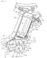
- Fig. 1 is a left side view of a motor-assisted bicycle according to one embodiment of the present invention is applied;
- Fig. 2 is a right side view showing an essential portion of the bicycle shown in Fig. 1;
- Fig. 3 is an enlarged view showing an essential portion of the bicycle shown in Fig. 1.
- a body frame 2 of a motor-assisted bicycle according to the present invention includes a head pipe 21 positioned on the front side of a body of the bicycle; a down pipe 22 extending rearwardly, downwardly from the head pipe 21; and a seat post 23 raised upwardly, rearwardly from a portion, near the lower end, of the down pipe 22.
- the seat post 23 is integrally connected to the down pipe 22, and accordingly, the body frame 2 is formed into a U-shape projecting downwardly as a whole. Since the seat post 23 extends upwardly, rearwardly from the connection portion with the down pipe 22 and the down pipe 22 extends forwardly, upwardly from the connection portion with the seat post 23, a gap between the seat post 23 and the down pipe 22 becomes larger toward the upper side from the connection portion therebetween. As a result, when getting on and off the bicycle, a rider is easy to stride across the U-shaped body frame 2.
- connection portion between the down pipe 22 and the seat post 23 and its neighborhood are covered with a resin cover 33.
- the resin cover 33 which is divided into upper and lower parts, is removably mounted.
- a handle post 27A is turnably inserted in the head pipe 21.
- a handlebar 27 is connected to an upper end of the handle post 27A, and a front fork 26 is connected to a lower end of the handle post 27A.
- the front fork 26 connected to the handle post 27A is steerable by the handlebar 27.
- a front wheel WF is rotatably supported by lower ends of the front fork 26.
- a motor-driven assist unit 1 including an electric motor for assisting leg-power is provided on a lower portion of the body frame 2.
- a power supply switch 29 for the motor-driven assist unit 1, which is turned on/off by a power supply key, is provided on a portion, near the head pipe 21, of the down pipe 22. It should be noted that the power supply switch 29 may be provided on the handlebar 27 in front of the handle post 27A.
- a crank shaft 101 is rotatably supported by the motor-driven assist unit 1, and pedals 12 are rotatably supported via cranks 11 by right and left ends of the crank shaft 101.
- a pair of right and left rear lower arms 25 extend rearwardly from the motor-driven assist unit 1, and a rear wheel WR as a drive wheel is rotatably supported between rear ends of the rear lower arms 25.
- a pair of right and left rear upper arms 24 are provided between an upper portion of the seat post 23 and lower ends of the rear lower arms 25.
- a seat pipe 31, on an upper end of which a seat 30 is provided, is slidably inserted in the seat post 23, so that the vertical position of the seat 30 can be adjusted by sliding the seat pipe 31 in the seat post 23.
- a battery housing case 5 (hereinafter, referred to as "housing case") for housing a battery 4 is mounted on the back side of the seat post 23 at a position under the seat 30.
- the battery 4 which contains a plurality of battery cells each having a size allowed to be housed in a battery case formed into an approximately rectangular parallelopiped shape, is disposed along the seat post 23 with its longitudinal direction taken nearly in the vertical direction.
- a handle 41 with its grip portion positioned on the right side of the vehicular body is mounted on an end portion (upper end in Fig. 1) of the battery 4 in the longitudinal direction.
- the handle 41 is turnably supported by the battery 4, and is normally withdrawn in a recess provided at a corner of the battery 4. Since a rider generally stands on the left side of the vehicular body, the grip portion of the handle 41 is positioned on the right side of the vehicular body with its rotational shaft (not shown) disposed at a central portion of the vehicular body. With this arrangement, it is easy for the rider to raise the handle 41. Further, to allow the rider to easily check the residual power of the battery 4 from the riding position, a battery residue meter 42 is provided at a position, offset leftwardly from the seat 30, of the battery 4.
- an operating lever 45 for locking/unlocking the battery 4 and a wheel lock device 100 are disposed behind the battery 4.
- the operating lever 45 is inserted in a side chamber 50 provided behind the battery housing case.
- the side chamber 50 has a size longer in the vertical direction and an approximately rectangular shape.
- An engagement hook 52 which is biased clockwise on a right side view by a torsion spring 51, is provided in a lower portion of the side chamber 50.
- the engagement hook 52 is engaged in a recess 47 provided in a lower portion of the battery 4, whereby the battery 4 is fixed in the housing case 5.
- the recess 47 is formed into an approximately V-shape. Since the lower portion of the battery 4 is fixed by the engagement hook 52, the housing state of the battery 4 is stably kept. That is to say, even if the vehicular body is vibrated, the battery 4 is not moved in both the vertical direction and lateral direction.
- the seat 30 provided on the upper portion of the seat post 23 can be turned forwardly, by the unlocking operation of a lever 65, up to a position at which the seat 30 does not interfere with the withdrawal of the battery 4.
- the engagement hook 52 is engaged in the recess 47, even if the seat 30 is turned forwardly, the battery 4 cannot be withdrawn upwardly.
- the operating lever 45 is usually biased upwardly by a spring (not shown) suspended between the operating lever 45 and a wall of the side chamber 50.
- a spring (not shown) suspended between the operating lever 45 and a wall of the side chamber 50.
- plus (+) and minus (-) output terminals (discharge contacts) provided on the bottom of the battery 4 are electrically, mechanically connected to a contact unit 60 screwed in a battery bracket 49 fixed, typically by welding, to the seat post 23. This connection is stable because of the dead weight of the battery 4 and the pressing by the engagement hook 52.
- the operating lever 45 is depressed so that the engagement hook 52 is pushed down by the tip of the operating lever 45.
- the engagement hook 52 thus pushed down by the tip of the operating lever 45 is turned counterclockwise in the figure against the biasing force of the spring 51.
- the engagement hook 52 is escaped from the recess 47.
- the engagement of the engagement hook 52 in the recess 47 is released.
- the battery 4 can be withdrawn upwardly.
- the handle 41 can be used for withdrawal of the battery 4.
- the turning center of the engagement hook 52 is located rearwardly, upwardly from the recess 47 of the battery 4, and accordingly, when the engagement hook 52 is turned, the battery 4 is pushed down by the engagement hook 52, and more specifically, the upward movement of the battery 4 is restricted by a force applied by the engagement hook 52 in the direction offset obliquely, upwardly from the withdrawal direction of the battery 4. This makes it possible to effectively apply the engagement force to the battery 4 in the withdrawal direction while reducing the rearwardly projecting amount of the engagement means.
- An upper portion of the battery housing case 5 is fixed, by means of a screw 39, to a bracket 40 fixed, typically by welding, to the rear upper arm 24.
- the wheel lock device 100 and a rear fender 34 are also fixed to the bracket 40 by means of screws 44a and 44b, respectively.
- a front end of the battery bracket 49 is welded to the seat post 23, and a rear end of the battery bracket 49 is bolted to both a front end of the rear lower arm 25 and a hanger portion 90 of the motor-driven assist unit 1.
- the motor-driven assist unit 1 has two hanger portions 91 and 92, in addition to the above hanger portion 90. These hanger portions 92, 91 and 90 of the motor-driven assist unit 1 are bolted to a rear end of the down pipe 22, a portion near the front end of the battery bracket 49, and the rear lower arm 25 near the rear end of the battery bracket 49, respectively. In this way, the motor-driven assist unit 1 is fixedly suspended from the body frame 2. It should be noted that since the hanger portion 92 is located under the crank shaft 101 of the motor-driven assist unit 1, the bottom, that is, the lowermost end of the U-shaped body frame 2 can be located under the crank shaft 101.
- the bottom of the U-shaped body frame 2 is located at the low level as described above, it is possible to improve the ease of the rider's striding motion across the body frame 2. Further, since the motor-driven assist unit 1 is supported at its low level hanger portion 92 by the lower end of the down pipe 22, that is, disposed at a lower level as a whole, it is possible to lower the center of gravity of the motor-driven assist unit 1.
- the motor-driven assist unit 1 contains the crank shaft 101, a first idle shaft 102, a second idle shaft 103, an output shaft 105 to which the drive sprocket 13 is connected, and gears 111, 102d, 102e, and 115 for transmitting power between the shafts 101, 102, 103, and 105.
- the electric motor M having a rotational shaft 104 disposed in parallel to the crank shaft 101 is mounted to the motor-driven assist unit 1.
- the reason why the rotational shaft 104 of the electric motor M is in parallel to the crank shaft 101 is to reduce a portion, projecting rearwardly from the motor-driven assist unit 1, of the electric motor M. This makes it possible to reduce a gap between the crank shaft 101 and the rear wheel WR and hence to avoid the wheel base from becoming longer.
- the battery 4 mounted on the battery bracket 49 located behind the seat post 23 supplies power to the motor M, and the motor M generates assist-power responding to leg-power detected by a leg-power detecting mechanism (to be described later) provided on the first idle shaft 102.
- the rotation of the motor M is transmitted to the first idle shaft 102 via the second idle shaft 103, and is synthesized with man-power (leg-power) on the first idle shaft 102.
- the resultant power is then transmitted to the output shaft 105.
- the whole of the drive sprocket 13 and an upper half of the chain 6 are covered with a chain cover 32. Since in this bicycle the drive sprocket 13 is not concentric with the crank shaft 101, it is not essential that the chain cover 32 has a circular-arc portion centered on the crank shaft 101; however, in order to obtain a good external appearance, prevent the catch of the rider's leg, protect the motor-driven assist unit 1, and ensure a conventional familiar image of a bicycle, the chain cover 32 is extended in a cylindrical shape centered on the crank shaft 101 up to a position to cover the whole of the drive sprocket 13.
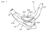
- Fig. 7 is a side view showing the connection portion (butt portion) between the down pipe 22 and the seat post 23.
- the cover 33 is shown by an imaginary line.
- the down pipe 22 is welded to the seat post 23 at the butt portion therebetween, and a cover mounting bracket 221 is welded to the welded portion.
- a power unit mounting bracket 222 is welded to an end portion of the down pipe 22.
- a hole 223 is matched to a bolt of the hanger portion 92.
- the down pipe 22 is more rigidly connected to the seat post 23 by means of these brackets 221 and 222.
- a nut 224 is welded to an upper portion of the bracket 221, and an upper cover 331 is connected to the bracket 221 by means of the nut 224 and a stop screw 225 associated with the nut 224.
- the upper cover 331 is mounted to the body frame 2 by connecting the upper cover 331 to the bracket 221 and assembling a lower cover 332 to the upper cover 331.
- the upper cover 331 is fixed to the body frame 2; however, the lower cover 332 may be fixed to the body frame 2 and the upper cover may be deformed to be fixed to the lower cover 332.
- Fig. 4 is a side view of the motor-driven assist unit 1, with parts partially cutaway;
- Fig. 5 is a sectional view, taken on line A-A of Fig. 4, showing gear trains; and
- Fig. 6 is a sectional view, taken on line B-B of Fig. 4, showing gear trains.
- a case 10 of the motor-driven assist unit 1 is formed by connecting a left half (left case) 10L and a right half (right case) 10R, each of which is made from aluminum, to each other by means of a plurality of bolts 781.
- each of bosses 771a, 771b, and 771c of the hanger portions 90, 91 and 92 has no parting plane, the left and right cases 10L and 10R can be separated from each other by removing the bolts 781 while the motor-driven assist unit 1 is left mounted on the body frame 2.
- the right case 10R can be removed while the left case 10L is left mounted on the body frame 2.
- the inside of the motor-driven assist unit 1 may be exposed by removing a cover 10A to be described later.
- the crank shaft 101 as a leg-power input shaft is rotatably supported by the case 10 via bearings 181 and 182.
- a large-diameter acceleration gear 111 is rotatably supported on the crank shaft 101 via a one-way clutch 161, and accordingly, even if the crank shaft 101 is reversely rotated, the acceleration gear 111 is not reversely rotated.
- the first idle shaft 102 including a leg-power (torque) detecting mechanism is rotatably supported by the case 10 at a position offset rearwardly, downwardly from the crank shaft 101.
- the first idle shaft 102 includes hollow-shaped first and second drive shafts 102a and 102b, which are separated from each other on the left and right sides and coaxially disposed in the transverse direction; and a torsion bar 102c passing through the drive shafts 102a and 102b, with both ends thereof spline-connected to the left end of the first drive shaft 102a and the right end of the second drive shaft 102b.
- a small-diameter gear teeth portion 113 formed on an small-diameter portion of the outer periphery of the first drive shaft 102a is meshed with the acceleration gear 111 of the crank shaft 101.
- the first drive shaft 102a is rotatably supported by the left case 10L of the case 10 via bearings 183a and 183b, and the second drive shaft 102b is rotatably supported by the right case 10R of the case 10 via a bearing 184.
- a first gear 102d is fixed to a small-diameter portion of the outer periphery of the second drive shaft 102b, and a second gear 102e is inserted on a large-diameter portion of the outer periphery of the second drive shaft 102b via a ratchet 162.
- the reason why the ratchet 162 is provided is as follows: namely, since the second gear 102e is connected to the motor M via a gear to be described later, it is required to cut off the connection between the first gear 102d and the second gear 102e in order not to apply a reverse rotational force to the motor M when the bicycle runs by man-power while the motor M is stopped.
- leg-power detecting mechanism provided on the first idle shaft 102
- positions of components of the mechanism when small-leg power is applied to the mechanism are shown on the right side from the shaft 102 in Fig. 5, and positions of the components of the mechanism when large leg-power is applied to the mechanism are shown on the left side from the shaft 102 in Fig. 5.
- a slider 921 is spline-connected to a large-diameter portion of the outer periphery of the first drive shaft 102a.
- a ball cup 924 is pushed to the second drive shaft 102b side via a washer by a coil spring 923 biased to the right side of the vehicular body. Further, the slider 921 is pushed to the second drive shaft 102b by the ball cup 924 in a state in which the rotation of the slider 921 is absorbed by the ball cup 924.
- a displacement detecting lever 152 supported by a pivot 153 is in contact with the left side of the washer of the coil spring 923.
- An end surface, facing to the first drive shaft 102a side, of a flange provided on an intermediate portion of the second drive shaft 102b has a plurality of (for example, two) cam grooves 922.
- the depth of the cam groove 922 is continuously changed along the circumferential direction.
- projecting cam portions 921a to be engaged in the cam grooves 922 are formed on an end surface, facing to the second drive shaft 102b, of the slider 921.
- the torsion bar 102c causes a rotational torsion in response to leg-power applied to the crank shaft 101, with a result that a differential phase (positional deviation in the rotational direction) occurs between the first and second drive shafts 102a and 102b.
- a differential phase positional deviation in the rotational direction
- an axial displacement of the displacement detecting lever 152 represents leg-power inputted to the crank shaft 101.
- the leg-power thus detected as the axial displacement by the leg-power detecting mechanism is converted into an electric signal by a stroke sensor 150 (see Fig. 6), which will be described in detail later, and is transmitted to the control unit 8.
- the second idle shaft 103 is rotatably supported by the case 10 via bearings 185 and 186 at a position offset rearwardly, downwardly from the first idle shaft 102.
- a gear teeth portion 114 to be meshed with the second gear 102e of the second drive shaft 102b is formed on the outer periphery of the second idle shaft 103, and a second intermediate gear 115 is fixed to an end portion of the second idle shaft 103.
- the electric motor M is disposed at a position offset rearwardly, downwardly from the second idle shaft 103, and the rotational shaft 104 thereof is rotatably supported by the case 10 via bearings 187 and 188.
- a motor housing 10M is mounted to the left case 10L by means of a bolt 782.
- An O-ring 10S is interposed between the motor housing 10M and the left case 10L.
- a stator rotor 131 including a motor coil 130 is fixed to the rotational shaft 104 of the motor M, and a magnet 132 is provided around the stator rotor 131.
- a gear teeth portion 116 to be meshed with the second intermediate gear 115 of the second idle shaft 103 is fixed to one end of the rotational shaft 104.
- the second intermediate gear 115 may be preferably made from a resin for suppressing gear noise occurring by meshing between the gear 116 rotated at a high speed and the second intermediate gear 115.
- the cover 10A which may be preferably made from a resin, is fastened to the left case 10L on the left sides of the gears 115 and 116 by means of a bolt 783, so that the noise reduction effect can be further enhanced.
- a water-proof seal 10B is provided along the entire periphery of a connection plane between the cover 10A and the left case 10L, and to further enhance the water-proof, a water-proof rib 10C is provided along the outer periphery of the connection plane between the resin cover 10A and the left case 10L. Accordingly, the water-proof between the cover 10A and the left case 10L can be sufficiently ensured even if the cover 10A is deformed when the cover 10A is fastened to the left case 10L by the bolt 783.
- a control unit 8 for controlling the motor-driven assist unit 1 is mounted at a position offset forwardly, downwardly from the crank shaft 101.
- the control unit 8 is configured such that a control circuit board 82 is contained in a resin made dish-like case 81 with a gap portion and the board surface molded with an insulating resin 83.
- Various control circuits 820, a plurality of power transistors (FETs) 821a, a plurality of diodes 821b, and a rotation sensor 822 are mounted on the control circuit board 82.
- the FETs and diodes, which cause heat generation upon operation thereof, are fixedly in area-contact with an aluminum made radiation plate 829.
- the radiation plate 829 is fixedly in area-contact with the right case 10R made from aluminum for enhancing the radiation effect.
- the rotation sensor 822 is fixed in the vicinity of an end of the control circuit board 82 in such a manner as to face to the outer periphery of the acceleration gear 111 of the crank shaft 101. Accordingly, the heat generated by the heat generating devices 821a and 821b is radiated to the right case 10R, and the rotation sensor 822 disposed in the vicinity of the left case 10L is not affected by the heat generated by the devices 821a and 821b.
- a partition wall 754 is provided in front of an inner wall portion 756, positioned inside the case 10, of a wall surface of the left case 10L covering the outer periphery of the motor M.
- a space surrounded by the partition wall 754 and the inner wall portion 756 forms a duct through which the lead wires 751 for connecting the control unit 8 to the motor M are guided.
- Motor side terminals 752 of the lead wires 751 are fixed to power supply parts which pass through the left case 10L at positions adjacent to the bearing 188.
- the lead wires 751 extending from the terminals 752 are introduced from the left case 10L side into the duct 753, and are withdrawn to the right case 10R side.
- the lead wires 751 thus withdrawn to the right case 10R side extend to the control unit 8 along the inner surface of the right case 10R.
- a clamp plate 755 is hung between a boss 749 for supporting the bearing 184 and a boss 748 for supporting the bearing 185.
- the lead wires 751 withdrawn from the duct 753 are certainly guided along the inner surface of the right case 10R while being restricted by the clamp plate 755.
- the lead wires 751 can be thus laid out from the motor M to the control unit 8 not by way of a space, on the left case 10L side, which are occupied with the gears 115 and 111, etc., but by way of a relatively free space on the right case 10R side. Further, the passage through which the lead wires 751 pass is clearly separated from the central portion of the case 10 in which the gears are collectively disposed, by the partition wall 754.
- the rotation sensor 822 is provided on the control unit 8 and the control unit 8 is disposed such that the rotation sensor 822 is disposed in the vicinity of the rotor (large-diameter gear 111) rotated in synchronization with the crank shaft 101, it is possible to eliminate the need of additionally providing a space for the rotation sensor 822 and hence to make compact the whole of the motor-assisted system. Further, since a distance between the rotation sensor 822 and the control unit 8 can be reduced, it is possible not only to eliminate the need of provision of a wiring cord therebetween but also to suppress the inclusion of noise in an output signal from the rotation sensor 822.
- control unit 8 Since the control unit 8 is disposed at the position offset forwardly, downwardly from the crank shaft 101 in the posture in which the motor-driven assist unit 1 is mounted to the body frame 2, it is possible to enhance an effect of air-cooling the control unit 8 upon running of the bicycle, and hence to improve the cooling efficiency of the control unit 8.
- a positioning pin 811 extending in parallel to a bottom surface of the dish-like case 81 projects outwardly from the bottom surface of the dish-like case 81 at a position corresponding to a rotation sensor mounting position of the control board 82, and a position hole 911 in which the position pin 811 is to be inserted is formed in a portion, facing to the positioning pin 811, of the case 10.
- a positioning pin 812 extending in parallel to a side surface of the dish-like case 81 projects outwardly from the side surface of the dish-like case 81 (see Fig. 4), and a positioning hole 912 in which the position pin 812 is to be inserted is formed in a portion, facing to the positioning pin 812, of the case 10. Accordingly, two planes of the control unit 8 can be positioned to keep a clearance between the rotation sensor 822 and the large-diameter gear 111 at a specific value.
- the dish-like case 81 of the control unit 8 is positioned relative to the case 10 such that when the positioning pins 811 and 812 first comes into contact with the entrances of the positioning holes 911 and 912, the rotation sensor 822 does not face to the large-diameter acceleration gear 111, and thereafter, when the pins 811 and 812 are started to be inserted in the holes 911 and 912, the relative positional relationship (facing relationship) between the gear teeth portion of the acceleration gear 111 and the rotation sensor 822 becomes a predetermined relationship.
- control unit 8 is fixed to the case 10 by fastening both side portions of an end portion, opposed to the end portion on which the rotation sensor 822 and the positioning pin 811 are provided, of the dish-like case 81, to the case 10 by means of screws 831 (831a and 831b, see Fig. 4).
- the positioning pins 811 and 812 as the positioning means are provided on the control unit 8 and the control unit 8 is fixed at the specific position in the motor-driven assist unit 1 with its specific posture kept, it is possible to keep the relative positional relationship between the rotation sensor 822 and the rotor (acceleration gear 111) at the predetermined relation, and hence to ensure the accuracy of detection of the rotational speed of the rotor.
- the output shaft 105 is located at a position offset rearwardly, upwardly from the first idle shaft 102, and is rotatably supported by the case 10 via bearings 191 and 192.
- a fourth gear 118 meshed with the first gear 102d of the second drive shaft 102b is provided on the output shaft 105, and the drive sprocket 13 is fixed to an end portion, exposed from the case 10, of the output shaft 105.
- leg-power as man-power is inputted to the crank shaft 101 via the pedals 12 and the cranks 11, and is transmitted from the first drive shaft 102a to the second drive shaft 102b of the first idle shaft 102 via the acceleration gear 111.
- rotational torque of the electric motor M is transmitted to the second drive shaft 102b via the gear 115, second idle shaft 103, gear teeth portion 114, and second gear 102e, and is synthesized with the leg-power on the second drive shaft 102b.
- the resultant power on the second drive shaft 102b is transmitted to the output shaft 105 via the first gear 102d and fourth gear 118, and is further transmitted to the rear wheel WR via the drive sprocket 13 and chain 6.
- a displacement detecting lever 152 with its one end swingably supported by a pin 153 is engaged with the ball cup 924 of the first idle shaft 102, and a stroke detecting shaft 151 of the stroke sensor 150 fixed to the right case 10R is connected to the other end of the displacement detecting lever 152.
- the ball cup 924 is axially displaced in accordance with the differential phase.
- the displacement detecting lever 152 is swung by the axial displacement of the ball cup 924, and the swing motion of the lever 152 is transmitted to the stroke sensor 150. In this way, the leg-power inputted to the crank shaft 101 is detected by the stroke sensor 150.
- the detected leg-power is converted into an electric signal, which is then supplied to the control unit 8.
- the control unit 8 determines most suitable assist torque on the basis of a rotational speed of the crank shaft (acceleration gear 111) detected by the rotation sensor 822 and the above-described leg-power, and controls, by the power transistors 821a, a drive current to be supplied to the electric motor M at such a value as to allow the electric motor M to generate the above assist-power.
- the leg-power detecting mechanism for converting leg-power inputted to the crank shaft 101 into a mechanical displacement is provided on the first idle shaft 102 adjacent to the crank shaft 101, it is possible to eliminate the need of provision of a space which is required if the leg-power detecting mechanism is provided independently from the first idle shaft 102, and hence to ensure a space required for disposing the control unit 8 in the case 10 of the motor-driven assist unit 1 without enlargement of the case 10 of the motor-driven assist unit 1.
- a motor-assisted bicycle on which a motor-driven assist unit 1 including a crank shaft 101 and a motor for generating assist-power to be imparted to the crank shaft 101 is mounted, has a downwardly projecting U-shaped body frame 2 connected to a head pipe 21.
- the motor is positioned rearwardly from the crank shaft 101; and the bottom of the U-shaped body frame 2 is positioned forwardly from the unit 1 and is also positioned under the crank shaft 101.
- the bottom that is, the lowermost portion of the U-shaped body frame 2 can be lowered, the position of the obstacle to the rider's motion to get on and off the bicycle becomes lower, with a result that it is easy for the rider to stride across the U-shaped body frame, thereby improving the usability of the bicycle when the rider gets on and off the bicycle.
Landscapes
- Engineering & Computer Science (AREA)
- Chemical & Material Sciences (AREA)
- Combustion & Propulsion (AREA)
- Transportation (AREA)
- Mechanical Engineering (AREA)
- Automatic Cycles, And Cycles In General (AREA)
- Electric Propulsion And Braking For Vehicles (AREA)
- Arrangement Or Mounting Of Propulsion Units For Vehicles (AREA)
Abstract
Description
- The present invention relates to a motor-assisted bicycle, and particularly to a motor-assisted bicycle having a frame structure allowing a rider to easily get on and off the bicycle.
- Fig. 8 is a side view showing one example of a motor-assisted bicycle including a drive system using leg-power and a drive system using power of an electric motor. Referring to Fig. 8, a power unit 1a for assisting the drive system using leg-power synthesizes a drive force outputted from an electric motor "m" with a drive force manually inputted from pedals 12a, and transmits the resultant power to a rear wheel WR via a crank shaft 101a. The motor "m" and the power unit 1a are disposed in front of the crank shaft 101a and are suspended from a main tube, that is, a down pipe 22a. A controller CT is also suspended from the down pipe 22a. The motor-assisted bicycle having such a structure has been described, for example, in Japanese Patent Laid-open No. Hei 8-142961.
- The above-described prior art bicycle, however, has a problem that since the power unit is suspended from the down pipe and the motor projects forwardly, the height of the down pipe from the ground must be larger, with a result that it is not easy for a rider to stride across the down pipe when the rider gets on and off the bicycle and further the center of gravity of the bicycle is higher. In particular, since the motor having a relatively large weight is located over the crank shaft, the center of gravity is further higher.
- An object of the present invention is to provide a motor-assisted bicycle allowing a rider to easily get on and off the bicycle and capable of lowering the center of gravity of the bicycle thereby improving the running stability.
- To achieve the above object, according to a first feature of the present invention, there is provided a motor-assisted bicycle on which a motor-driven assist unit including a crank shaft and a motor for generating assist-power to be imparted to the crank shaft is mounted, characterized in that the motor-assisted bicycle includes: a downwardly projecting U-shaped body frame connected to a head pipe for supporting a handlebar; wherein the motor is positioned rearwardly from the crank shaft; and the lowermost position of the U-shaped body frame is positioned forwardly from the motor-driven assist unit and is also positioned under the crank shaft.
- With this first feature, since the motor is disposed behind the crank shaft and thereby no member projects forwardly from the motor-driven assist unit and further the lowermost portion of the U-shaped body frame is positioned lower than the crank shaft, the position of the obstacle to the rider's motion to get on and off the bicycle becomes lower, with a result that it is easy for the rider to stride across the U-shaped body frame, thereby improving the usability of the bicycle when the rider gets on and off the bicycle.
- According to a second feature of the present invention, the motor is disposed with its shaft kept in parallel to the crank shaft. With this second feature, since a portion, projecting rearwardly, of the motor positioned behind the crank shaft is reduced, it is possible to suppress the extension of a wheel base while ensuring the ease of the rider's striding motion across the U-shaped body frame.
- According to a third feature of the present invention, the motor-driven assist unit is connected to the U-shaped body frame, and the connection portion is offset downwardly, forwardly from the crank shaft. With this third feature, since the motor-driven assist unit is supported by a lower portion of the vehicular body, it is possible to lower the center of gravity of the bicycle, and make the U-shaped body frame extend to a position being as low as possible and hence to further improve the ease of the rider's striding motion across the U-shaped body frame.
- According to a fourth feature of the present invention, the body frame is formed by connecting a down pipe extending downwardly, rearwardly from the head pipe to a seat post extending upwardly, rearwardly from a portion of the down pipe, the portion being near a lower end of the down pipe and positioned in front of the crank shaft. With this fourth feature, since the body frame can be formed by connecting the two members to each other, the connection position between the two members can be lowered to a point at which the two members are sharply tilted, with a result that it is possible to enhance the ease of the rider's striding motion across the U-shaped body frame and to improve the productivity in production of the body frame as compared with the production of the body frame by bending one member to form a down pipe portion and a seat post portion. Further, since the opening of the U-shaped body frame becomes wider toward the upper side, it is easy for the rider to stride across the U-shaped body frame.
- According to a fifth feature of the present invention, a battery as a power supply of the motor-driven assist unit is mounted at a position adjacent to the back surface of the seat post. With this fifth feature, since the battery is not present in a space in which the rider strides across the body frame, it is easy for the rider to stride across the body frame, and further since the battery is disposed near the central portion of the body frame, it is possible to keep a good balance of the center of gravity of the bicycle and to facilitate the wiring for supplying a current to the motor-driven assist unit.
- According to a sixth feature of the present invention, a controller for controlling the motor-driven assist unit is disposed in the motor-driven assist unit at a position offset downwardly, forwardly from the crank shaft. With this sixth feature, since the controller is disposed at a lower position, it is possible not only to further lower the center of gravity of the bicycle in combination of the above-described configurations, but also to realize the layout of the controller by making effective use of a dead space while making the unit as close to the batter as possible thereby lowering the center of gravity and well as concentrating the mass of the bicycle.
- According to the invention described in claim 1, since the motor is disposed behind the crank shaft and thereby no member projects forwardly from the motor-driven assist unit and further the lowermost portion of the U-shaped body frame is positioned lower than the crank shaft, the position of the obstacle to the rider's motion to get on and off the bicycle becomes lower, with a result that it is easy for the rider to stride across the U-shaped body frame, thereby improving the usability of the bicycle when the rider gets on and off the bicycle.
- According to the invention described in
claim 2, since a portion, projecting rearwardly, of the motor positioned behind the crank shaft is reduced, it is possible to suppress the extension of a wheel base while ensuring the ease of the rider's striding motion across the U-shaped body frame. - According to the invention described in
claim 3, since the motor-driven assist unit is supported by a lower portion of the vehicular body, it is possible to lower the center of gravity of the bicycle, and make the U-shaped body frame extend to a position being as low as possible and hence to further improve the ease of the rider's striding motion across the U-shaped body frame. - According to the invention described in claim 4, since the body frame can be formed by connecting the two members to each other, the connection position between the two members can be lowered to a point at which the two members are sharply tilted, with a result that it is possible to enhance the ease of the rider's striding motion across the U-shaped body frame and to improve the productivity in production of the body frame as compared with the production of the body frame by bending one member to form a down pipe portion and a seat post portion. Further, since the opening of the U-shaped body frame becomes wider toward the upper side, it is easy for the rider to stride across the U-shaped body frame.
- According to the invention described in
claim 5, since the battery is not present in a space in which the rider strides across the body frame, it is easy for the rider to stride across the body frame, and further since the battery is disposed near the central portion of the body frame, it is possible to keep a good balance of the center of gravity of the bicycle and to facilitate the wiring for supplying a current to the motor-driven assist unit. - According to the invention described in
claim 6, since the controller is disposed at a lower position, it is possible not only to further lower the center of gravity of the bicycle in combination of the above-described configurations, but also to realize the layout of the controller by making effective use of a dead space while making the unit as close to the batter as possible thereby lowering the center of gravity and well as concentrating the mass of the bicycle. - Hereinafter, the present invention will be described in detail with reference to the drawings.
- It is illustrated in:
- Fig. 1: A left side view of a motor-assisted bicycle according to one embodiment of the present invention.
- Fig. 2: A right side view showing an essential portion of the motor-assisted bicycle according to the embodiment of the present invention.
- Fig. 3: An enlarged view of an essential portion of the motor-assisted bicycle according to the embodiment of the present invention.
- Fig. 4: A sectional view of a motor-driven assist unit.
- Fig. 5: A sectional view taken on line A-A of Fig. 4.
- Fig. 6: A sectional view taken on line B-B of Fig. 4.
- Fig. 7: A side view showing an essential portion of a body frame.
- Fig. 8: A left side view of a prior art motor-assisted bicycle.
-
- Fig. 1 is a left side view of a motor-assisted bicycle according to one embodiment of the present invention is applied; Fig. 2 is a right side view showing an essential portion of the bicycle shown in Fig. 1; and Fig. 3 is an enlarged view showing an essential portion of the bicycle shown in Fig. 1. Referring to Fig. 1, a
body frame 2 of a motor-assisted bicycle according to the present invention includes ahead pipe 21 positioned on the front side of a body of the bicycle; adown pipe 22 extending rearwardly, downwardly from thehead pipe 21; and a seat post 23 raised upwardly, rearwardly from a portion, near the lower end, of thedown pipe 22. Theseat post 23 is integrally connected to thedown pipe 22, and accordingly, thebody frame 2 is formed into a U-shape projecting downwardly as a whole. Since theseat post 23 extends upwardly, rearwardly from the connection portion with thedown pipe 22 and thedown pipe 22 extends forwardly, upwardly from the connection portion with theseat post 23, a gap between theseat post 23 and thedown pipe 22 becomes larger toward the upper side from the connection portion therebetween. As a result, when getting on and off the bicycle, a rider is easy to stride across the U-shapedbody frame 2. - The connection portion between the
down pipe 22 and theseat post 23 and its neighborhood are covered with aresin cover 33. Theresin cover 33, which is divided into upper and lower parts, is removably mounted. Ahandle post 27A is turnably inserted in thehead pipe 21. Ahandlebar 27 is connected to an upper end of thehandle post 27A, and afront fork 26 is connected to a lower end of thehandle post 27A. Thefront fork 26 connected to thehandle post 27A is steerable by thehandlebar 27. A front wheel WF is rotatably supported by lower ends of thefront fork 26. - A motor-driven assist unit 1 including an electric motor for assisting leg-power is provided on a lower portion of the
body frame 2. Apower supply switch 29 for the motor-driven assist unit 1, which is turned on/off by a power supply key, is provided on a portion, near thehead pipe 21, of thedown pipe 22. It should be noted that thepower supply switch 29 may be provided on thehandlebar 27 in front of thehandle post 27A. - A
crank shaft 101 is rotatably supported by the motor-driven assist unit 1, andpedals 12 are rotatably supported viacranks 11 by right and left ends of thecrank shaft 101. A pair of right and left rearlower arms 25 extend rearwardly from the motor-driven assist unit 1, and a rear wheel WR as a drive wheel is rotatably supported between rear ends of the rearlower arms 25. A pair of right and left rearupper arms 24 are provided between an upper portion of theseat post 23 and lower ends of the rearlower arms 25. Aseat pipe 31, on an upper end of which aseat 30 is provided, is slidably inserted in theseat post 23, so that the vertical position of theseat 30 can be adjusted by sliding theseat pipe 31 in theseat post 23. - A battery housing case 5 (hereinafter, referred to as "housing case") for housing a battery 4 is mounted on the back side of the
seat post 23 at a position under theseat 30. The battery 4, which contains a plurality of battery cells each having a size allowed to be housed in a battery case formed into an approximately rectangular parallelopiped shape, is disposed along theseat post 23 with its longitudinal direction taken nearly in the vertical direction. - A
handle 41 with its grip portion positioned on the right side of the vehicular body is mounted on an end portion (upper end in Fig. 1) of the battery 4 in the longitudinal direction. Thehandle 41 is turnably supported by the battery 4, and is normally withdrawn in a recess provided at a corner of the battery 4. Since a rider generally stands on the left side of the vehicular body, the grip portion of thehandle 41 is positioned on the right side of the vehicular body with its rotational shaft (not shown) disposed at a central portion of the vehicular body. With this arrangement, it is easy for the rider to raise thehandle 41. Further, to allow the rider to easily check the residual power of the battery 4 from the riding position, abattery residue meter 42 is provided at a position, offset leftwardly from theseat 30, of the battery 4. - Referring to Fig. 3, an operating
lever 45 for locking/unlocking the battery 4 and awheel lock device 100 are disposed behind the battery 4. The operatinglever 45 is inserted in aside chamber 50 provided behind the battery housing case. Theside chamber 50 has a size longer in the vertical direction and an approximately rectangular shape. Anengagement hook 52, which is biased clockwise on a right side view by atorsion spring 51, is provided in a lower portion of theside chamber 50. When the battery 4 is inserted in thehousing case 5, theengagement hook 52 is engaged in a recess 47 provided in a lower portion of the battery 4, whereby the battery 4 is fixed in thehousing case 5. The recess 47 is formed into an approximately V-shape. Since the lower portion of the battery 4 is fixed by theengagement hook 52, the housing state of the battery 4 is stably kept. That is to say, even if the vehicular body is vibrated, the battery 4 is not moved in both the vertical direction and lateral direction. - The
seat 30 provided on the upper portion of theseat post 23 can be turned forwardly, by the unlocking operation of alever 65, up to a position at which theseat 30 does not interfere with the withdrawal of the battery 4. However, in the state in which theengagement hook 52 is engaged in the recess 47, even if theseat 30 is turned forwardly, the battery 4 cannot be withdrawn upwardly. - The operating
lever 45 is usually biased upwardly by a spring (not shown) suspended between the operatinglever 45 and a wall of theside chamber 50. In the case of mounting the charged battery 4 to the bicycle, theseat 30 is turned forwardly, and the battery 4 is inserted from above into thehousing case 5. When the battery 4 is almost inserted in thehousing case 5, the lower end of the battery 4 is brought into contact with a side portion of theengagement hook 52 to push theengagement hook 52 counterclockwise. Then, when the battery 4 is further inserted in thehousing case 5, theengagement hook 52 is elastically engaged in the V-shaped recess 47 formed in the battery 4, whereby the battery 4 is fixed in thehousing case 5. At the same time, plus (+) and minus (-) output terminals (discharge contacts) provided on the bottom of the battery 4 are electrically, mechanically connected to acontact unit 60 screwed in abattery bracket 49 fixed, typically by welding, to theseat post 23. This connection is stable because of the dead weight of the battery 4 and the pressing by theengagement hook 52. - In the case of removing the battery 4, the operating
lever 45 is depressed so that theengagement hook 52 is pushed down by the tip of the operatinglever 45. Theengagement hook 52 thus pushed down by the tip of the operatinglever 45 is turned counterclockwise in the figure against the biasing force of thespring 51. As a result, theengagement hook 52 is escaped from the recess 47. In this way, the engagement of theengagement hook 52 in the recess 47 is released. After the engagement of theengagement hook 52 in the recess 47 is released, the battery 4 can be withdrawn upwardly. Thehandle 41 can be used for withdrawal of the battery 4. - In the means for locking the battery 4, the turning center of the
engagement hook 52 is located rearwardly, upwardly from the recess 47 of the battery 4, and accordingly, when theengagement hook 52 is turned, the battery 4 is pushed down by theengagement hook 52, and more specifically, the upward movement of the battery 4 is restricted by a force applied by theengagement hook 52 in the direction offset obliquely, upwardly from the withdrawal direction of the battery 4. This makes it possible to effectively apply the engagement force to the battery 4 in the withdrawal direction while reducing the rearwardly projecting amount of the engagement means. - An upper portion of the
battery housing case 5 is fixed, by means of ascrew 39, to abracket 40 fixed, typically by welding, to the rearupper arm 24. Thewheel lock device 100 and arear fender 34 are also fixed to thebracket 40 by means of screws 44a and 44b, respectively. - A front end of the
battery bracket 49 is welded to theseat post 23, and a rear end of thebattery bracket 49 is bolted to both a front end of the rearlower arm 25 and ahanger portion 90 of the motor-driven assist unit 1. The motor-driven assist unit 1 has twohanger portions above hanger portion 90. Thesehanger portions down pipe 22, a portion near the front end of thebattery bracket 49, and the rearlower arm 25 near the rear end of thebattery bracket 49, respectively. In this way, the motor-driven assist unit 1 is fixedly suspended from thebody frame 2. It should be noted that since thehanger portion 92 is located under thecrank shaft 101 of the motor-driven assist unit 1, the bottom, that is, the lowermost end of theU-shaped body frame 2 can be located under thecrank shaft 101. - Since the bottom of the
U-shaped body frame 2 is located at the low level as described above, it is possible to improve the ease of the rider's striding motion across thebody frame 2. Further, since the motor-driven assist unit 1 is supported at its lowlevel hanger portion 92 by the lower end of thedown pipe 22, that is, disposed at a lower level as a whole, it is possible to lower the center of gravity of the motor-driven assist unit 1. - The motor-driven assist unit 1 contains the
crank shaft 101, a firstidle shaft 102, a secondidle shaft 103, anoutput shaft 105 to which thedrive sprocket 13 is connected, and gears 111, 102d, 102e, and 115 for transmitting power between theshafts rotational shaft 104 disposed in parallel to the crankshaft 101 is mounted to the motor-driven assist unit 1. The reason why therotational shaft 104 of the electric motor M is in parallel to the crankshaft 101 is to reduce a portion, projecting rearwardly from the motor-driven assist unit 1, of the electric motor M. This makes it possible to reduce a gap between thecrank shaft 101 and the rear wheel WR and hence to avoid the wheel base from becoming longer. - Leg-power inputted from the
crank shaft 101 is acceleratedly transmitted to the firstidle shaft 102 and is transmitted from the firstidle shaft 102 to theoutput shaft 105, to rotate thedrive sprocket 13. The rotation of thedrive sprocket 13 is transmitted to awheel sprocket 14 of the rear wheel WR (see Fig. 1) via achain 6. The structure of the motor-driven assist unit 1 will be described in more detail with reference to Figs. 4, 5 and 6. - The battery 4 mounted on the
battery bracket 49 located behind theseat post 23 supplies power to the motor M, and the motor M generates assist-power responding to leg-power detected by a leg-power detecting mechanism (to be described later) provided on the firstidle shaft 102. The rotation of the motor M is transmitted to the firstidle shaft 102 via the secondidle shaft 103, and is synthesized with man-power (leg-power) on the firstidle shaft 102. The resultant power is then transmitted to theoutput shaft 105. - As shown in Figs. 1 and 2, the whole of the
drive sprocket 13 and an upper half of thechain 6 are covered with achain cover 32. Since in this bicycle thedrive sprocket 13 is not concentric with thecrank shaft 101, it is not essential that thechain cover 32 has a circular-arc portion centered on thecrank shaft 101; however, in order to obtain a good external appearance, prevent the catch of the rider's leg, protect the motor-driven assist unit 1, and ensure a conventional familiar image of a bicycle, thechain cover 32 is extended in a cylindrical shape centered on thecrank shaft 101 up to a position to cover the whole of thedrive sprocket 13. - The mounting of the
cover 33 on thebody frame 2 will be described. Fig. 7 is a side view showing the connection portion (butt portion) between thedown pipe 22 and theseat post 23. In this figure, thecover 33 is shown by an imaginary line. Referring to Fig. 7, thedown pipe 22 is welded to theseat post 23 at the butt portion therebetween, and acover mounting bracket 221 is welded to the welded portion. Further, a powerunit mounting bracket 222 is welded to an end portion of thedown pipe 22. Ahole 223 is matched to a bolt of thehanger portion 92. The downpipe 22 is more rigidly connected to theseat post 23 by means of thesebrackets - A
nut 224 is welded to an upper portion of thebracket 221, and anupper cover 331 is connected to thebracket 221 by means of thenut 224 and astop screw 225 associated with thenut 224. In this way, theupper cover 331 is mounted to thebody frame 2 by connecting theupper cover 331 to thebracket 221 and assembling alower cover 332 to theupper cover 331. - In the above-described example, the
upper cover 331 is fixed to thebody frame 2; however, thelower cover 332 may be fixed to thebody frame 2 and the upper cover may be deformed to be fixed to thelower cover 332. - The motor-driven assist unit 1 will be described in more detail below. Fig. 4 is a side view of the motor-driven assist unit 1, with parts partially cutaway; Fig. 5 is a sectional view, taken on line A-A of Fig. 4, showing gear trains; and Fig. 6 is a sectional view, taken on line B-B of Fig. 4, showing gear trains.
- Referring to Figs. 4 and 5, a
case 10 of the motor-driven assist unit 1 is formed by connecting a left half (left case) 10L and a right half (right case) 10R, each of which is made from aluminum, to each other by means of a plurality ofbolts 781. - Since each of
bosses hanger portions right cases bolts 781 while the motor-driven assist unit 1 is left mounted on thebody frame 2. To be more specific, theright case 10R can be removed while theleft case 10L is left mounted on thebody frame 2. As a result, it is possible to easily perform the maintenance of a control unit (controller) 8 and the motor M contained in thecase 10 of the motor-driven assist unit 1. In addition, to perform the maintenance of a portion, on theleft case 10L side, of the motor M and its drive system, the inside of the motor-driven assist unit 1 may be exposed by removing acover 10A to be described later. - The
crank shaft 101 as a leg-power input shaft is rotatably supported by thecase 10 viabearings diameter acceleration gear 111 is rotatably supported on thecrank shaft 101 via a one-way clutch 161, and accordingly, even if thecrank shaft 101 is reversely rotated, theacceleration gear 111 is not reversely rotated. The firstidle shaft 102 including a leg-power (torque) detecting mechanism is rotatably supported by thecase 10 at a position offset rearwardly, downwardly from thecrank shaft 101. - The first
idle shaft 102 includes hollow-shaped first andsecond drive shafts torsion bar 102c passing through thedrive shafts first drive shaft 102a and the right end of thesecond drive shaft 102b. A small-diametergear teeth portion 113 formed on an small-diameter portion of the outer periphery of thefirst drive shaft 102a is meshed with theacceleration gear 111 of thecrank shaft 101. Thefirst drive shaft 102a is rotatably supported by theleft case 10L of thecase 10 viabearings second drive shaft 102b is rotatably supported by theright case 10R of thecase 10 via abearing 184. - With this configuration, since leg-power inputted to the crank
shaft 101 is accelerated by theacceleration gear 111, the torque of the leg-power is reduced, with a result that torque applied to thetorsion bar 102c is reduced. This makes it possible to miniaturize thetorsion bar 102c, and hence to make compact the leg-power detecting mechanism as a whole. - A
first gear 102d is fixed to a small-diameter portion of the outer periphery of thesecond drive shaft 102b, and asecond gear 102e is inserted on a large-diameter portion of the outer periphery of thesecond drive shaft 102b via aratchet 162. The reason why theratchet 162 is provided is as follows: namely, since thesecond gear 102e is connected to the motor M via a gear to be described later, it is required to cut off the connection between thefirst gear 102d and thesecond gear 102e in order not to apply a reverse rotational force to the motor M when the bicycle runs by man-power while the motor M is stopped. - The mechanism for detection of leg-power will be described below. Additionally, with respect to the leg-power detecting mechanism provided on the first
idle shaft 102, positions of components of the mechanism when small-leg power is applied to the mechanism are shown on the right side from theshaft 102 in Fig. 5, and positions of the components of the mechanism when large leg-power is applied to the mechanism are shown on the left side from theshaft 102 in Fig. 5. - A
slider 921 is spline-connected to a large-diameter portion of the outer periphery of thefirst drive shaft 102a. Aball cup 924 is pushed to thesecond drive shaft 102b side via a washer by acoil spring 923 biased to the right side of the vehicular body. Further, theslider 921 is pushed to thesecond drive shaft 102b by theball cup 924 in a state in which the rotation of theslider 921 is absorbed by theball cup 924. Adisplacement detecting lever 152 supported by apivot 153 is in contact with the left side of the washer of thecoil spring 923. - An end surface, facing to the
first drive shaft 102a side, of a flange provided on an intermediate portion of thesecond drive shaft 102b has a plurality of (for example, two)cam grooves 922. The depth of thecam groove 922 is continuously changed along the circumferential direction. On the other hand, projectingcam portions 921a to be engaged in thecam grooves 922 are formed on an end surface, facing to thesecond drive shaft 102b, of theslider 921. - The
torsion bar 102c causes a rotational torsion in response to leg-power applied to the crankshaft 101, with a result that a differential phase (positional deviation in the rotational direction) occurs between the first andsecond drive shafts cam portion 921a and the corresponding recessedgroove 922 is changed on the basis of the differential phase, theslider 921 is slid, by the cam effect, leftwardly on thefirst drive shaft 102a against the elastic force of thecoil spring 923, and correspondingly thedisplacement detecting lever 152 is displaced. - Accordingly, an axial displacement of the
displacement detecting lever 152 represents leg-power inputted to the crankshaft 101. The leg-power thus detected as the axial displacement by the leg-power detecting mechanism is converted into an electric signal by a stroke sensor 150 (see Fig. 6), which will be described in detail later, and is transmitted to thecontrol unit 8. - The second
idle shaft 103 is rotatably supported by thecase 10 viabearings idle shaft 102. Agear teeth portion 114 to be meshed with thesecond gear 102e of thesecond drive shaft 102b is formed on the outer periphery of the secondidle shaft 103, and a secondintermediate gear 115 is fixed to an end portion of the secondidle shaft 103. - The electric motor M is disposed at a position offset rearwardly, downwardly from the second
idle shaft 103, and therotational shaft 104 thereof is rotatably supported by thecase 10 viabearings motor housing 10M is mounted to theleft case 10L by means of abolt 782. An O-ring 10S is interposed between themotor housing 10M and theleft case 10L. - A
stator rotor 131 including amotor coil 130 is fixed to therotational shaft 104 of the motor M, and amagnet 132 is provided around thestator rotor 131. Agear teeth portion 116 to be meshed with the secondintermediate gear 115 of the secondidle shaft 103 is fixed to one end of therotational shaft 104. The secondintermediate gear 115 may be preferably made from a resin for suppressing gear noise occurring by meshing between thegear 116 rotated at a high speed and the secondintermediate gear 115. Thecover 10A, which may be preferably made from a resin, is fastened to theleft case 10L on the left sides of thegears bolt 783, so that the noise reduction effect can be further enhanced. - A water-proof seal 10B is provided along the entire periphery of a connection plane between the
cover 10A and theleft case 10L, and to further enhance the water-proof, a water-proof rib 10C is provided along the outer periphery of the connection plane between theresin cover 10A and theleft case 10L. Accordingly, the water-proof between thecover 10A and theleft case 10L can be sufficiently ensured even if thecover 10A is deformed when thecover 10A is fastened to theleft case 10L by thebolt 783. - In the
case 10, as shown in Fig. 5, acontrol unit 8 for controlling the motor-driven assist unit 1 is mounted at a position offset forwardly, downwardly from thecrank shaft 101. Thecontrol unit 8 is configured such that acontrol circuit board 82 is contained in a resin made dish-like case 81 with a gap portion and the board surface molded with an insulatingresin 83.Various control circuits 820, a plurality of power transistors (FETs) 821a, a plurality of diodes 821b, and arotation sensor 822 are mounted on thecontrol circuit board 82. The FETs and diodes, which cause heat generation upon operation thereof, are fixedly in area-contact with an aluminum maderadiation plate 829. Theradiation plate 829 is fixedly in area-contact with theright case 10R made from aluminum for enhancing the radiation effect. Therotation sensor 822 is fixed in the vicinity of an end of thecontrol circuit board 82 in such a manner as to face to the outer periphery of theacceleration gear 111 of thecrank shaft 101. Accordingly, the heat generated by theheat generating devices 821a and 821b is radiated to theright case 10R, and therotation sensor 822 disposed in the vicinity of theleft case 10L is not affected by the heat generated by thedevices 821a and 821b. - Two
lead wires 751 for supplying power from thecontrol unit 8 to the motor M is laid out in thecase 10 as follows. Apartition wall 754 is provided in front of aninner wall portion 756, positioned inside thecase 10, of a wall surface of theleft case 10L covering the outer periphery of the motor M. A space surrounded by thepartition wall 754 and theinner wall portion 756 forms a duct through which thelead wires 751 for connecting thecontrol unit 8 to the motor M are guided. -
Motor side terminals 752 of thelead wires 751 are fixed to power supply parts which pass through theleft case 10L at positions adjacent to thebearing 188. Thelead wires 751 extending from theterminals 752 are introduced from theleft case 10L side into theduct 753, and are withdrawn to theright case 10R side. Thelead wires 751 thus withdrawn to theright case 10R side extend to thecontrol unit 8 along the inner surface of theright case 10R. Aclamp plate 755 is hung between aboss 749 for supporting thebearing 184 and aboss 748 for supporting thebearing 185. Thelead wires 751 withdrawn from theduct 753 are certainly guided along the inner surface of theright case 10R while being restricted by theclamp plate 755. - The
lead wires 751 can be thus laid out from the motor M to thecontrol unit 8 not by way of a space, on theleft case 10L side, which are occupied with thegears right case 10R side. Further, the passage through which thelead wires 751 pass is clearly separated from the central portion of thecase 10 in which the gears are collectively disposed, by thepartition wall 754. - In this way, according to this embodiment, since the
rotation sensor 822 is provided on thecontrol unit 8 and thecontrol unit 8 is disposed such that therotation sensor 822 is disposed in the vicinity of the rotor (large-diameter gear 111) rotated in synchronization with thecrank shaft 101, it is possible to eliminate the need of additionally providing a space for therotation sensor 822 and hence to make compact the whole of the motor-assisted system. Further, since a distance between therotation sensor 822 and thecontrol unit 8 can be reduced, it is possible not only to eliminate the need of provision of a wiring cord therebetween but also to suppress the inclusion of noise in an output signal from therotation sensor 822. - Since the
control unit 8 is disposed at the position offset forwardly, downwardly from thecrank shaft 101 in the posture in which the motor-driven assist unit 1 is mounted to thebody frame 2, it is possible to enhance an effect of air-cooling thecontrol unit 8 upon running of the bicycle, and hence to improve the cooling efficiency of thecontrol unit 8. - A
positioning pin 811 extending in parallel to a bottom surface of the dish-like case 81 projects outwardly from the bottom surface of the dish-like case 81 at a position corresponding to a rotation sensor mounting position of thecontrol board 82, and aposition hole 911 in which theposition pin 811 is to be inserted is formed in a portion, facing to thepositioning pin 811, of thecase 10. Similarly, apositioning pin 812 extending in parallel to a side surface of the dish-like case 81 projects outwardly from the side surface of the dish-like case 81 (see Fig. 4), and apositioning hole 912 in which theposition pin 812 is to be inserted is formed in a portion, facing to thepositioning pin 812, of thecase 10. Accordingly, two planes of thecontrol unit 8 can be positioned to keep a clearance between therotation sensor 822 and the large-diameter gear 111 at a specific value. - The dish-
like case 81 of thecontrol unit 8 is positioned relative to thecase 10 such that when the positioning pins 811 and 812 first comes into contact with the entrances of the positioning holes 911 and 912, therotation sensor 822 does not face to the large-diameter acceleration gear 111, and thereafter, when thepins holes acceleration gear 111 and therotation sensor 822 becomes a predetermined relationship. - As shown in Fig. 5, the
control unit 8 is fixed to thecase 10 by fastening both side portions of an end portion, opposed to the end portion on which therotation sensor 822 and thepositioning pin 811 are provided, of the dish-like case 81, to thecase 10 by means of screws 831 (831a and 831b, see Fig. 4). - In this way, according to this embodiment, since the positioning pins 811 and 812 as the positioning means are provided on the
control unit 8 and thecontrol unit 8 is fixed at the specific position in the motor-driven assist unit 1 with its specific posture kept, it is possible to keep the relative positional relationship between therotation sensor 822 and the rotor (acceleration gear 111) at the predetermined relation, and hence to ensure the accuracy of detection of the rotational speed of the rotor. - Further, according to this embodiment, since one side portion of the
control unit 8 is engaged with thecase 10 of the motor-driven assist unit 1 by the positioning means provided on the one side portion of thecontrol unit 8 and the other side portion of thecontrol unit 8 is fastened to thecase 10 by the fastening means, it is possible to simplify the fastening structure and to reduce the number of parts. - On the other hand, as shown in Figs. 4 and 6, the
output shaft 105 is located at a position offset rearwardly, upwardly from the firstidle shaft 102, and is rotatably supported by thecase 10 viabearings fourth gear 118 meshed with thefirst gear 102d of thesecond drive shaft 102b is provided on theoutput shaft 105, and thedrive sprocket 13 is fixed to an end portion, exposed from thecase 10, of theoutput shaft 105. - According to the motor-driven assist unit configured as described above, leg-power as man-power is inputted to the crank
shaft 101 via thepedals 12 and thecranks 11, and is transmitted from thefirst drive shaft 102a to thesecond drive shaft 102b of the firstidle shaft 102 via theacceleration gear 111. On the other hand, rotational torque of the electric motor M is transmitted to thesecond drive shaft 102b via thegear 115, secondidle shaft 103,gear teeth portion 114, andsecond gear 102e, and is synthesized with the leg-power on thesecond drive shaft 102b. The resultant power on thesecond drive shaft 102b is transmitted to theoutput shaft 105 via thefirst gear 102d andfourth gear 118, and is further transmitted to the rear wheel WR via thedrive sprocket 13 andchain 6. - Here, as shown in Fig. 6, an approximately central portion of a
displacement detecting lever 152 with its one end swingably supported by apin 153 is engaged with theball cup 924 of the firstidle shaft 102, and astroke detecting shaft 151 of thestroke sensor 150 fixed to theright case 10R is connected to the other end of thedisplacement detecting lever 152. Accordingly, when a differential phase occurs between the first andsecond drive shafts idle shaft 102 in response to leg-power inputted to the crankshaft 101, theball cup 924 is axially displaced in accordance with the differential phase. Thedisplacement detecting lever 152 is swung by the axial displacement of theball cup 924, and the swing motion of thelever 152 is transmitted to thestroke sensor 150. In this way, the leg-power inputted to the crankshaft 101 is detected by thestroke sensor 150. - The detected leg-power is converted into an electric signal, which is then supplied to the
control unit 8. Thecontrol unit 8 determines most suitable assist torque on the basis of a rotational speed of the crank shaft (acceleration gear 111) detected by therotation sensor 822 and the above-described leg-power, and controls, by thepower transistors 821a, a drive current to be supplied to the electric motor M at such a value as to allow the electric motor M to generate the above assist-power. - According to this embodiment, since the leg-power detecting mechanism for converting leg-power inputted to the crank
shaft 101 into a mechanical displacement is provided on the firstidle shaft 102 adjacent to the crankshaft 101, it is possible to eliminate the need of provision of a space which is required if the leg-power detecting mechanism is provided independently from the firstidle shaft 102, and hence to ensure a space required for disposing thecontrol unit 8 in thecase 10 of the motor-driven assist unit 1 without enlargement of thecase 10 of the motor-driven assist unit 1. - In summary it is an object to provide a motor-assisted bicycle allowing a rider to easily stride across a body frame when getting on and off the bicycle, thereby improving the usability of the bicycle.
- To achieve this, a motor-assisted bicycle, on which a motor-driven assist unit 1 including a
crank shaft 101 and a motor for generating assist-power to be imparted to the crankshaft 101 is mounted, has a downwardly projectingU-shaped body frame 2 connected to ahead pipe 21. The motor is positioned rearwardly from thecrank shaft 101; and the bottom of theU-shaped body frame 2 is positioned forwardly from the unit 1 and is also positioned under thecrank shaft 101. Since the bottom, that is, the lowermost portion of theU-shaped body frame 2 can be lowered, the position of the obstacle to the rider's motion to get on and off the bicycle becomes lower, with a result that it is easy for the rider to stride across the U-shaped body frame, thereby improving the usability of the bicycle when the rider gets on and off the bicycle.
Claims (6)
- A motor-assisted bicycle on which a motor-driven assist unit (1) including a crank shaft (101) and a motor (M) for generating assist-power to be imparted to said crank shaft (101) is mounted, characterized in thatsaid motor-assisted bicycle comprises:a downwardly projecting U-shaped body frame (2) connected to a head pipe (21) for supporting a handlebar (27);
wherein said motor (M) is positioned rearwardly from said crank shaft (101); andthe lowermost position of said U-shaped body frame (2) is positioned forwardly from said motor-driven assist unit (1) and is also positioned under said crank shaft (101). - A motor-assisted bicycle according to claim 1, wherein said motor (M) is disposed with its shaft (104) kept in parallel to said crank shaft (101).
- A motor-assisted bicycle according to claim 1 or 2, wherein said motor-driven assist unit (1) is connected to said U-shaped body frame (2), and said connection portion is offset downwardly, forwardly from said crank shaft (101).
- A motor-assisted bicycle according to any one of claims 1 to 3, wherein said body frame (2) is formed by connecting a down pipe (22) extending downwardly, rearwardly from said head pipe (21) to a seat post (23) extending upwardly, rearwardly from a portion of said down pipe (22), said portion being near a lower end of said down pipe and positioned in front of said crank shaft (101).
- A motor-assisted bicycle according to claim 4, wherein a battery (4) as a power supply of said motor-driven assist unit (1) is mounted at a position adjacent to the back surface of said seat post (23).
- A motor-assisted bicycle according to any one of claims 1 to 5, wherein a controller (8) for controlling said motor-driven assist unit (1) is disposed in said motor-driven assist unit (1) at a position offset downwardly, forwardly from said crank shaft (101).
Applications Claiming Priority (2)
| Application Number | Priority Date | Filing Date | Title |
|---|---|---|---|
| JP29128399 | 1999-10-13 | ||
| JP29128399A JP2001106161A (en) | 1999-10-13 | 1999-10-13 | Bicycle with auxiliary power |
Publications (3)
| Publication Number | Publication Date |
|---|---|
| EP1092623A2 true EP1092623A2 (en) | 2001-04-18 |
| EP1092623A3 EP1092623A3 (en) | 2003-11-05 |
| EP1092623B1 EP1092623B1 (en) | 2005-12-07 |
Family
ID=17766881
Family Applications (1)
| Application Number | Title | Priority Date | Filing Date |
|---|---|---|---|
| EP20000122474 Expired - Lifetime EP1092623B1 (en) | 1999-10-13 | 2000-10-13 | Motor-assisted bicycle |
Country Status (6)
| Country | Link |
|---|---|
| EP (1) | EP1092623B1 (en) |
| JP (1) | JP2001106161A (en) |
| CN (1) | CN1156382C (en) |
| DE (1) | DE60024561T2 (en) |
| ES (1) | ES2254100T3 (en) |
| TW (1) | TWI226863B (en) |
Families Citing this family (4)
| Publication number | Priority date | Publication date | Assignee | Title |
|---|---|---|---|---|
| DE102013211438B4 (en) * | 2013-06-18 | 2016-06-23 | Ovalo Gmbh | Drive device for driving a bicycle and bottom bracket for a bicycle and a bicycle |
| DE102013211434C5 (en) * | 2013-06-18 | 2025-07-03 | Ovalo Gmbh | Drive device for driving a bicycle with electronics |
| JP6404804B2 (en) * | 2015-07-17 | 2018-10-17 | 株式会社シマノ | Bicycle components |
| JP6926167B2 (en) * | 2019-10-11 | 2021-08-25 | ヤマハ発動機株式会社 | Drive unit and electric auxiliary bicycle |
Citations (1)
| Publication number | Priority date | Publication date | Assignee | Title |
|---|---|---|---|---|
| JPH08142961A (en) | 1994-11-18 | 1996-06-04 | Yamaha Motor Co Ltd | Powered bicycle |
Family Cites Families (13)
| Publication number | Priority date | Publication date | Assignee | Title |
|---|---|---|---|---|
| JPH0848278A (en) * | 1994-08-08 | 1996-02-20 | Yamaha Motor Co Ltd | Electric motorcycle |
| JP3639863B2 (en) * | 1994-12-26 | 2005-04-20 | ヤマハ発動機株式会社 | Controller arrangement structure of bicycle with electric motor |
| JPH09277978A (en) * | 1996-04-12 | 1997-10-28 | Matsushita Electric Ind Co Ltd | Electric bicycle |
| JPH1016870A (en) * | 1996-07-04 | 1998-01-20 | Yamaha Motor Co Ltd | Electric assist vehicle |
| JP3432366B2 (en) * | 1996-08-14 | 2003-08-04 | 松下電器産業株式会社 | Electric bicycle |
| JPH10152090A (en) * | 1996-11-22 | 1998-06-09 | Suzuki Motor Corp | Driving assist force operated bicycle |
| JP3009368B2 (en) * | 1997-02-19 | 2000-02-14 | 松下電器産業株式会社 | Electric bicycle |
| JP3660460B2 (en) * | 1997-03-17 | 2005-06-15 | 株式会社モリック | Electric bicycle drive device |
| JPH1111375A (en) * | 1997-06-27 | 1999-01-19 | Matsushita Electric Ind Co Ltd | Electric bicycle control method |
| JP4118985B2 (en) * | 1997-10-02 | 2008-07-16 | 本田技研工業株式会社 | Electric assist bicycle |
| JP3996255B2 (en) * | 1998-02-09 | 2007-10-24 | ヤマハ発動機株式会社 | Electric motorcycle |
| DE29904751U1 (en) * | 1998-10-20 | 1999-06-10 | Vaterland Werk Friedrich Herfeld & Söhne GmbH & Co. KG, 58809 Neuenrade | bicycle |
| JP2001088769A (en) * | 1999-09-21 | 2001-04-03 | Yamaha Motor Co Ltd | Electric bicycle |
-
1999
- 1999-10-13 JP JP29128399A patent/JP2001106161A/en active Pending
-
2000
- 2000-10-12 TW TW89121291A patent/TWI226863B/en not_active IP Right Cessation
- 2000-10-13 CN CNB001281879A patent/CN1156382C/en not_active Expired - Fee Related
- 2000-10-13 EP EP20000122474 patent/EP1092623B1/en not_active Expired - Lifetime
- 2000-10-13 ES ES00122474T patent/ES2254100T3/en not_active Expired - Lifetime
- 2000-10-13 DE DE2000624561 patent/DE60024561T2/en not_active Expired - Fee Related
Patent Citations (1)
| Publication number | Priority date | Publication date | Assignee | Title |
|---|---|---|---|---|
| JPH08142961A (en) | 1994-11-18 | 1996-06-04 | Yamaha Motor Co Ltd | Powered bicycle |
Also Published As
| Publication number | Publication date |
|---|---|
| EP1092623B1 (en) | 2005-12-07 |
| JP2001106161A (en) | 2001-04-17 |
| CN1156382C (en) | 2004-07-07 |
| CN1294073A (en) | 2001-05-09 |
| ES2254100T3 (en) | 2006-06-16 |
| DE60024561D1 (en) | 2006-01-12 |
| DE60024561T2 (en) | 2006-06-14 |
| TWI226863B (en) | 2005-01-21 |
| EP1092623A3 (en) | 2003-11-05 |
Similar Documents
| Publication | Publication Date | Title |
|---|---|---|
| CN102730142B (en) | Motor-assisted bicycle | |
| JP4124393B2 (en) | Electric assist bicycle drive | |
| JPWO2011093279A1 (en) | Electric motorcycle and controller unit | |
| JP3617728B2 (en) | Electric auxiliary vehicle | |
| EP1092622B1 (en) | Motor-driven assist unit | |
| EP1092623B1 (en) | Motor-assisted bicycle | |
| JPH06239286A (en) | Electric bicycle | |
| JP3867836B2 (en) | Electric assist bicycle | |
| JP4325820B2 (en) | Electric assist bicycle | |
| JP7108914B2 (en) | Battery devices, motor units and electric bicycles | |
| EP1092619B1 (en) | Motor-driven assist unit | |
| EP1092618B1 (en) | Motor-driven assist unit | |
| TW200406335A (en) | Motor-assisted bicycle | |
| JP3832705B2 (en) | Electric auxiliary unit | |
| JPH1016870A (en) | Electric assist vehicle | |
| JP4382944B2 (en) | Electric assist bicycle | |
| JP2001097275A (en) | Battery mounting structure for electric assist bicycle | |
| JPH06227474A (en) | Motor-driven bicycle | |
| JP2002274463A (en) | Electric assisted bicycle | |
| JP2001106145A (en) | Bicycle with auxiliary power | |
| JP2001106168A (en) | Electric auxiliary unit | |
| JP2001106166A (en) | Electric auxiliary unit | |
| JP2001163286A (en) | Electric auxiliary unit | |
| JP2001106167A (en) | Treading force detection mechanism for electric auxiliary unit | |
| JPH07125677A (en) | Mobile motor control unit |
Legal Events
| Date | Code | Title | Description |
|---|---|---|---|
| PUAI | Public reference made under article 153(3) epc to a published international application that has entered the european phase |
Free format text: ORIGINAL CODE: 0009012 |
|
| AK | Designated contracting states |
Kind code of ref document: A2 Designated state(s): AT BE CH CY DE DK ES FI FR GB GR IE IT LI LU MC NL PT SE |
|
| AX | Request for extension of the european patent |
Free format text: AL;LT;LV;MK;RO;SI |
|
| PUAL | Search report despatched |
Free format text: ORIGINAL CODE: 0009013 |
|
| AK | Designated contracting states |
Kind code of ref document: A3 Designated state(s): AT BE CH CY DE DK ES FI FR GB GR IE IT LI LU MC NL PT SE |
|
| AX | Request for extension of the european patent |
Extension state: AL LT LV MK RO SI |
|
| 17P | Request for examination filed |
Effective date: 20040217 |
|
| 17Q | First examination report despatched |
Effective date: 20040323 |
|
| AKX | Designation fees paid |
Designated state(s): DE ES FR IT NL |
|
| GRAP | Despatch of communication of intention to grant a patent |
Free format text: ORIGINAL CODE: EPIDOSNIGR1 |
|
| GRAS | Grant fee paid |
Free format text: ORIGINAL CODE: EPIDOSNIGR3 |
|
| GRAA | (expected) grant |
Free format text: ORIGINAL CODE: 0009210 |
|
| AK | Designated contracting states |
Kind code of ref document: B1 Designated state(s): DE ES FR IT NL |
|
| PG25 | Lapsed in a contracting state [announced via postgrant information from national office to epo] |
Ref country code: IT Free format text: LAPSE BECAUSE OF FAILURE TO SUBMIT A TRANSLATION OF THE DESCRIPTION OR TO PAY THE FEE WITHIN THE PRESCRIBED TIME-LIMIT;WARNING: LAPSES OF ITALIAN PATENTS WITH EFFECTIVE DATE BEFORE 2007 MAY HAVE OCCURRED AT ANY TIME BEFORE 2007. THE CORRECT EFFECTIVE DATE MAY BE DIFFERENT FROM THE ONE RECORDED. Effective date: 20051207 |
|
| REF | Corresponds to: |
Ref document number: 60024561 Country of ref document: DE Date of ref document: 20060112 Kind code of ref document: P |
|
| REG | Reference to a national code |
Ref country code: ES Ref legal event code: FG2A Ref document number: 2254100 Country of ref document: ES Kind code of ref document: T3 |
|
| ET | Fr: translation filed | ||
| PGFP | Annual fee paid to national office [announced via postgrant information from national office to epo] |
Ref country code: NL Payment date: 20061003 Year of fee payment: 7 |
|
| PGFP | Annual fee paid to national office [announced via postgrant information from national office to epo] |
Ref country code: DE Payment date: 20061005 Year of fee payment: 7 |
|
| PLBE | No opposition filed within time limit |
Free format text: ORIGINAL CODE: 0009261 |
|
| STAA | Information on the status of an ep patent application or granted ep patent |
Free format text: STATUS: NO OPPOSITION FILED WITHIN TIME LIMIT |
|
| PGFP | Annual fee paid to national office [announced via postgrant information from national office to epo] |
Ref country code: IT Payment date: 20061031 Year of fee payment: 7 |
|
| 26N | No opposition filed |
Effective date: 20060908 |
|
| PGFP | Annual fee paid to national office [announced via postgrant information from national office to epo] |
Ref country code: ES Payment date: 20061124 Year of fee payment: 7 |
|
| NLV4 | Nl: lapsed or anulled due to non-payment of the annual fee |
Effective date: 20080501 |
|
| PG25 | Lapsed in a contracting state [announced via postgrant information from national office to epo] |
Ref country code: DE Free format text: LAPSE BECAUSE OF NON-PAYMENT OF DUE FEES Effective date: 20080501 |
|
| REG | Reference to a national code |
Ref country code: FR Ref legal event code: ST Effective date: 20080630 |
|
| PG25 | Lapsed in a contracting state [announced via postgrant information from national office to epo] |
Ref country code: NL Free format text: LAPSE BECAUSE OF NON-PAYMENT OF DUE FEES Effective date: 20080501 |
|
| PGFP | Annual fee paid to national office [announced via postgrant information from national office to epo] |
Ref country code: FR Payment date: 20061010 Year of fee payment: 7 |
|
| REG | Reference to a national code |
Ref country code: ES Ref legal event code: FD2A Effective date: 20071015 |
|
| PG25 | Lapsed in a contracting state [announced via postgrant information from national office to epo] |
Ref country code: ES Free format text: LAPSE BECAUSE OF NON-PAYMENT OF DUE FEES Effective date: 20071015 Ref country code: FR Free format text: LAPSE BECAUSE OF NON-PAYMENT OF DUE FEES Effective date: 20071031 |
|
| PG25 | Lapsed in a contracting state [announced via postgrant information from national office to epo] |
Ref country code: IT Free format text: LAPSE BECAUSE OF NON-PAYMENT OF DUE FEES Effective date: 20071013 |