EP1092610A2 - Rack bar and production method for the same - Google Patents
Rack bar and production method for the same Download PDFInfo
- Publication number
- EP1092610A2 EP1092610A2 EP00122187A EP00122187A EP1092610A2 EP 1092610 A2 EP1092610 A2 EP 1092610A2 EP 00122187 A EP00122187 A EP 00122187A EP 00122187 A EP00122187 A EP 00122187A EP 1092610 A2 EP1092610 A2 EP 1092610A2
- Authority
- EP
- European Patent Office
- Prior art keywords
- rack
- teeth
- rack teeth
- rack bar
- tubular member
- Prior art date
- Legal status (The legal status is an assumption and is not a legal conclusion. Google has not performed a legal analysis and makes no representation as to the accuracy of the status listed.)
- Withdrawn
Links
- 238000004519 manufacturing process Methods 0.000 title claims description 9
- 238000003825 pressing Methods 0.000 claims abstract description 11
- 230000002093 peripheral effect Effects 0.000 claims abstract description 5
- 238000000034 method Methods 0.000 claims description 4
- 239000000463 material Substances 0.000 description 7
- 238000005452 bending Methods 0.000 description 4
- 238000010586 diagram Methods 0.000 description 4
- 239000002184 metal Substances 0.000 description 3
- 238000010276 construction Methods 0.000 description 2
- 238000006073 displacement reaction Methods 0.000 description 2
- 229910000831 Steel Inorganic materials 0.000 description 1
- 230000015572 biosynthetic process Effects 0.000 description 1
- 230000001419 dependent effect Effects 0.000 description 1
- 230000006872 improvement Effects 0.000 description 1
- 238000003754 machining Methods 0.000 description 1
- 230000004048 modification Effects 0.000 description 1
- 238000012986 modification Methods 0.000 description 1
- 230000008569 process Effects 0.000 description 1
- 239000010959 steel Substances 0.000 description 1
- 239000013585 weight reducing agent Substances 0.000 description 1
Images


Classifications
-
- B—PERFORMING OPERATIONS; TRANSPORTING
- B62—LAND VEHICLES FOR TRAVELLING OTHERWISE THAN ON RAILS
- B62D—MOTOR VEHICLES; TRAILERS
- B62D3/00—Steering gears
- B62D3/02—Steering gears mechanical
- B62D3/12—Steering gears mechanical of rack-and-pinion type
- B62D3/126—Steering gears mechanical of rack-and-pinion type characterised by the rack
-
- B—PERFORMING OPERATIONS; TRANSPORTING
- B21—MECHANICAL METAL-WORKING WITHOUT ESSENTIALLY REMOVING MATERIAL; PUNCHING METAL
- B21K—MAKING FORGED OR PRESSED METAL PRODUCTS, e.g. HORSE-SHOES, RIVETS, BOLTS OR WHEELS
- B21K1/00—Making machine elements
- B21K1/76—Making machine elements elements not mentioned in one of the preceding groups
- B21K1/767—Toothed racks
-
- B—PERFORMING OPERATIONS; TRANSPORTING
- B21—MECHANICAL METAL-WORKING WITHOUT ESSENTIALLY REMOVING MATERIAL; PUNCHING METAL
- B21K—MAKING FORGED OR PRESSED METAL PRODUCTS, e.g. HORSE-SHOES, RIVETS, BOLTS OR WHEELS
- B21K1/00—Making machine elements
- B21K1/76—Making machine elements elements not mentioned in one of the preceding groups
- B21K1/767—Toothed racks
- B21K1/768—Toothed racks hollow
Definitions
- the invention relates to a rack bar that is a component member of a vehicular steering apparatus, and to a method for producing the rack bar.
- a rack bar that is formed by (1) positioning a die having a rack teeth-forming portion on an outer peripheral surface of a tubular member (material member of a rack bar), and (2) inserting a pressing member into the tubular member so that a portion of the tubular member is pressed out toward the rack teeth-forming portion is known in the art (see Japanese Patent Application Laid-Open No. 9-86420). Thus, rack teeth are formed between the rack teeth-forming portion and the pressing member. In known rack bar, sufficient consideration is not given to the dimensional ratio between the rack tooth height and the teeth bottom wall thickness.
- FIG. 3 shows a sectional view of a rack tooth of a known rack bar. According to the conventional art, dimensional specifications of rack teeth formed by machining are adopted. In a typical rack bar as shown in FIG. 3, a rack tooth height L3 is set to about twice the bottom wall thickness L4, and a pressure angle ⁇ 2 is set to 20°, and a helix angle is set to 0°.
- the volume of each of the rack teeth portion formed by the pressing member pressing it out toward each of the rack teeth-forming portions of the die i.e., the amount of displaced metal of the tubular member
- the volume of each of the rack teeth portion formed by the pressing member pressing it out toward each of the rack teeth-forming portions of the die is large, such that the formability of rack teeth is not good and the formation of rack teeth with sufficiently high quality is difficult.
- a large enough dimension r2 from the center axis to each of the teeth bottom cannot be secured, so that it is difficult to have a large enough bending strength of the bottom portion.
- a large enough bending strength of the bottom portion can be secured by increasing the wall thickness of the tubular member, that is, the material of the rack bar. However, this results in an increased weight of the rack bar, and an increased production cost.
- the invention is intended to cope with the aforementioned problems.
- the tooth height is at most 1.5 times the tooth bottom wall thickness.
- the amount of metal displacement that occurs when a portion of the tubular member is pressed into the die to form rack teeth by inserting a pressing member into the tubular member is reduced.
- the forming rate of rack teeth can be increased, and formed quality of the rack teeth can be improved.
- the dimension from the center axis of the rack bar to the bottom of the rack teeth increased, so that the bending strength of the rack bar is increased. Furthermore, the volume of the rack teeth is reduced, so that the wall thickness of the rack bar material tubular member is reduced and therefore the weight of the rack bar is reduced.
- the helix angle may be increased to greater than zero and less than about 20°.
- FIG. 1 shows a rack bar 10 according to the invention.
- the rack bar 10 is formed from a material tubular member (steel pipe).
- the rack bar 10 has a rod portion 11 extending to the right in FIG. 1 and a toothed portion 12 extending leftward continuously from the rod portion 11.
- the rod portion 11 has a substantially circular sectional shape, and is provided with a piston (not shown) that is connected to a central site of the rod portion 11 in the direction of an axis thereof.
- the piston is fitted to an oil seal (not shown) mounted on a cylinder portion of a power cylinder (not shown) so that the piston is slidable in both directions of the axis.
- the toothed portion 12 has many rack teeth 12a arranged along the length of the toothed portion 12.
- the rack teeth 12a mesh with a pinion (not shown).
- the rack teeth 12a have various settings with different dimensions as indicated in FIG. 2. For example, the settings are made so that the tooth height L1 is at most 1.5 times a bottom wall thickness L2, and so that the pressure angle ⁇ 1 equals 14.5°. When viewed from above, each rack tooth 12a extends from one side of the rack bar to the opposite side with a helix angle that is greater than 0° and less than or equal to 20° (0 degree ⁇ helix angle ⁇ 20 degrees). Various rack teeth dimensions according to the teeth specifications of the pinion are set so that the pinion meshes with the rack teeth 12a. The dimension R from a center axis of the rack bar 10 to a pitch line is the same as the conventional rack bar shown in FIG. 3.
- a tubular member 10A is set in split dies 101, 103 that have an upper opening (FIG. 4A). Then, a portion of the outer periphery of the tubular member 10A is punched by forcing the flat bottom surface of press die 105 down via the upper opening (FIG. 4B).
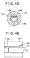
- the first rack bar 10B is set in split dies 107, 109 (FIG. 4D).
- the split dies 107, 109 have, on their upper internal peripheral surfaces, rack teeth-forming portions 107a, 109a, respectively.
- a punch 111 pressing member
- a punch 111 is inserted into the first rack bar 10B to press a portion (upper portion) of the first rack bar 10B out toward the rack teeth-forming portions 107a, 109a of the split dies 107, 109, thereby sequentially forming rack teeth (cold forming) (see FIG. 4E).
- Configurations of the rack teeth-forming portions 107a, 109a are set such that the rack tooth height L1 of the rack bar 10 becomes at most 1.5 times the bottom wall thickness L2, and so that the pressure angle ⁇ 1 becomes equal to 14.5 degrees.
- each of the rack teeth 12a is at most 1.5 times the bottom wall thickness L2 in the rack bar 10 of this embodiment formed as described above, the amount of metal displacement occurring when a portion of the tubular member 10A is pressed out toward the split dies 107, 109 to form each of the rack teeth 12a by inserting the punch 111 into the tubular member 10A can be reduced. Therefore, the forming rate of each of the rack teeth 12a can be reduced, and the forming quality of each of the rack teeth 12a can be improved.
- the rack bar 10 of this embodiment allows an increase in the distance r1 from the center axis to the bottom of the rack teeth 12a, so that the bending strength of the rack bar 10 can be increased and the volume of the rack teeth 12a can be reduced. Still further, the ,material of tubular member 10A is allowed to have a reduced wall thickness, so that a weight reduction is achieved.
- the rack teeth 12a of the rack bar 10 of the embodiment are angled at a helical angle greater than zero and less than or equal to 20 degrees (0 degree ⁇ helical angle ⁇ 20 degrees). Therefore, when the punch 111 is inserted into the tubular member 10A during the production process of the rack bar 10, each rack tooth 12a is formed in such a manner that material of the tubular member 10A is pressed out gradually from one end portion to the opposite end portion of the tooth in the direction of the tooth width. Therefore, the material flow is facilitated, so that formability improves, thereby contributing to an improvement in the quality of the rack teeth 12a.
Landscapes
- Engineering & Computer Science (AREA)
- Mechanical Engineering (AREA)
- Chemical & Material Sciences (AREA)
- Combustion & Propulsion (AREA)
- Transportation (AREA)
- Forging (AREA)
- Gears, Cams (AREA)
Abstract
Description
Claims (5)
- A rack bar (10) having a body (11) with a hollow cross section; and rack teeth (12a) formed in a portion of the body so as to mesh with a pinion, wherein a height of the rack teeth (L1) is at most 1.5 times a teeth bottom wall thickness (L2).
- The rack bar according to claim 1, wherein the rack teeth (12a) have a helix angle greater than zero and less than about 20°.
- A method for producing a rack bar (10), the method characterized by comprising:placing a die having a rack teeth-forming portion (107a, 109a) on at least a portion of an outer peripheral surface of a tubular member (10A);inserting a pressing member (111) into the tubular member (10A); andforming rack teeth (12a) between the rack teeth-forming portion (107a, 109a) and the pressing member (111) by pressing a portion of the tubular member toward rack teeth-forming portion (107a, 109a),
wherein a height of the rack teeth (L1) is at most 1.5 times a teeth bottom wall thickness(L2). - A rack bar (10) produced in accordance with the method of claim 3.
- The method according to claim 3, wherein the rack teeth (12a) formed have a helix angle greater than zero and less than about 20°.
A rack bar whose rack teeth are formed by disposing a die having a rack teeth-forming portion on an outer peripheral surface of a tubular member, and by inserting a pressing member into the tubular member. The tooth height of the rack teeth is at most 1.5 times the teeth bottom wall thickness and the helical angle is less than or equal to 20°.
Applications Claiming Priority (2)
| Application Number | Priority Date | Filing Date | Title |
|---|---|---|---|
| JP29292799A JP2001114114A (en) | 1999-10-14 | 1999-10-14 | Rack bar |
| JP29292799 | 1999-10-14 |
Publications (2)
| Publication Number | Publication Date |
|---|---|
| EP1092610A2 true EP1092610A2 (en) | 2001-04-18 |
| EP1092610A3 EP1092610A3 (en) | 2002-12-11 |
Family
ID=17788219
Family Applications (1)
| Application Number | Title | Priority Date | Filing Date |
|---|---|---|---|
| EP00122187A Withdrawn EP1092610A3 (en) | 1999-10-14 | 2000-10-12 | Rack bar and production method for the same |
Country Status (2)
| Country | Link |
|---|---|
| EP (1) | EP1092610A3 (en) |
| JP (1) | JP2001114114A (en) |
Cited By (4)
| Publication number | Priority date | Publication date | Assignee | Title |
|---|---|---|---|---|
| WO2006037167A1 (en) * | 2004-10-07 | 2006-04-13 | Bishop Innovation Limited | Steering rack |
| AU2005291841B2 (en) * | 2004-10-07 | 2010-04-01 | Bishop Innovation Limited | Steering rack |
| US8176763B2 (en) | 2006-12-22 | 2012-05-15 | Thyssenkrupp Presta Aktiengesellschaft | Steering rack |
| US8770054B2 (en) | 2009-12-14 | 2014-07-08 | Jtekt Corporation | Manufacturing method for hollow rack shaft, and hollow rack shaft |
Families Citing this family (1)
| Publication number | Priority date | Publication date | Assignee | Title |
|---|---|---|---|---|
| CN105202154A (en) * | 2014-06-19 | 2015-12-30 | 王仁方 | Anti-abrasion rack |
Citations (1)
| Publication number | Priority date | Publication date | Assignee | Title |
|---|---|---|---|---|
| JPH0986420A (en) | 1995-09-26 | 1997-03-31 | T R W S S J Kk | Variable pitch rack bar |
Family Cites Families (6)
| Publication number | Priority date | Publication date | Assignee | Title |
|---|---|---|---|---|
| GB2124935B (en) * | 1982-07-21 | 1985-08-14 | Cam Gears Ltd | A piston and cylinder assembly a power assisted steering gear which includes such an assembly and a method of forming a piston for such an assembly |
| GB2132513B (en) * | 1982-12-31 | 1985-12-11 | Cam Gears Ltd | A method of forming a rack member |
| JP2928427B2 (en) * | 1992-05-26 | 1999-08-03 | 株式会社チューブフォーミング | Apparatus and method for molding tubular rack bar |
| JPH09141354A (en) * | 1995-11-20 | 1997-06-03 | Aisin Seiki Co Ltd | Method for manufacturing high toothed spline of hollow shaft and hollow shaft provided with high toothed spline |
| EP0897767A1 (en) * | 1997-08-19 | 1999-02-24 | Trw Inc. | Vehicle steering rack and method of manufacturing the rack |
| JP3633253B2 (en) * | 1997-12-19 | 2005-03-30 | 日本精工株式会社 | Hollow rack shaft and manufacturing method thereof |
-
1999
- 1999-10-14 JP JP29292799A patent/JP2001114114A/en active Pending
-
2000
- 2000-10-12 EP EP00122187A patent/EP1092610A3/en not_active Withdrawn
Patent Citations (1)
| Publication number | Priority date | Publication date | Assignee | Title |
|---|---|---|---|---|
| JPH0986420A (en) | 1995-09-26 | 1997-03-31 | T R W S S J Kk | Variable pitch rack bar |
Cited By (4)
| Publication number | Priority date | Publication date | Assignee | Title |
|---|---|---|---|---|
| WO2006037167A1 (en) * | 2004-10-07 | 2006-04-13 | Bishop Innovation Limited | Steering rack |
| AU2005291841B2 (en) * | 2004-10-07 | 2010-04-01 | Bishop Innovation Limited | Steering rack |
| US8176763B2 (en) | 2006-12-22 | 2012-05-15 | Thyssenkrupp Presta Aktiengesellschaft | Steering rack |
| US8770054B2 (en) | 2009-12-14 | 2014-07-08 | Jtekt Corporation | Manufacturing method for hollow rack shaft, and hollow rack shaft |
Also Published As
| Publication number | Publication date |
|---|---|
| EP1092610A3 (en) | 2002-12-11 |
| JP2001114114A (en) | 2001-04-24 |
Similar Documents
| Publication | Publication Date | Title |
|---|---|---|
| DE102007051159A1 (en) | Internal-pressure-formed tubular elements and a method for hydroforming tubular elements for vehicles | |
| WO2009071437A1 (en) | Production method of highly dimensionally accurate half shells | |
| JP5136998B2 (en) | Hydraulic bulge method and hydraulic bulge product | |
| CN1075406C (en) | Method for producing rack | |
| US6442992B2 (en) | Hollow rack shaft and method of manufacturing the same | |
| DE102019200121A1 (en) | Crimp for connecting wires | |
| US20020090314A1 (en) | Process to manufacture a sintered part with a subsequent shaping of the green compact | |
| EP1092610A2 (en) | Rack bar and production method for the same | |
| US6289710B1 (en) | Method of manufacturing a hollow rack bar | |
| EP3081896B1 (en) | Metal-fixing-material-passage and method of manufacturing a header with a metal-fixing-material-passage | |
| EP2465717B1 (en) | Method for producing an inner door sheet with a bearing section and a door module holder | |
| CN1101706A (en) | Screw washer and method and mold for producing same | |
| JP3393448B2 (en) | Ring gear forming method for sheet metal plate | |
| JP2000202721A (en) | Method of manufacturing fork for universal joint | |
| JP3572826B2 (en) | Manufacturing method of bracket with bracket | |
| JP2885266B2 (en) | Forming method for sheet metal tooth profile parts | |
| KR100273662B1 (en) | Gear | |
| EP4199273A1 (en) | Method for producing a flat conductor | |
| JPH033726A (en) | Method of manufacturing helical gear cold stamping die | |
| JP3382796B2 (en) | Ring gear manufacturing method | |
| CN1178143A (en) | Load-bearing shaped part and method for manufacturing shaped parts | |
| US7665340B2 (en) | Method for manufacturing one piece turnbuckle | |
| JP3509019B2 (en) | Method for manufacturing bottomed internal gear, bottomed internal gear, and forging die for bottomed internal gear | |
| JP3744562B2 (en) | Press-formed parts and their processing methods | |
| CN1034884A (en) | Method for manufacturing outer ring body of bicycle flywheel |
Legal Events
| Date | Code | Title | Description |
|---|---|---|---|
| PUAI | Public reference made under article 153(3) epc to a published international application that has entered the european phase |
Free format text: ORIGINAL CODE: 0009012 |
|
| 17P | Request for examination filed |
Effective date: 20001012 |
|
| AK | Designated contracting states |
Kind code of ref document: A2 Designated state(s): AT BE CH CY DE DK ES FI FR GB GR IE IT LI LU MC NL PT SE |
|
| AX | Request for extension of the european patent |
Free format text: AL;LT;LV;MK;RO;SI |
|
| PUAL | Search report despatched |
Free format text: ORIGINAL CODE: 0009013 |
|
| AK | Designated contracting states |
Kind code of ref document: A3 Designated state(s): AT BE CH CY DE DK ES FI FR GB GR IE IT LI LU MC NL PT SE |
|
| AX | Request for extension of the european patent |
Free format text: AL;LT;LV;MK;RO;SI |
|
| AKX | Designation fees paid |
Designated state(s): DE FR GB |
|
| 17Q | First examination report despatched |
Effective date: 20040227 |
|
| STAA | Information on the status of an ep patent application or granted ep patent |
Free format text: STATUS: THE APPLICATION IS DEEMED TO BE WITHDRAWN |
|
| 18D | Application deemed to be withdrawn |
Effective date: 20040709 |