EP1092549B1 - Printing device and printing method - Google Patents
Printing device and printing method Download PDFInfo
- Publication number
- EP1092549B1 EP1092549B1 EP01100786A EP01100786A EP1092549B1 EP 1092549 B1 EP1092549 B1 EP 1092549B1 EP 01100786 A EP01100786 A EP 01100786A EP 01100786 A EP01100786 A EP 01100786A EP 1092549 B1 EP1092549 B1 EP 1092549B1
- Authority
- EP
- European Patent Office
- Prior art keywords
- paper
- type
- printing
- ink
- roll
- Prior art date
- Legal status (The legal status is an assumption and is not a legal conclusion. Google has not performed a legal analysis and makes no representation as to the accuracy of the status listed.)
- Expired - Lifetime
Links
- 238000007639 printing Methods 0.000 title claims description 127
- 238000000034 method Methods 0.000 title claims description 14
- 239000000976 ink Substances 0.000 description 146
- 238000001514 detection method Methods 0.000 description 28
- 238000012545 processing Methods 0.000 description 24
- 239000000975 dye Substances 0.000 description 18
- 239000000049 pigment Substances 0.000 description 18
- 239000003086 colorant Substances 0.000 description 16
- 239000004744 fabric Substances 0.000 description 12
- 239000000463 material Substances 0.000 description 8
- 230000005611 electricity Effects 0.000 description 4
- 230000002093 peripheral effect Effects 0.000 description 4
- 230000002441 reversible effect Effects 0.000 description 4
- 238000012360 testing method Methods 0.000 description 4
- 238000012546 transfer Methods 0.000 description 3
- 238000010276 construction Methods 0.000 description 2
- 238000010586 diagram Methods 0.000 description 2
- 230000000977 initiatory effect Effects 0.000 description 2
- 239000007788 liquid Substances 0.000 description 2
- XLYOFNOQVPJJNP-UHFFFAOYSA-N water Substances O XLYOFNOQVPJJNP-UHFFFAOYSA-N 0.000 description 2
- 238000010521 absorption reaction Methods 0.000 description 1
- 230000006978 adaptation Effects 0.000 description 1
- 238000013459 approach Methods 0.000 description 1
- 230000005540 biological transmission Effects 0.000 description 1
- 239000003795 chemical substances by application Substances 0.000 description 1
- 238000004040 coloring Methods 0.000 description 1
- 238000009792 diffusion process Methods 0.000 description 1
- 238000001704 evaporation Methods 0.000 description 1
- 239000012530 fluid Substances 0.000 description 1
- 238000010438 heat treatment Methods 0.000 description 1
- 238000007641 inkjet printing Methods 0.000 description 1
- 238000003825 pressing Methods 0.000 description 1
- 238000011160 research Methods 0.000 description 1
- 239000000126 substance Substances 0.000 description 1
- 230000003746 surface roughness Effects 0.000 description 1
- 238000011144 upstream manufacturing Methods 0.000 description 1
- 238000013022 venting Methods 0.000 description 1
- 239000002699 waste material Substances 0.000 description 1
Images




Classifications
-
- B—PERFORMING OPERATIONS; TRANSPORTING
- B41—PRINTING; LINING MACHINES; TYPEWRITERS; STAMPS
- B41J—TYPEWRITERS; SELECTIVE PRINTING MECHANISMS, i.e. MECHANISMS PRINTING OTHERWISE THAN FROM A FORME; CORRECTION OF TYPOGRAPHICAL ERRORS
- B41J15/00—Devices or arrangements of selective printing mechanisms, e.g. ink-jet printers or thermal printers, specially adapted for supporting or handling copy material in continuous form, e.g. webs
- B41J15/04—Supporting, feeding, or guiding devices; Mountings for web rolls or spindles
-
- B—PERFORMING OPERATIONS; TRANSPORTING
- B41—PRINTING; LINING MACHINES; TYPEWRITERS; STAMPS
- B41J—TYPEWRITERS; SELECTIVE PRINTING MECHANISMS, i.e. MECHANISMS PRINTING OTHERWISE THAN FROM A FORME; CORRECTION OF TYPOGRAPHICAL ERRORS
- B41J11/00—Devices or arrangements of selective printing mechanisms, e.g. ink-jet printers or thermal printers, for supporting or handling copy material in sheet or web form
- B41J11/009—Detecting type of paper, e.g. by automatic reading of a code that is printed on a paper package or on a paper roll or by sensing the grade of translucency of the paper
-
- B—PERFORMING OPERATIONS; TRANSPORTING
- B41—PRINTING; LINING MACHINES; TYPEWRITERS; STAMPS
- B41J—TYPEWRITERS; SELECTIVE PRINTING MECHANISMS, i.e. MECHANISMS PRINTING OTHERWISE THAN FROM A FORME; CORRECTION OF TYPOGRAPHICAL ERRORS
- B41J2/00—Typewriters or selective printing mechanisms characterised by the printing or marking process for which they are designed
- B41J2/005—Typewriters or selective printing mechanisms characterised by the printing or marking process for which they are designed characterised by bringing liquid or particles selectively into contact with a printing material
- B41J2/01—Ink jet
- B41J2/17—Ink jet characterised by ink handling
- B41J2/175—Ink supply systems ; Circuit parts therefor
- B41J2/17503—Ink cartridges
- B41J2/17543—Cartridge presence detection or type identification
-
- B—PERFORMING OPERATIONS; TRANSPORTING
- B41—PRINTING; LINING MACHINES; TYPEWRITERS; STAMPS
- B41J—TYPEWRITERS; SELECTIVE PRINTING MECHANISMS, i.e. MECHANISMS PRINTING OTHERWISE THAN FROM A FORME; CORRECTION OF TYPOGRAPHICAL ERRORS
- B41J2/00—Typewriters or selective printing mechanisms characterised by the printing or marking process for which they are designed
- B41J2/005—Typewriters or selective printing mechanisms characterised by the printing or marking process for which they are designed characterised by bringing liquid or particles selectively into contact with a printing material
- B41J2/01—Ink jet
- B41J2/17—Ink jet characterised by ink handling
- B41J2/195—Ink jet characterised by ink handling for monitoring ink quality
-
- B—PERFORMING OPERATIONS; TRANSPORTING
- B41—PRINTING; LINING MACHINES; TYPEWRITERS; STAMPS
- B41J—TYPEWRITERS; SELECTIVE PRINTING MECHANISMS, i.e. MECHANISMS PRINTING OTHERWISE THAN FROM A FORME; CORRECTION OF TYPOGRAPHICAL ERRORS
- B41J29/00—Details of, or accessories for, typewriters or selective printing mechanisms not otherwise provided for
- B41J29/38—Drives, motors, controls or automatic cut-off devices for the entire printing mechanism
- B41J29/393—Devices for controlling or analysing the entire machine ; Controlling or analysing mechanical parameters involving printing of test patterns
Definitions
- This invention relates to a printing device like a printer and printing method. More, specifically, this invention relates to a printing device for ejecting ink onto paper for printing, said device being able to carry out adequate printing according to type of the paper used, a print method used in said device, and an intermediate holding mechanism having holders to be used for charging paper roll of paper used onto said printing device.
- JP 63237970 discloses a printing method wherein the paper type is discriminated and printing parameters are set in accordance with first and second tracks of a holder on which paper may be rolled. The said tracks are such that the paper type may be detected in a stationary or rotating condition.
- said printing device comprises a plurality of ink flow paths provided in ink jet head and having each nozzle at its front end, ejecting elements for ejecting outwards ink contained in said respective ink flow paths, and electrical controller for electrically controlling said ejection elements.
- electrostrictive vibrator When using electrostrictive vibrator as said ejecting element, at least a part of walls of said ink flow paths is formed by flexible materials, and said electrostrictive vibrator is mounted on said walls. Said vibrator is electrically controlled by a controller at a predetermined timing, thereby to decrease the cross section of said ink paths to eject outward inks contained therein, thus printing on paper.
- thermal head When using thermal head as said ejecting element, a thermal head is provided on walls of said ink flow paths. Particular heating elements of said thermal head are electrically activated at a predetermined printing timing controlled by electrically controlling means, thereby to cause thermal expansion of ink contained in ink flow paths and to eject ink therein onto paper for printing thereof.
- a pair of carriage shafts 2, 2 are provided in a direction parallel to the axis of said platen 1, and a carriage 3 is provided on said carriage shafts 2 in a reciprocating manner.
- Said carriage 3 has an ink jet unit 4 for full color printing mounted thereon.
- said ink jet unit 4 has thereon 4 ink jet heads 5 corresponding respectively to four colors for full color printing and located each against said platen 1.
- Each ink jet head 5 has corresponding nozzle 6, these nozzles 6 being arranged in parallel manner to each other and opposing to said platen 1 as shown in Fig.2.
- Said ink jet heads 5 are fixed on a head mounting member 7 which is in turn supported by said carriage 3.
- a plurality of inlets 9 containing each auxiliary tanks 8 as buffer tanks for communicating with said respective nozzles 6 provided in said ink jet heads 5 are mounted on said carriage 3 behind said respective ink jet heads 5. Said respective inlets 9 are communicating with respective ink cartridges 10 of corresponding colors mounted detachably on said carriage 3.
- a pump unit 11 which is used for covering said nozzles 6 when not used to prevent ink therein from evaporating and for removing air bubbles or foreign substances stacked in said nozzles 6.
- Said pump unit 11 has a casing 13 having an opening 12 on the side of said carriage 3, said opening 12 having herein a cap body 14 which is reciprocally movable in the direction of said ink jet unit 4.
- Said cap body 14 has a plurality of openings 15 formed in a vertical oblong form so as to cover corresponding ink jet heads 5.
- Said each opening 15 has therein a gum liner 16, said liner 16 projecting outside from inside of circumference of said opening 15 to be pressed onto the circumference of corresponding ink jet head 5 in a airtight manner.
- Said ink jet heads 5 comprises a plurality of ink flow paths 17 arranged in parallel and communicating with respective nozzles 6, each of said ink flow paths 17 having thereon corresponding piezo electric elements 18 as electrostrictive vibrators for ejecting ink from the front end of respective nozzles 6.
- said cap body 14 of pump unit 11 has an approximately semispherical protrusion 19 provided on the front upper side thereof, and an air pressure channel 20 is formed from the summit of said protrusion 19 up to the rear side surface of said cap body 14, a pressurizing means such as pump (not shown) being connected to said air pressure channel 20.
- Said respective openings 15 of said cap body 14 is communicated with venting valves (not-shown) through communicating channels 22.
- said respective openings 15 are provided with fluid exhausting pipes 23. These exhausting pipes 23 are connected to corresponding absorbing means such as pumps (not-shown) which absorb remaining portion of ink from respective opening 15 to be stored in a waste ink tank (not-shown).
- an air pressure channel 25 is provided on the upper portion of side surface of said head mounting member 7 opposing to said pump unit 11, said air pressure channel 25 being used for receiving said protrusion 19 in a nozzle touch manner therein to communicating with said pressure air channel 20 when said pump unit 11 covers said ink jet unit 4.
- Said air pressure channel 25 is further branched into four branch channels 26 corresponding in number to said ink cartridges 10. The end portion of said respective branch channels 26 is connected to air pipes 27 communicating respectively with the upper portion of respective ink cartridges 10.
- said cap body 14 of said pump unit 11 is first put aside when printing, and said carriage 3 mounting said ink jet unit 4 is run along said platen 1, while at the same time said piezo electric elements 18 of said nozzles 6 for printing use are driven by feeding electricity thereto on the basis of predetermined printing signals, thereby feeding ink from said ink cartridges 10 through said inlets 9 into said ink flow paths 17 and ejecting through said nozzles 6 onto printing paper on said platen.
- the coloring materials used in ink for printing devices are divided into two types, that is dyestuff and pigment.
- the dyestuff type is superior to said pigment type in the freshness of colors while rather weak when exposed to water and light.
- said pigment type is inferior to said dyestuff type in freshness of colors while strong against water and light.
- ink and paper have different physical characteristic as described above, it must be advantageous to use different types of ink and paper in a single printing apparatus thereby to settle different printing conditions for obtaining a wide variety of printing.
- Table 1 shows the results of a printing test on various types of paper using a dyestuff type ink in the conventional printing device.
- Type of Ink Type of Paper Printing Mode Result Remark Dyestuff Fine type Standard Good Dyestuff Back Print Standard Good Dyestuff Cloth Standard Good
- any type of paper such as fine type, back print type and cloth could be printed with good result in a standard printing mode by using a dyestuff type of ink.
- Table 2 shows a printing test on various types of paper using pigment type of ink in a heretofore known printing device.
- Type of Ink Type of Paper Printing Mode Result Remarks Pigment Fine type Standard Bad() () Pigment Back Print Standard Bad() () Pigment Cloth Standard Bad() ()
- this invention has as its object to deliver a printing device which can carry out always a high quality of printing while taking into consideration the types of ink and paper used, and having a means for automatically detecting the type of paper, and a printing method using said printing device as well as an intermediate holder for charging a roll of paper to be used into the printing device.
- printing method as claimed in Claim 2 which is characterised in that the color element comprises at least one of color and color concentration of the holder (81).
- printing method as claimed in Claim 4 which is characterised in that the color element comprises at least one of color and color concentration of the holder (81).
- An embodiment of printing device according to the present invention as shown in Fig.3 and Fig.4, has a housing 30, in which a cylindrical platen 1 is rotatably mounted with its axis extending in horizontal direction.
- a driven pulley (not-shown) is supported by one end of said platen 1, a belt 32 driven by a first reversible motor 31 being wound on said driven pulley. Accordingly, said platen 1 can be driven by driving force of said first motor 31 in the normal transporting direction or in the reverse direction.
- a paper roll 33 having an axis parallel to said platen 1 is mounted on the rear side of said platen 1 in said housing 30.
- roll paper 33a to be used is released out of paper roll 33 to be wound on the upper side of said platen 1.
- An ink jet unit 4 reciprocating along said platen 1 in a direction parallel to the axis thereof is provided in the space opposing to said platen 1 in said housing 30.
- a carriage 3 of said ink jet unit 4 has thereon a plurality of ink jet heads (not-shown) which are directed against said platen 1.
- a driving belt 34 is connected to said ink jet unit 4, and said driving belt 34 is wound about a driving pulley 36 which is driven by a second motor 35 of reversible type. Accordingly, when driving said second motor 35, said ink jet unit 4 is reciprocated along said platen 1 under the guidance of a carriage 2 located in parallel to said platen 1.
- a pump unit 11 for covering the nozzles of restrictive ink jet heads of said ink jet unit 4 for the purpose of recovering operation thereof is located on one side of the other end portion of said platen 1, and an exhaust liquid tank 37 is provided adjacent to said pump unit 11
- Photointerrupters 38 of transmission type are located with a distance therebetween in the front and back direction of said carriage 3 on the underside of said carriage 3 of said ink jet unit 4, and a linear encoder 39 comprising a thin plate having therein a number of small holes corresponding to printing resolution is located along the whole range of shifting ink jet unit 4.
- Cutter 40 consisting of long sized fixed blade 41 and movable blade 42 for cutting printed roll paper 33a is located below said platen 1 and ink jet unit 4.
- a first paper detector 43 for detecting roll paper 33a on said platen 1 is located on the upstream side of said ink jet unit 4 in the normal conveying direction of said roll paper 33a so as to oppose to said platen 1, while second paper detector 44 is located between said ink jet unit 4 and said cutter 40.
- Said both paper detectors 43, 44 and said both motors 31, 35 are respectively connected to a controller 45 of printing device, so that when signals about roll paper 33a from said paper detectors 43, 44 are input into said controller 45, this controller 45 controls said respective motor 31, 35 correspondingly to the input signals.
- the upper opening (not-shown) is covered by a closing cover 30A.
- Fig.5 shows a control block diagram of printing device including said controller 45.
- said controller 45 as electricity feeding control portion of the whole printing device consists of a mother board 46 having a control panel; a CPU board 47, a mechanical control board 48 and a head control board 49 connected to each other via said mother board 46; and an ink detection board 50 and a head drive board 51 connected to said head control board 49.
- Said CPU board 47 has built-in CPU, ROM, RAM and the like, among which ROM has programs for operation and graphic processing written therein.
- Said head control board 49 is connected to and controls a detection unit of paper type 52 for detecting the type of paper to be used correspondingly to signals from said CPU; said pump unit 11; a CR unit 53 for driving said second motor 35 shifting said ink jet unit 4; a LF unit 54 for driving said first motor 31 conveying said roll paper 33a.
- Said mechanical control board 48 includes drivers (not shown) for driving said detection unit of paper type 52, pump unit 11, CR unit 53 and LF unit 54. Further, said mechanical control board 48 can transfer signals from said exhaust liquid tank 37 and said detection unit of paper type 52 to said CPU of said CPU board 47.
- Said head control board 49 transfers a detection signal of residual ink quantity detected by said ink detection board 50 located on said ink jet unit 4 to said CPU of said CPU board 47, and, in said head drive board 51, said head control board 49 also transfers logical signals based on information from said CPU for driving said ink jet unit 4. Based on said logical signals, said head drive board 51 generates driving signals for driving respective ink jet head 5 and respective ink cartridge 10. For exchanging ink types, said ink cartridge 10 must be exchanged.
- said linear encoder 39 is connected in parallel to said second motor 35, said linear encoder 39 outputting to said CPU of said CPU board 47 signals correspondingly to rotational speed of said second motor 35 for equalizing the shifting speed of said ink jet unit 4.
- said mother board 46 is provided with interface unit (I/F) 57, 58 for connecting this printing device to personal computer and the like.
- I/F interface unit
- said paper roll 33 is supported on a pair of roll holders 62a, 62b of a roll holding mechanism 62 located on left and right portions of base 61 of printing device with a suitable distance between them.
- a holder pair i.e. roll holder 62b on the right side is detachably mounted in any positions provided on a holder supporting plate 63 so as to be shifted according to the width of said roll paper 33a.
- said paper roll 33 comprises said roll paper 33a wound on a paper tube (not shown), said paper tube having paper tube holders 33b, 33b mounted on its both ends, and these paper tube holders being held respectively by said roll holder 62a, 62b.
- Said each paper tube holder 33b, 33b has round flange portion 33c having a diameter larger than that of roll paper 33a.
- the iameter of said flange portions 33c has different size according to the type of roll paper 33a wound on said paper tube, i.e. common paper, coat paper, film for OHP, back print film, burnished film and the like. Accordingly, one can identify the paper type according to the diameter of flanges 33c used.
- said detection unit of paper type 52 for outputting detection signals for detecting type of said roll paper 33a has a base plate 64 located adjacent to one of said roll holders 62a. Said base plate 64 supports above it a pair of parallel guide rods 65, 65 which are parallel to each other and extend in horizontal direction so as to vertically cross the axis of said paper roll 33.
- a sliding table 66 is mounted on said guide rods 65, 65 so as to shift along the extending direction of said guide rods 65.
- a bracket 67 extends upwardly on the one end of said sliding table 66, and said bracket 67 supports thereon a flange abutting block member 68 having its one side surface 68a used as A flange abutting surface.
- a coil spring 69 is provided between said base plate 64 and said sliding table 66 so as to urges said sliding table 66 in the direction A shown in Fig. 8 for pressing said flange abutting member 68 onto said flange 33c of said paper roll 33.
- a wire 70 as a manipulating member is connected to said bracket 67.
- a hollow tube 71 is fixed on a edge portion of said base plate 64 so as to extend from the fixing point of said wire 70 on said bracket 67 in a reverse direction B to the urging direction A of said coil spring 69.
- Said wire 70 passes through said tube 71 and extends outside of said base plate 64, the other end of said wire 70 being fixed onto said cover 30A (Fig.4). Consequently, when opening said cover 30A, said sliding table 66 is shifted by said wire 70 in the direction B against the urging force of said coil spring 69.
- said flange abutting member 68 as an example of roll holder abutting member is retracted into a retracted position. Further, when said cover 30A is closed, said wire 70 is relaxed and said sliding table 66 is pulled in the direction A due to the urging force of said coil spring 69.
- each photosensor 72A, 72B, 72C and an output connector 73 for outputting signals from respective sensors 72 to said controller 45 are located on said base plate 64, Said respective sensors 72 have respectively a U-form, and three state setting sheets 75 having each plate form to be inserted into the hollow portions of corresponding sensors 72 are supported on the rear side surface of said sliding table 66 so as to engage into respective sensors 72.
- Each state setting sheet 75 is a shielding plate for shielding light from light emitting portion of each sensor so as not to reach light receiving portion thereof, while said state setting sheet 75 has slits (not shown) allowing light from light emitting portion thereof to reach light receiving portion thereof.
- Each sensor 72 has a construction such that it outputs signal ON when light from light emitting portion reaches light receiving portion, while it outputs signal OFF when light from light emitting portion does not reach light receiving portion.
- the position of sliding table 66 with respect to said base plate 64 is changed correspondingly to diameter of said flange 33c at the end of paper roll 33.
- each sensor 72A, 72B and 72C outputs ON signal or OFF signal to said CPU board 47 (Fig.5) according to the position of said slits of corresponding state setting sheet 75.
- Said CPU of said CPU board 47 can thus detect the type of paper (roll paper 33a) according to the flange diameter obtained by combination of ON or OFF signals issued from respective three sensors 72 as shown in the following Table 3.
- the types of paper thus detected are output to said CPU board 47 and are displayed on a displaying panel (not shown) of ink jet printing device.
- Sensors A, B and C shown in this Table designated respectively said sensors 72A, 72B and 72C.
- Paper Type Flange Diameter (mm) Sensor A Sensor B Sensor C No paper 0 ON ON ON 1 48 - 52 OFF ON OFF 2 58 - 62 OFF OFF ON 3 70 - 74 ON OFF ON 4 80 - 84 OFF ON ON 5 88 - 92 ON ON OFF 6 98 -102 ON OFF OFF OFF
- Said CPU board 47 can carry out image processing and driving of ink jet heads 5 shown in Table 4 correspondingly to detected type of paper.
- Paper type 1 - 3 can be adequately processed by the standard setting of printing device, but not Paper types 4 - 6.
- cover 30A is opened for mounting a paper roll 33 including a desired type of roll paper 33a onto roll holding mechanism 62.
- Wire 70 connected to this cover 30A is thus pulled in the direction B against the urging force of coil spring 69, so that sliding table 66 connected to this wire 70 is also pulled in the same direction B and flange abutting member 68 is retracted into a retraction place so as not to impede inserting operation of paper roll 33.
- holders 33b having each flange 33c of outer diameter adapted to that of roll paper 33a mount paper roll 33 on both roll holders 62a, 62b of roll holding mechanism 62.
- CPU of CPU board 47 Upon switching printing device electric source into ON, CPU of CPU board 47 initializes respective parts 48, 49, 50, 51 and respective units 4, 11, 52, 53, 54 and then recognizes type of paper use, i.e. anything of fine type paper, back print type, cloth and the like.
- type of paper can be automatically detected upon mounting of said paper roll 33 onto roll holder 62a, 62b as described above, double printing and/or inferior image quality due to input error of paper type by operator can be prevented. Further, since paper used is automatically detected according to outer diameter of flanges 33c, more various types of paper can be handled by increasing the number of sensors. Further, since flange abutting member 68 is retracted when exchanging paper roll 33, flange abutting member 68 does not impede the exchange of paper roll 33.
- said CPU receives signals for recognizing ink type, i.e. dyestuff type or pigment type.
- said CPU looks up data table written in ROM of said CPU board 47, thereby to set driving conditions of ink jet head 5 such as driving voltage and frequency adapting to said detected ink type and to set also an image processing mode adapting to detected paper type.
- driving voltage adapting to ink type is 80V when using dyestuff type ink and 70V when using pigment type ink
- example of driving frequency adapting to ink type is 3.0 KHz for dyestuff type ink and 2.7 KHz for pigment type ink.
- said CPU sets an image processing mode adapting to said type of paper.
- This image processing mode comprises dedicated image processing A adapting to fine type paper, dedicated image processing B adapting to back print type paper and dedicated image processing C adapting to cloth type materials.
- said dedicated image processing A when fine type paper can absorb no more ink at overlapping of a number of ink colors, bringing about too much dot number per surface unit with a too much high ink concentration, said dot number aimed at paper from ink jet head 5 is reduced so as to improve absorption of ink into paper.
- said dedicated image processing B which is adaptable to back print type paper, in the case when black color on paper is too low, in place of using only black ink for forming black image, cian ink, magenta ink and yellow ink are overlapped on a black image formed by black ink, uniformly and with a reduced proportion of dot number of said black ink from ink jet head 5, thereby to increase concentration of black image.
- said dedicated image processing C which is adaptable to materials tending to absorb too much ink such as cloth, when ink concentration on printing materials as a whole is too much low, all ink colors are double printed on all dot points.
- CPU researches operation history of the printing device concerned for carrying out initiating process. of printing based upon said operation history.
- said CPU determines back feeding quantity of roll paper 33a correspondingly to the front end position of roll paper 33a detected by said second paper detector 44 and sets roll paper 33a at the printing beginning position.
- Printing information such as images and characters which is fed following said printing beginning command is processed into printing data adapting to ink type and paper type used, and these printing data are stored in RAM in said CPU board 47.
- said CPU of said CPU board 47 sends command to second motor 35 in said CR unit 53, and adjust said command based on signals from said linear encoder 39, thus servocontrolling for unifying shifting velocity of said ink jet unit 4 thereby to stabilize printing quality.
- said printing data stored in RAM of said CPU board 47 are input into ink jet unit 4 as driving signals to respective ink jet heads 5, synchronously with signals from said liner encoder 39, via said head control board 49 and head drive board 51 for ejecting ink from nozzles of these ink jet heads 5 and printing desired dots on roll paper 33a.
- the rear portion of said roll paper 33a is cut by said cutting section 40 to form a separate sheet and to exhaust this paper sheet thereby to obtain a printed sheet of paper.
- Table 5 shows the test results wherein three types of materials, i.e. fine type, back print type and cloth were printed using two types of ink, i.e. dyestuff type and pigment type in the printing device according to the invention.
- Type of Ink Type of Paper Driving Volt of Head Driving Frequency of Head Image Processing Mode Result Dyestuff Fine 80V 3.0KHz Standard Good Dyestuff Back Print 80V 3.0KHz Standard Good Dyestuff Cloth 80V 3.0KHz Standard Good Pigment Fine 70V 2.7KHz Processing A Good Pigment Back Print 70V 2.7KHz Processing B Good Pigment Cloth 70V 2.7KHz Processing C Good
- ink jet head 5 when printing was carried out using dyestuff type ink, with driving conditions of ink jet head 5 such as driving volt of 80V and driving frequency of 3.0KHz and standard image processing mode, ink ejected from nozzles of ink jet head 5 runs straight forward and reaches upon printing materials in a stable manner, so that any type of materials such a fine type, back print type and cloth could be printed with excellent printing quality.
- driving conditions of ink jet head 5 such as driving volt of 80V and driving frequency of 3.0KHz and standard image processing mode
- second embodiment of printing device which can discriminate automatically the types of paper used is shown diagrammatically. Only the portions which are different from those of the first embodiment, specifically which are related to detection of paper are described below.
- Paper roll 80 used in this embodiment comprises a tube core 80a and roll paper 80b wound on said core 88a.
- a holder 81 as intermediate holder is mounted on the one end of said core 80a.
- Said holder 81 comprises a cylindrical tube 81a fitted into said core 80a, a holder body 81b connected to said fitted tube 81a as a unit and having a larger outer diameter than that of said core 80a, and a flange 81c as a disc formed on the periphery of said holder body 81b at its inner end and having a larger diameter than the largest diameter of said paper roll 80b.
- the peripheral surface of said holder body 81b has a predetermined color, so that the combination of predetermined outer diameter and color of particular holder body 81b can specify the type of roll paper 80b held by the holder 81, i.e. common paper, coat paper, film for OHP, back print film, burnished paper and the like.
- outer diameter and color of holder body 81b are used as discriminating elements of type of roll paper 80b according to the invention.
- said discriminating colors can be different colors such as red or blue, or can have different concentration of the same color. Otherwise, in place of holder body 81, diameter and color of said flange 81c formed on said holder body 81b can be detected.
- additional holder 82 of usual shape which does not contribute to detection of paper type is attached on the other end of said core 80a. Further, said holder 81 has an auxiliary holder 83 fitted thereinto, so that said paper roll 80 is charged into roll holders 62a, 62b of roll holding mechanism 62.
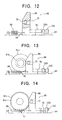
- Said paper type detection unit 52 which outputs signals for detection of type of said roll paper 80b has, as shown in Fig.12, a sliding unit 66 which is slidable on a base plate 64 in the direction to and from said holder 81 (Fig.10).
- a holder abutting member 68 projects from the upper side surface of said sliding table 66, the front side of said holder abutting member 68 being opposed against the peripheral surface of said holder body 81b.
- One end of said sliding table 66 supports a coil spring 69 which urges said holder abutting member 68 so as to approach said paper roll 80.
- a small hole 76 is formed on the front side surface 68a of said holder abutting member 68 so as to be opposed to said peripheral surface of said holder body 81b, said small hole 67 serving as means for reading the discriminating agent, i.e. outer diameter and color of said holder body 81b.
- a light sensor 77 is provided in said holder abutting element 68 so as to be opposed to said holder body 81b through said small hole 76.
- a shield plate 78 as a state setting member protrudes from said holder abutting member 68 in the horizontal direction on the side contrary to said urging direction of said sliding table 66.
- two sets of photosensors 72D, 72E are located with a distance between them in the shift direction of said shield plate 78 so that photodiode and phototransistor thereof are opposed to each other on both sides of shifting way of said shield plate 78.
- said shield plate 78 protruding from said sliding table 66 changes its stopping position correspondingly to that of said sliding table 66 changing also according to outer diameter of said holder body 81b, so that signals from said both photosensors 72D, 72E allow for detecting outer diameter of said holder 81b.
- a stopper 79 protrudes from the upper surface of said base plate 64 for the purpose of stopping said sliding table 66 in a state where said shield plate 78 is not opposed to said both photosensors 72D, 72E as a result of urging of said sliding table 66 by said coil spring 69 when said paper roll 80 is not charged in said printing device. Since other components comprising said paper type detection unit 52 are the same as those of the above described embodiment, these other components are not described herein in detail.
- detection of paper type is carried out based upon data detected both first paper type detection unit for detecting type of roll paper 80b based on the position of said flange abutting member 68, and second paper type detection unit for detecting the color element of said holder body 81b corresponding to type of said roll paper 80b.
- said first paper type detection unit consists of two sets of photosensors 72D, 72E for detecting the stopping position of said shield plate 78.
- said shield plate 78 take a position where it is not opposed any of sensors 72D, 72E.
- said sliding table 66 is pulled by the urging force of said coil spring 69.
- said table 66 takes a backward position in comparison to Fig.12, so that said shield plate 78 is not opposed to one photograph 72E, but shields only the other photosensor 72D which is nearer to said paper roll 80.
- said flange abutting member 68 is retracted farther, as a result of which said shield plate 78 comes to shield both photosensors 72D, 72E. Accordingly, any of ON signal and OFF signal is output from said sensors 72D, 72E correspondingly to outer diameter of holder body 81b holding paper roll 80 charged into said printing device.
- said light sensor 77 as second paper type detection unit is opposed to holder body 81b for detecting its color or concentration, as shown in Fig.13.
- Said CPU board 47 detects the type of paper (roll paper 80b) due to the combination of ON/OFF signal from said first paper type detector and signals showing color elements obtained from said second paper type detector.
- said light sensor 77 discriminates two types of color, for example black and white
- the combination of colors and outer diameters of said holder body 81b allows for detection of 2 X 2, i.e. four types of paper.
- This information is output from said output connector 73 to said CPU board 47, which detects types of paper based on signals of said three sensors output from said paper type detection unit 52 and issues instructions for predetermined image processing and head driving correspondingly to types of paper thus detected. It goes without saying that relationship between the combination of colors and diameters of holder 81 and the types of paper is preset in ROM of CPU and the like.
- control board 45 can issue an alarm requesting exchange of paper or print mode.
Landscapes
- Engineering & Computer Science (AREA)
- Quality & Reliability (AREA)
- Ink Jet (AREA)
- Particle Formation And Scattering Control In Inkjet Printers (AREA)
Description
- This invention relates to a printing device like a printer and printing method. More, specifically, this invention relates to a printing device for ejecting ink onto paper for printing, said device being able to carry out adequate printing according to type of the paper used, a print method used in said device, and an intermediate holding mechanism having holders to be used for charging paper roll of paper used onto said printing device.
- JP 63237970 discloses a printing method wherein the paper type is discriminated and printing parameters are set in accordance with first and second tracks of a holder on which paper may be rolled. The said tracks are such that the paper type may be detected in a stationary or rotating condition.
- In general, said printing device comprises a plurality of ink flow paths provided in ink jet head and having each nozzle at its front end, ejecting elements for ejecting outwards ink contained in said respective ink flow paths, and electrical controller for electrically controlling said ejection elements.
- When using electrostrictive vibrator as said ejecting element, at least a part of walls of said ink flow paths is formed by flexible materials, and said electrostrictive vibrator is mounted on said walls. Said vibrator is electrically controlled by a controller at a predetermined timing, thereby to decrease the cross section of said ink paths to eject outward inks contained therein, thus printing on paper.
- When using thermal head as said ejecting element, a thermal head is provided on walls of said ink flow paths. Particular heating elements of said thermal head are electrically activated at a predetermined printing timing controlled by electrically controlling means, thereby to cause thermal expansion of ink contained in ink flow paths and to eject ink therein onto paper for printing thereof.
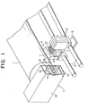
- Heretofore known type of said printing device having electrostrictive vibrator is described herein below with reference to Fig.1 and Fig.2.
- With reference to Fig.1, in front of a cylindrical platen 1, a pair of
carriage shafts carriage 3 is provided on saidcarriage shafts 2 in a reciprocating manner. Saidcarriage 3 has anink jet unit 4 for full color printing mounted thereon. - As shown in Fig.2, said
ink jet unit 4 has thereon 4ink jet heads 5 corresponding respectively to four colors for full color printing and located each against said platen 1. Eachink jet head 5 hascorresponding nozzle 6, thesenozzles 6 being arranged in parallel manner to each other and opposing to said platen 1 as shown in Fig.2. Saidink jet heads 5 are fixed on ahead mounting member 7 which is in turn supported by saidcarriage 3. - A plurality of
inlets 9 containing each auxiliary tanks 8 as buffer tanks for communicating with saidrespective nozzles 6 provided in saidink jet heads 5 are mounted on saidcarriage 3 behind said respectiveink jet heads 5. Saidrespective inlets 9 are communicating withrespective ink cartridges 10 of corresponding colors mounted detachably on saidcarriage 3. - On the outer side of one end of said
platen 10, there is provided apump unit 11 which is used for covering saidnozzles 6 when not used to prevent ink therein from evaporating and for removing air bubbles or foreign substances stacked in saidnozzles 6. Saidpump unit 11 has acasing 13 having anopening 12 on the side of saidcarriage 3, said opening 12 having herein acap body 14 which is reciprocally movable in the direction of saidink jet unit 4. Saidcap body 14 has a plurality ofopenings 15 formed in a vertical oblong form so as to cover correspondingink jet heads 5. Said each opening 15 has therein agum liner 16, saidliner 16 projecting outside from inside of circumference of said opening 15 to be pressed onto the circumference of correspondingink jet head 5 in a airtight manner. - Said
ink jet heads 5 comprises a plurality ofink flow paths 17 arranged in parallel and communicating withrespective nozzles 6, each of saidink flow paths 17 having thereon corresponding piezoelectric elements 18 as electrostrictive vibrators for ejecting ink from the front end ofrespective nozzles 6. - On the one hand, said
cap body 14 ofpump unit 11 has an approximatelysemispherical protrusion 19 provided on the front upper side thereof, and anair pressure channel 20 is formed from the summit of saidprotrusion 19 up to the rear side surface of saidcap body 14, a pressurizing means such as pump (not shown) being connected to saidair pressure channel 20. Saidrespective openings 15 of saidcap body 14 is communicated with venting valves (not-shown) through communicatingchannels 22. Further, saidrespective openings 15 are provided with fluidexhausting pipes 23. Theseexhausting pipes 23 are connected to corresponding absorbing means such as pumps (not-shown) which absorb remaining portion of ink from respective opening 15 to be stored in a waste ink tank (not-shown). - On the other hand, an
air pressure channel 25 is provided on the upper portion of side surface of saidhead mounting member 7 opposing to saidpump unit 11, saidair pressure channel 25 being used for receiving saidprotrusion 19 in a nozzle touch manner therein to communicating with saidpressure air channel 20 when saidpump unit 11 covers saidink jet unit 4. Saidair pressure channel 25 is further branched into fourbranch channels 26 corresponding in number to saidink cartridges 10. The end portion of saidrespective branch channels 26 is connected toair pipes 27 communicating respectively with the upper portion ofrespective ink cartridges 10. - In the construction as described above of heretofore known printing device, said
cap body 14 of saidpump unit 11 is first put aside when printing, and saidcarriage 3 mounting saidink jet unit 4 is run along said platen 1, while at the same time said piezoelectric elements 18 of saidnozzles 6 for printing use are driven by feeding electricity thereto on the basis of predetermined printing signals, thereby feeding ink from saidink cartridges 10 through saidinlets 9 into saidink flow paths 17 and ejecting through saidnozzles 6 onto printing paper on said platen. - In general, the coloring materials used in ink for printing devices are divided into two types, that is dyestuff and pigment. The dyestuff type is superior to said pigment type in the freshness of colors while rather weak when exposed to water and light. On the other hand, said pigment type is inferior to said dyestuff type in freshness of colors while strong against water and light.
- With respect to printing paper, there are two types of papers, one type being easier to absorb or receive ink and the other type being rather hard to receive ink. In the former type of paper, absorbed ink is more rapidly diffused so that the total amount of ink used is less than that of the latter type of paper which is more hard to absorb ink. However, the former type of paper which absorbs more easily ink has inferior to the latter type due to said ink diffusion phenomenon.
- Since ink and paper have different physical characteristic as described above, it must be advantageous to use different types of ink and paper in a single printing apparatus thereby to settle different printing conditions for obtaining a wide variety of printing.
- However, only one type of ink could be used in the heretofore known printing devices.
- This is because the upper limits of electricity feeding conditions such as voltage and frequency for driving ink jet head are different for different types of coloring agent used in an ink even when physical characteristics such as viscosity and surface tension of ink are held constant, so that, if driving pressure and frequency corresponding to the type of coloring agent are not used for driving ink jet head, a constant direction of ink ejection can not be obtained, resulting in a poor printing quality.
- Further, with respect to the type of paper used, only a particular type of paper can be used for a particular ink used due to variations of printing quality caused by the absorbing capacity of ink used.
- Table 1 shows the results of a printing test on various types of paper using a dyestuff type ink in the conventional printing device.
Type of Ink Type of Paper Printing Mode Result Remark Dyestuff Fine type Standard Good Dyestuff Back Print Standard Good Dyestuff Cloth Standard Good - As shown in Table 1, any type of paper such as fine type, back print type and cloth could be printed with good result in a standard printing mode by using a dyestuff type of ink.
- Table 2 shows a printing test on various types of paper using pigment type of ink in a heretofore known printing device.
Type of Ink Type of Paper Printing Mode Result Remarks Pigment Fine type Standard Bad() () Pigment Back Print Standard Bad() () Pigment Cloth Standard Bad() () - As shown in Table 2 , when printing was carried out using a pigment type ink at standard printing mode, good printing could not obtained on any type of paper. This is due to the fact that said
ink jet heads 6 were driven at the same electricity feeding conditions as those in the case using dyestuff type ink in spite of using herein pigment type ink in place of dyestuff type ink, with the results that the ejection direction of ink was not constant and ink could not ejected. - With respect to paper used in this test, ink was not absorbed into paper at places having higher ink concentration when using a fine type paper. When using back print type paper, black ink was so much absorbed in this type of paper, with the result that only black color had a low concentration. Lastly, when using cloth as printing paper, all of four color ines have been absorbed too much into paper, with the result of four colors having each lower concentration.
- In general, users of printing device have input the type of paper used into printing device by any means. One of these means has been setting of the type of paper on the operating panel of printing device by user. More recently, the information about type of paper to be used is often transferred into printing device from personal computer together with printing data. In the last case, user selects his desired type of paper from Paper Menu printed on a software called Printer Driver containing types of paper such as common paper, coat paper, film for a overhead projector (OHP), back print film, burnished paper and the like.
- On the other hand, while there are several cases where one can easily discriminate paper used by means of appearance thereof and touch feeling thereon, there are so many papers which have resembling appearance and feeling. Therefore, when users set erroneously types of paper, printing can not be carried out at printing conditions adapted to the type of paper used, resulting in undetected printing quality.
- While it is possible to discriminate types of paper used through its factors such as surface roughness, light transparency and rigidity, but it is not practical to mount detection mechanism for that purpose upon printing device, because one detection device is necessary for anything of said paper factors, thus increasing considerably the cost or printing device. When detecting type of paper using the factor of light transparency, only three states if paper, i.e. transparent, translucent and opaque, which limits adaptation to more and more various types of paper. As described above, direct detection of paper type has been difficult in technical and economical viewpoints.
- Accordingly, this invention has as its object to deliver a printing device which can carry out always a high quality of printing while taking into consideration the types of ink and paper used, and having a means for automatically detecting the type of paper, and a printing method using said printing device as well as an intermediate holder for charging a roll of paper to be used into the printing device.
- A printing method for printing on paper wound in the form of paper roll (80) described in Claim 1, which comprises the steps of storing printing conditions for a plurality of paper types, discriminating type of paper used and controlling the operation of said printing device to carry out printing on the basis of corresponding printing conditions, characterised in that the type of paper used is discriminated by a single discriminating element (81b), and in that an outer diameter or colour element (80) of at least one holder (81) mounted on the paper roll (80) is used as the discriminating element (81b).
- Further, printing method as claimed in
Claim 2, which is characterised in that the color element comprises at least one of color and color concentration of the holder (81). - A printing method for printing on paper wound in the form of paper roll (80) as described in
Claim 3, which comprises the steps of storing printing conditions for a plurality of paper types, discriminating type of paper used and controlling the operation of said printing device to carry out printing on the basis of corresponding printing conditions, the type of paper used is discriminated by combination of a plurality of discriminating elements (81b), characterised in that the plurality of discriminating elements comprise an outer diameter of at least one holder (81) mounted on the paper roll (80) and color elements of the holder (81). - Further, printing method as claimed in
Claim 4, which is characterised in that the color element comprises at least one of color and color concentration of the holder (81). -
- Fig.1 is a perspective view of essential portion of heretofore known printing device;
- Fig.2 is a cross-sectional view of Fig.1;
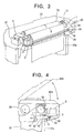
- Fig.3 is a perspective view showing a first embodiment of printing device according to the invention;
- Fig.4 is a partial side view of printing device shown in Fig. 3;
- Fig.5 is a block diagram of printing device shown in Fig.3 and Fig.4;
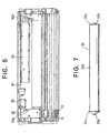
- Fig.6 is a plan view showing roll holding mechanism in the first embodiment;
- Fig.7 is a front view of paper roll used in the first embodiment;
- Fig.8 is an enlarged perspective view of paper type detection means (unit) used in Fig. 6;
- Fig.9 is a perspective view of essential portion of Fig.8;
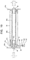
- Fig.10 is a cross-sectional view showing paper roll and paper type detection means used in second embodiment of the invention;
- Fig.11 is an exploded perspective view shown holding mechanism at one end of paper roll; and
- Fig.12, Fig.13 and Fig.14 are side views showing the steps of action of paper type detection means.
-
- An embodiment of printing device according to the present invention as shown in Fig.3 and Fig.4, has a
housing 30, in which a cylindrical platen 1 is rotatably mounted with its axis extending in horizontal direction. A driven pulley (not-shown) is supported by one end of said platen 1, a belt 32 driven by a firstreversible motor 31 being wound on said driven pulley. Accordingly, said platen 1 can be driven by driving force of saidfirst motor 31 in the normal transporting direction or in the reverse direction. - A
paper roll 33 having an axis parallel to said platen 1 is mounted on the rear side of said platen 1 in saidhousing 30. When saidpaper roll 33 is rotated in counter-clock direction in Fig.4, rollpaper 33a to be used is released out ofpaper roll 33 to be wound on the upper side of said platen 1. - An
ink jet unit 4 reciprocating along said platen 1 in a direction parallel to the axis thereof is provided in the space opposing to said platen 1 in saidhousing 30. Acarriage 3 of saidink jet unit 4 has thereon a plurality of ink jet heads (not-shown) which are directed against said platen 1. A drivingbelt 34 is connected to saidink jet unit 4, and said drivingbelt 34 is wound about a drivingpulley 36 which is driven by asecond motor 35 of reversible type. Accordingly, when driving saidsecond motor 35, saidink jet unit 4 is reciprocated along said platen 1 under the guidance of acarriage 2 located in parallel to said platen 1. Apump unit 11 for covering the nozzles of restrictive ink jet heads of saidink jet unit 4 for the purpose of recovering operation thereof is located on one side of the other end portion of said platen 1, and anexhaust liquid tank 37 is provided adjacent to saidpump unit 11 -
Photointerrupters 38 of transmission type are located with a distance therebetween in the front and back direction of saidcarriage 3 on the underside of saidcarriage 3 of saidink jet unit 4, and alinear encoder 39 comprising a thin plate having therein a number of small holes corresponding to printing resolution is located along the whole range of shiftingink jet unit 4. -
Cutter 40 consisting of long sized fixedblade 41 andmovable blade 42 for cutting printedroll paper 33a is located below said platen 1 andink jet unit 4. - A
first paper detector 43 for detectingroll paper 33a on said platen 1 is located on the upstream side of saidink jet unit 4 in the normal conveying direction of saidroll paper 33a so as to oppose to said platen 1, whilesecond paper detector 44 is located between saidink jet unit 4 and saidcutter 40. Said bothpaper detectors motors controller 45 of printing device, so that when signals aboutroll paper 33a from saidpaper detectors controller 45, thiscontroller 45 controls saidrespective motor - As shown further in Fig.4, the upper opening (not-shown) is covered by a
closing cover 30A. - Fig.5 shows a control block diagram of printing device including said
controller 45. - As shown in Fig.5, said
controller 45 as electricity feeding control portion of the whole printing device consists of amother board 46 having a control panel; aCPU board 47, amechanical control board 48 and ahead control board 49 connected to each other via saidmother board 46; and anink detection board 50 and ahead drive board 51 connected to saidhead control board 49. - Said
CPU board 47 has built-in CPU, ROM, RAM and the like, among which ROM has programs for operation and graphic processing written therein. Saidhead control board 49 is connected to and controls a detection unit ofpaper type 52 for detecting the type of paper to be used correspondingly to signals from said CPU; saidpump unit 11; aCR unit 53 for driving saidsecond motor 35 shifting saidink jet unit 4; aLF unit 54 for driving saidfirst motor 31 conveying said roll paper 33a. Saidmechanical control board 48 includes drivers (not shown) for driving said detection unit ofpaper type 52,pump unit 11,CR unit 53 andLF unit 54. Further, saidmechanical control board 48 can transfer signals from saidexhaust liquid tank 37 and said detection unit ofpaper type 52 to said CPU of saidCPU board 47. - Said
head control board 49 transfers a detection signal of residual ink quantity detected by saidink detection board 50 located on saidink jet unit 4 to said CPU of saidCPU board 47, and, in saidhead drive board 51, saidhead control board 49 also transfers logical signals based on information from said CPU for driving saidink jet unit 4. Based on said logical signals, saidhead drive board 51 generates driving signals for driving respectiveink jet head 5 andrespective ink cartridge 10. For exchanging ink types, saidink cartridge 10 must be exchanged. - Further, in said
CR unit 53, saidlinear encoder 39 is connected in parallel to saidsecond motor 35, saidlinear encoder 39 outputting to said CPU of saidCPU board 47 signals correspondingly to rotational speed of saidsecond motor 35 for equalizing the shifting speed of saidink jet unit 4. - Further, said
mother board 46 is provided with interface unit (I/F) 57, 58 for connecting this printing device to personal computer and the like. - As shown in Fig. 6, said
paper roll 33 is supported on a pair ofroll holders roll holding mechanism 62 located on left and right portions ofbase 61 of printing device with a suitable distance between them. One of said holder pair, i.e.roll holder 62b on the right side is detachably mounted in any positions provided on aholder supporting plate 63 so as to be shifted according to the width of saidroll paper 33a. - As shown in Fig.7, said
paper roll 33 comprises saidroll paper 33a wound on a paper tube (not shown), said paper tube havingpaper tube holders roll holder 62a, 62b. Said eachpaper tube holder round flange portion 33c having a diameter larger than that ofroll paper 33a. According to the invention, the iameter of saidflange portions 33c has different size according to the type ofroll paper 33a wound on said paper tube, i.e. common paper, coat paper, film for OHP, back print film, burnished film and the like. Accordingly, one can identify the paper type according to the diameter offlanges 33c used. - As shown in Fig.8, said detection unit of
paper type 52 for outputting detection signals for detecting type of saidroll paper 33a has abase plate 64 located adjacent to one of said roll holders 62a.Said base plate 64 supports above it a pair ofparallel guide rods paper roll 33. A sliding table 66 is mounted on saidguide rods guide rods 65. Abracket 67 extends upwardly on the one end of said sliding table 66, and saidbracket 67 supports thereon a flange abuttingblock member 68 having its oneside surface 68a used as A flange abutting surface. - A
coil spring 69 is provided between saidbase plate 64 and said sliding table 66 so as to urges said sliding table 66 in the direction A shown in Fig. 8 for pressing saidflange abutting member 68 onto saidflange 33c of saidpaper roll 33. - One end of a
wire 70 as a manipulating member is connected to saidbracket 67. On the other hand, ahollow tube 71 is fixed on a edge portion of saidbase plate 64 so as to extend from the fixing point of saidwire 70 on saidbracket 67 in a reverse direction B to the urging direction A of saidcoil spring 69. Saidwire 70 passes through saidtube 71 and extends outside of saidbase plate 64, the other end of saidwire 70 being fixed onto saidcover 30A (Fig.4). Consequently, when opening saidcover 30A, said sliding table 66 is shifted by saidwire 70 in the direction B against the urging force of saidcoil spring 69. Accordingly, when exchangingpaper roll 33, saidflange abutting member 68 as an example of roll holder abutting member is retracted into a retracted position. Further, when saidcover 30A is closed, saidwire 70 is relaxed and said sliding table 66 is pulled in the direction A due to the urging force of saidcoil spring 69. - As shown in Fig. 9, three
photosensors output connector 73 for outputting signals fromrespective sensors 72 to said controller 45 (Fig.5) are located on saidbase plate 64, Saidrespective sensors 72 have respectively a U-form, and threestate setting sheets 75 having each plate form to be inserted into the hollow portions ofcorresponding sensors 72 are supported on the rear side surface of said sliding table 66 so as to engage intorespective sensors 72. Eachstate setting sheet 75 is a shielding plate for shielding light from light emitting portion of each sensor so as not to reach light receiving portion thereof, while saidstate setting sheet 75 has slits (not shown) allowing light from light emitting portion thereof to reach light receiving portion thereof. - Each
sensor 72 has a construction such that it outputs signal ON when light from light emitting portion reaches light receiving portion, while it outputs signal OFF when light from light emitting portion does not reach light receiving portion. As a result, the position of sliding table 66 with respect to saidbase plate 64 is changed correspondingly to diameter of saidflange 33c at the end ofpaper roll 33. Thus, eachsensor state setting sheet 75. - Said CPU of said
CPU board 47 can thus detect the type of paper (rollpaper 33a) according to the flange diameter obtained by combination of ON or OFF signals issued from respective threesensors 72 as shown in the following Table 3. - The types of paper thus detected are output to said
CPU board 47 and are displayed on a displaying panel (not shown) of ink jet printing device. Sensors A, B and C shown in this Table designated respectively saidsensors paper Type Flange Diameter (mm) Sensor A Sensor B Sensor C No paper 0 ON ON ON 1 48 - 52 OFF ON OFF 2 58 - 62 OFF OFF ON 3 70 - 74 ON OFF ON 4 80 - 84 OFF ON ON 5 88 - 92 ON ON OFF 6 98 -102 ON OFF OFF - Said
CPU board 47 can carry out image processing and driving of ink jet heads 5 shown in Table 4 correspondingly to detected type of paper. As shown in Table 4, Paper type 1 - 3 can be adequately processed by the standard setting of printing device, but not Paper types 4 - 6.Paper Type Image Processing Paper Feeding Ink Jet Head 1 Standard Standard Standard Drive 2 Standard Standard Standard Drive 3 Standard Standard Standard Drive 4 Dedicated Standard Less Ink Ejecting 5 Dedicated Double Standard Drive 6 Standard Standard Double Scan Speed - Flow of operations of above described printing device is now described below with respect to automatic detection of printing paper, driving conditions of ink jet heads, image processing and the like concerning to the present invention.
- First, cover 30A is opened for mounting a
paper roll 33 including a desired type ofroll paper 33a ontoroll holding mechanism 62.Wire 70 connected to thiscover 30A is thus pulled in the direction B against the urging force ofcoil spring 69, so that sliding table 66 connected to thiswire 70 is also pulled in the same direction B andflange abutting member 68 is retracted into a retraction place so as not to impede inserting operation ofpaper roll 33. In this state of mechanism,holders 33b having eachflange 33c of outer diameter adapted to that ofroll paper 33amount paper roll 33 on bothroll holders roll holding mechanism 62. - Then, upon closing of cover 33A,
wire 70 is relaxed, sliding table 66 shifts in the direction A under the urging force ofcoil spring 69, and abuttingsurface 68a offlange abutting member 68 is urged onto peripheral surface offlange 33c. Correspondingly to the position of thus stopped sliding table 66, threesensors 72 are respectively ON state or OFF state, so that type of paper is detected as shown in Table 3. This information is output fromoutput connector 73 to saidCPU board 47 which detects type of paper based on Table 3 and can indicate predetermined image processing and head driving corresponding to detected type of paper. - Upon switching printing device electric source into ON, CPU of
CPU board 47 initializesrespective parts respective units - Since type of paper can be automatically detected upon mounting of said
paper roll 33 ontoroll holder flanges 33c, more various types of paper can be handled by increasing the number of sensors. Further, sinceflange abutting member 68 is retracted when exchangingpaper roll 33,flange abutting member 68 does not impede the exchange ofpaper roll 33. - From the information about ink type stored in a nonvolatile memory in
head control board 49, said CPU receives signals for recognizing ink type, i.e. dyestuff type or pigment type. By using the data of detected type and type of ink and/or paper, said CPU looks up data table written in ROM of saidCPU board 47, thereby to set driving conditions ofink jet head 5 such as driving voltage and frequency adapting to said detected ink type and to set also an image processing mode adapting to detected paper type. - One example of said driving voltage adapting to ink type is 80V when using dyestuff type ink and 70V when using pigment type ink, while example of driving frequency adapting to ink type is 3.0 KHz for dyestuff type ink and 2.7 KHz for pigment type ink. When changing driving frequency of
ink jet head 5, the time period necessary for ink ejecting fromink jet head 5 is also changed, so that shifting velocity ofink jet unit 4 must be changed with respect to said change of ink ejecting time period. In this case, said CPU determines servo-constants for determining printing velocity. - On the other hand, said CPU sets an image processing mode adapting to said type of paper. This image processing mode comprises dedicated image processing A adapting to fine type paper, dedicated image processing B adapting to back print type paper and dedicated image processing C adapting to cloth type materials.
- In said dedicated image processing A, when fine type paper can absorb no more ink at overlapping of a number of ink colors, bringing about too much dot number per surface unit with a too much high ink concentration, said dot number aimed at paper from
ink jet head 5 is reduced so as to improve absorption of ink into paper. - In said dedicated image processing B which is adaptable to back print type paper, in the case when black color on paper is too low, in place of using only black ink for forming black image, cian ink, magenta ink and yellow ink are overlapped on a black image formed by black ink, uniformly and with a reduced proportion of dot number of said black ink from
ink jet head 5, thereby to increase concentration of black image. - Further, in said dedicated image processing C which is adaptable to materials tending to absorb too much ink such as cloth, when ink concentration on printing materials as a whole is too much low, all ink colors are double printed on all dot points.
- By carrying out image processing which is adaptable to type of paper used as described' above, a high quality printing can be assured notwithstanding paper type.
- In these conditions, when an initiating command is received through
interface unit - In this case, when
roll paper 33a has been cut by cuttingsection 40, said CPU determines back feeding quantity ofroll paper 33a correspondingly to the front end position ofroll paper 33a detected by saidsecond paper detector 44 and sets rollpaper 33a at the printing beginning position. - Printing information such as images and characters which is fed following said printing beginning command is processed into printing data adapting to ink type and paper type used, and these printing data are stored in RAM in said
CPU board 47. - Then, said CPU of said
CPU board 47 sends command tosecond motor 35 in saidCR unit 53, and adjust said command based on signals from saidlinear encoder 39, thus servocontrolling for unifying shifting velocity of saidink jet unit 4 thereby to stabilize printing quality. - On the other hand, said printing data stored in RAM of said
CPU board 47 are input intoink jet unit 4 as driving signals to respective ink jet heads 5, synchronously with signals from saidliner encoder 39, via saidhead control board 49 andhead drive board 51 for ejecting ink from nozzles of these ink jet heads 5 and printing desired dots onroll paper 33a. - After printing of
roll paper 33a has been finished, the rear portion of saidroll paper 33a is cut by said cuttingsection 40 to form a separate sheet and to exhaust this paper sheet thereby to obtain a printed sheet of paper. - Table 5 shows the test results wherein three types of materials, i.e. fine type, back print type and cloth were printed using two types of ink, i.e. dyestuff type and pigment type in the printing device according to the invention.
Type of Ink Type of Paper Driving Volt of Head Driving Frequency of Head Image Processing Mode Result Dyestuff Fine 80V 3.0KHz Standard Good Dyestuff Back Print 80V 3.0KHz Standard Good Dyestuff Cloth 80V 3.0KHz Standard Good Pigment Fine 70V 2.7KHz Processing A Good Pigment Back Print 70V 2.7KHz Processing B Good Pigment Cloth 70V 2.7KHz Processing C Good - As shown in Fig.5, when printing was carried out using dyestuff type ink, with driving conditions of
ink jet head 5 such as driving volt of 80V and driving frequency of 3.0KHz and standard image processing mode, ink ejected from nozzles ofink jet head 5 runs straight forward and reaches upon printing materials in a stable manner, so that any type of materials such a fine type, back print type and cloth could be printed with excellent printing quality. - On the other hand, when printing was carried out on fine type of paper using pigment type of ink and driving conditions of
ink jet head 5 such as driving voltage of 70V and driving frequency of 2.7KHz in said dedicated image processing mode A, a good result of printing could be obtained. Further, when printing was carried out using pigment type of ink and with the same driving conditions of saidink jet head 5 as those for said fine type of paper in a dedicated image processing mode B for back print type of paper B and in a dedicated image processing mode C for cloth, good results of printing could be obtained for both cases. - With reference to Figs.10-14, second embodiment of printing device which can discriminate automatically the types of paper used is shown diagrammatically. Only the portions which are different from those of the first embodiment, specifically which are related to detection of paper are described below.
-
Paper roll 80 used in this embodiment comprises atube core 80a and rollpaper 80b wound on said core 88a. Aholder 81 as intermediate holder is mounted on the one end of said core 80a. Saidholder 81 comprises acylindrical tube 81a fitted into saidcore 80a, aholder body 81b connected to said fittedtube 81a as a unit and having a larger outer diameter than that of saidcore 80a, and aflange 81c as a disc formed on the periphery of saidholder body 81b at its inner end and having a larger diameter than the largest diameter of saidpaper roll 80b. According to the invention, the peripheral surface of saidholder body 81b has a predetermined color, so that the combination of predetermined outer diameter and color ofparticular holder body 81b can specify the type ofroll paper 80b held by theholder 81, i.e. common paper, coat paper, film for OHP, back print film, burnished paper and the like. - More specifically, outer diameter and color of
holder body 81b are used as discriminating elements of type ofroll paper 80b according to the invention. said discriminating colors can be different colors such as red or blue, or can have different concentration of the same color. Otherwise, in place ofholder body 81, diameter and color of saidflange 81c formed on saidholder body 81b can be detected. - As shown in Fig.10,
additional holder 82 of usual shape which does not contribute to detection of paper type is attached on the other end of saidcore 80a. Further, saidholder 81 has anauxiliary holder 83 fitted thereinto, so that saidpaper roll 80 is charged intoroll holders roll holding mechanism 62. - Said paper
type detection unit 52 which outputs signals for detection of type of saidroll paper 80b has, as shown in Fig.12, a slidingunit 66 which is slidable on abase plate 64 in the direction to and from said holder 81 (Fig.10). Aholder abutting member 68 projects from the upper side surface of said sliding table 66, the front side of saidholder abutting member 68 being opposed against the peripheral surface of saidholder body 81b. One end of said sliding table 66 supports acoil spring 69 which urges saidholder abutting member 68 so as to approach saidpaper roll 80. - A
small hole 76 is formed on thefront side surface 68a of saidholder abutting member 68 so as to be opposed to said peripheral surface of saidholder body 81b, saidsmall hole 67 serving as means for reading the discriminating agent, i.e. outer diameter and color of saidholder body 81b. Alight sensor 77 is provided in saidholder abutting element 68 so as to be opposed to saidholder body 81b through saidsmall hole 76. - Further, towards the end portion of said sliding table 66, a
shield plate 78 as a state setting member protrudes from saidholder abutting member 68 in the horizontal direction on the side contrary to said urging direction of said sliding table 66. Further, two sets of photosensors 72D, 72E are located with a distance between them in the shift direction of saidshield plate 78 so that photodiode and phototransistor thereof are opposed to each other on both sides of shifting way of saidshield plate 78. Therefore, saidshield plate 78 protruding from said sliding table 66 changes its stopping position correspondingly to that of said sliding table 66 changing also according to outer diameter of saidholder body 81b, so that signals from said bothphotosensors holder 81b. - Furthermore, a
stopper 79 protrudes from the upper surface of saidbase plate 64 for the purpose of stopping said sliding table 66 in a state where saidshield plate 78 is not opposed to said bothphotosensors coil spring 69 when saidpaper roll 80 is not charged in said printing device. Since other components comprising said papertype detection unit 52 are the same as those of the above described embodiment, these other components are not described herein in detail. - In the present embodiment, detection of paper type is carried out based upon data detected both first paper type detection unit for detecting type of
roll paper 80b based on the position of saidflange abutting member 68, and second paper type detection unit for detecting the color element of saidholder body 81b corresponding to type of saidroll paper 80b. - More specifically, said first paper type detection unit consists of two sets of photosensors 72D, 72E for detecting the stopping position of said
shield plate 78. As shown in Fig.12, since said sliding table 66 is pulled up to saidstopper 79 and stopped there by urging force of saidcoil spring 69 when saidpaper roll 80 is not charged into said printing device, saidshield plate 78 take a position where it is not opposed any ofsensors paper roll 80 having aholder body 81b of smaller diameter is charged into said printing device, said sliding table 66 is pulled by the urging force of saidcoil spring 69. However, said table 66 takes a backward position in comparison to Fig.12, so that saidshield plate 78 is not opposed to onephotograph 72E, but shields only theother photosensor 72D which is nearer to saidpaper roll 80. In the same manner, when apaper roll 80 having saidholder body 81b of larger diameter, saidflange abutting member 68 is retracted farther, as a result of which saidshield plate 78 comes to shield bothphotosensors sensors holder body 81b holdingpaper roll 80 charged into said printing device. - On the other hand, said
light sensor 77 as second paper type detection unit is opposed toholder body 81b for detecting its color or concentration, as shown in Fig.13. - Said CPU board 47 (Fig.5) detects the type of paper (roll
paper 80b) due to the combination of ON/OFF signal from said first paper type detector and signals showing color elements obtained from said second paper type detector. - Supposing that said
light sensor 77 discriminates two types of color, for example black and white, the combination of colors and outer diameters of saidholder body 81b allows for detection of 2X 2, i.e. four types of paper. - When using color concentration as discriminating element and adding a gray color in addition to black and white, it becomes possible to detect 3 X 2 = 6 types of paper due to combination of three colors and two diameters. Further, when using two reflecting type light sensors of red and green, four colors such as white, red, green and black can be discriminated. Thus in this case, 4 x 2 = 8 types of paper can be detected due to the combination of colors and diameters. Further, by discriminating types of
holders 81 located on both ends of saidpaper roll 33 by means ofrespective sensors - This information is output from said
output connector 73 to saidCPU board 47, which detects types of paper based on signals of said three sensors output from said papertype detection unit 52 and issues instructions for predetermined image processing and head driving correspondingly to types of paper thus detected. It goes without saying that relationship between the combination of colors and diameters ofholder 81 and the types of paper is preset in ROM of CPU and the like. - The present invention is not limited to the above described embodiments, but can be modified if necessary. For example, as element for ink ejecting, in place of said piezo element as electrostrictive vibrator, one can use a thermal head which subject thermal expansion to ink thereby to eject it from nozzles. When a type of paper designated as a result of paper detection is not adapted to the print mode,
control board 45 can issue an alarm requesting exchange of paper or print mode.
Claims (4)
- A printing method for printing on paper wound in the form of paper roll (80) which comprises the steps of storing printing conditions for a plurality of paper types, discriminating type of paper used and controlling the operation of said printing device to carry out printing on the basis of corresponding printing conditions, characterised in that the type of paper used is discriminated by a single discriminating element (81b), and in that an outer diameter or colour element of at least one holder (81) mounted on the paper roll (80) is used as the discriminating element (81b).
- A printing method claimed in Claim 1 which is characterised in that the color element comprises at least one of color and color concentration of the holder (81).
- A printing method for printing on paper wound in the form of paper roll (80) which comprises the steps of storing printing conditions for a plurality of paper types, discriminating type of paper used and controlling the operation of said printing device to carry out printing on the basis of corresponding printing conditions, the type of paper used is discriminated by combination of a plurality of discriminating elements (81b), characterised in that the plurality of discriminating elements comprise an outer diameter of at least one holder (81) mounted on the paper roll (80) and color elements of the holder (81).
- A printing method claimed in Claim 3 which is characterised in that the color element comprises at least one of color and color concentration of the holder (81).
Applications Claiming Priority (7)
| Application Number | Priority Date | Filing Date | Title |
|---|---|---|---|
| JP18222295A JP3506345B2 (en) | 1995-06-27 | 1995-06-27 | Printing method, printer and recording paper roll |
| JP18222295 | 1995-06-27 | ||
| JP23098795 | 1995-09-08 | ||
| JP23098795A JP3143048B2 (en) | 1995-09-08 | 1995-09-08 | Ink jet recording device |
| JP24332095A JPH0986743A (en) | 1995-09-21 | 1995-09-21 | Paper kind detecting device in recording apparatus |
| JP24332095 | 1995-09-21 | ||
| EP96304734A EP0750994B1 (en) | 1995-06-27 | 1996-06-26 | Printing device |
Related Parent Applications (1)
| Application Number | Title | Priority Date | Filing Date |
|---|---|---|---|
| EP96304734A Division EP0750994B1 (en) | 1995-06-27 | 1996-06-26 | Printing device |
Publications (2)
| Publication Number | Publication Date |
|---|---|
| EP1092549A1 EP1092549A1 (en) | 2001-04-18 |
| EP1092549B1 true EP1092549B1 (en) | 2003-11-26 |
Family
ID=27325128
Family Applications (2)
| Application Number | Title | Priority Date | Filing Date |
|---|---|---|---|
| EP01100786A Expired - Lifetime EP1092549B1 (en) | 1995-06-27 | 1996-06-26 | Printing device and printing method |
| EP96304734A Expired - Lifetime EP0750994B1 (en) | 1995-06-27 | 1996-06-26 | Printing device |
Family Applications After (1)
| Application Number | Title | Priority Date | Filing Date |
|---|---|---|---|
| EP96304734A Expired - Lifetime EP0750994B1 (en) | 1995-06-27 | 1996-06-26 | Printing device |
Country Status (3)
| Country | Link |
|---|---|
| US (1) | US6695424B2 (en) |
| EP (2) | EP1092549B1 (en) |
| DE (2) | DE69628093T2 (en) |
Families Citing this family (18)
| Publication number | Priority date | Publication date | Assignee | Title |
|---|---|---|---|---|
| JP3405867B2 (en) * | 1995-10-17 | 2003-05-12 | 富士写真フイルム株式会社 | Recording device and roll paper |
| JPH1067127A (en) | 1996-04-23 | 1998-03-10 | Canon Inc | Ink jet recording apparatus and image processing method |
| JP3576694B2 (en) | 1996-04-23 | 2004-10-13 | キヤノン株式会社 | Ink jet recording method, apparatus thereof, image processing method, and printing method for executing image processing method |
| JPH09286125A (en) * | 1996-04-23 | 1997-11-04 | Canon Inc | Ink jet recording method and apparatus |
| US6260938B1 (en) | 1996-04-23 | 2001-07-17 | Canon Kabushiki Kaisha | Ink-jet printing method and apparatus for printing with inks of different densities |
| JP3413052B2 (en) * | 1996-04-23 | 2003-06-03 | キヤノン株式会社 | Ink jet recording apparatus and control method |
| JPH118774A (en) * | 1997-06-17 | 1999-01-12 | Konica Corp | Image processing system and image processing method |
| US7044589B2 (en) * | 1997-07-12 | 2006-05-16 | Silverbrook Res Pty Ltd | Printing cartridge with barcode identification |
| JPH11179912A (en) | 1997-12-18 | 1999-07-06 | Canon Inc | Ink jet recording device |
| US6354688B1 (en) * | 1998-04-27 | 2002-03-12 | Canon Kabushiki Kaisha | Image processing method and apparatus and recording medium |
| US20010046405A1 (en) | 1998-08-31 | 2001-11-29 | Kenichi Miyazaki | Large printer |
| JP2001253641A (en) * | 2000-03-14 | 2001-09-18 | Riso Kagaku Corp | Paper roll and its identification device |
| US20030042353A1 (en) * | 2001-08-28 | 2003-03-06 | Xerox Corporation | Sealed chamber to control the environmental condition of printer media |
| JP2005059585A (en) * | 2003-07-30 | 2005-03-10 | Canon Inc | Image processing apparatus, image processing method, and computer program |
| US7350892B2 (en) * | 2004-12-17 | 2008-04-01 | Hewlett-Packard Development Company, L.P. | Printing system and method of printing an image in a fixed head printing system |
| GB2473642A (en) * | 2009-09-21 | 2011-03-23 | Anthony Miles | System for identifying compatibility of printing media and consumables |
| JP6257981B2 (en) * | 2013-09-24 | 2018-01-10 | 富士通コンポーネント株式会社 | Near-end detection device, printer |
| CN106626811A (en) * | 2017-01-05 | 2017-05-10 | 杭州肯都文化创意有限公司 | Photo machine and printing method thereof |
Family Cites Families (18)
| Publication number | Priority date | Publication date | Assignee | Title |
|---|---|---|---|---|
| JPS5822178A (en) * | 1981-08-04 | 1983-02-09 | Canon Inc | Color inkjet recording device |
| JPS6048367A (en) * | 1983-08-26 | 1985-03-16 | Canon Inc | inkjet recording device |
| JPS6052444A (en) * | 1983-08-30 | 1985-03-25 | Fuji Xerox Co Ltd | Machine-glazed-paper sheet holding apparatus |
| JPS63237970A (en) * | 1987-03-26 | 1988-10-04 | Matsushita Electric Ind Co Ltd | Recorder and holder for rolled form recording paper |
| JPH035178A (en) * | 1989-06-02 | 1991-01-10 | Sony Corp | Spool of roll paper for printing |
| JP2635179B2 (en) | 1989-09-08 | 1997-07-30 | 株式会社日立製作所 | Thermal transfer recording apparatus and thermal transfer recording method |
| JPH03146356A (en) * | 1989-11-02 | 1991-06-21 | Canon Inc | Ink jet recording device |
| JPH0445959A (en) * | 1990-06-13 | 1992-02-14 | Mitsubishi Electric Corp | Printer |
| JPH0748598Y2 (en) * | 1990-07-19 | 1995-11-08 | 富士ゼロックス株式会社 | Roll paper holding device |
| JPH0596804A (en) | 1991-10-14 | 1993-04-20 | Hitachi Ltd | Ink sheet roll and its cassette |
| JPH05147295A (en) * | 1991-11-30 | 1993-06-15 | Murata Mach Ltd | Ink ribbon type recording apparatus |
| JP2663795B2 (en) * | 1992-03-30 | 1997-10-15 | 日本ビクター株式会社 | Dual-purpose thermal transfer printing device |
| JPH0631967A (en) * | 1992-07-14 | 1994-02-08 | Canon Inc | Thermal printer |
| EP0602284A1 (en) | 1992-12-14 | 1994-06-22 | Agfa-Gevaert N.V. | A thermal image-recording apparatus with sensor means for sensing the type of print sheet |
| JPH06226963A (en) * | 1993-02-04 | 1994-08-16 | Ricoh Co Ltd | Ink jet printer |
| US6705717B1 (en) * | 1993-09-30 | 2004-03-16 | Canon Kabushiki Kaisha | Ink-jet printer and printing system capable of printing on clothes and papers, ink to be used in the system and production method for producing article with employing the system |
| JP3347502B2 (en) * | 1993-12-28 | 2002-11-20 | キヤノン株式会社 | Ink jet head and ink jet device |
| JPH07323584A (en) * | 1994-05-31 | 1995-12-12 | Max Co Ltd | Thermal printer and thermal roll paper used therein |
-
1996
- 1996-06-26 DE DE69628093T patent/DE69628093T2/en not_active Expired - Lifetime
- 1996-06-26 EP EP01100786A patent/EP1092549B1/en not_active Expired - Lifetime
- 1996-06-26 DE DE69630906T patent/DE69630906T2/en not_active Expired - Lifetime
- 1996-06-26 EP EP96304734A patent/EP0750994B1/en not_active Expired - Lifetime
-
2001
- 2001-12-10 US US10/014,336 patent/US6695424B2/en not_active Expired - Lifetime
Also Published As
| Publication number | Publication date |
|---|---|
| US20020080203A1 (en) | 2002-06-27 |
| EP0750994A2 (en) | 1997-01-02 |
| DE69630906D1 (en) | 2004-01-08 |
| DE69630906T2 (en) | 2004-11-04 |
| EP0750994B1 (en) | 2003-05-14 |
| US6695424B2 (en) | 2004-02-24 |
| EP0750994A3 (en) | 1998-09-16 |
| DE69628093T2 (en) | 2004-04-01 |
| EP1092549A1 (en) | 2001-04-18 |
| DE69628093D1 (en) | 2003-06-18 |
Similar Documents
| Publication | Publication Date | Title |
|---|---|---|
| EP0750994B1 (en) | Printing device | |
| EP0477969B1 (en) | Fixater and recording apparatus using the same | |
| EP0707973B1 (en) | Ink-jet printer and its use with a recording medium | |
| US6137503A (en) | Ink jet recording apparatus | |
| JPH0929989A (en) | Ink presence detection device, ink tank, kit, recording unit, recording device, and information processing system | |
| US6217168B1 (en) | Transparency detection in a tray | |
| EP0703084A2 (en) | Ink weight detection device for ink jet cartridge | |
| US7997701B2 (en) | Inkjet printer and ink tank | |
| US7101017B2 (en) | Method for testing ejection, printing apparatus, method for forming ejection-test pattern, ejection-test pattern, computer-readable medium, and printing system | |
| US6557965B2 (en) | Shortcut media determination system for inkjet printing | |
| EP1717051B1 (en) | Image recording apparatus and image recording method | |
| US6663211B2 (en) | Printing device and roll paper | |
| JPH0930073A (en) | Recording medium and printing device | |
| JPH0843174A (en) | Detection device, recording device, container, ink cartridge, and detection method | |
| JP2008132613A (en) | Image recording apparatus and image recording method | |
| JP7183786B2 (en) | Controller and program | |
| EP1106361B1 (en) | Recording apparatus comprising a detector unit and ink cartridge in a recording apparatus | |
| EP0769387B1 (en) | Printing device with roll paper detection | |
| EP1749669B1 (en) | Recording apparatus, method of transporting recording medium, and liquid ejecting apparatus | |
| JP2001212986A (en) | Ink-recording medium integrated pack and recording apparatus | |
| US20220097406A1 (en) | Liquid discharging apparatus | |
| US20220379625A1 (en) | Liquid-printing apparatus | |
| JPH0911453A (en) | Printing method, printer and recording paper roll | |
| JP2005007775A (en) | Liquid discharge apparatus, liquid discharge method, and liquid discharge system | |
| JP2020128092A (en) | Inkjet recording apparatus and inkjet recording method |
Legal Events
| Date | Code | Title | Description |
|---|---|---|---|
| PUAI | Public reference made under article 153(3) epc to a published international application that has entered the european phase |
Free format text: ORIGINAL CODE: 0009012 |
|
| AC | Divisional application: reference to earlier application |
Ref document number: 750994 Country of ref document: EP |
|
| AK | Designated contracting states |
Kind code of ref document: A1 Designated state(s): DE FR GB |
|
| 17P | Request for examination filed |
Effective date: 20010801 |
|
| AKX | Designation fees paid |
Free format text: DE FR GB |
|
| 17Q | First examination report despatched |
Effective date: 20020522 |
|
| GRAH | Despatch of communication of intention to grant a patent |
Free format text: ORIGINAL CODE: EPIDOS IGRA |
|
| GRAS | Grant fee paid |
Free format text: ORIGINAL CODE: EPIDOSNIGR3 |
|
| GRAA | (expected) grant |
Free format text: ORIGINAL CODE: 0009210 |
|
| AC | Divisional application: reference to earlier application |
Ref document number: 0750994 Country of ref document: EP Kind code of ref document: P |
|
| AK | Designated contracting states |
Kind code of ref document: B1 Designated state(s): DE FR GB |
|
| REG | Reference to a national code |
Ref country code: GB Ref legal event code: FG4D |
|
| REF | Corresponds to: |
Ref document number: 69630906 Country of ref document: DE Date of ref document: 20040108 Kind code of ref document: P |
|
| ET | Fr: translation filed | ||
| PLBE | No opposition filed within time limit |
Free format text: ORIGINAL CODE: 0009261 |
|
| STAA | Information on the status of an ep patent application or granted ep patent |
Free format text: STATUS: NO OPPOSITION FILED WITHIN TIME LIMIT |
|
| 26N | No opposition filed |
Effective date: 20040827 |
|
| REG | Reference to a national code |
Ref country code: FR Ref legal event code: TP Ref country code: FR Ref legal event code: CD |
|
| REG | Reference to a national code |
Ref country code: FR Ref legal event code: PLFP Year of fee payment: 20 |
|
| PGFP | Annual fee paid to national office [announced via postgrant information from national office to epo] |
Ref country code: GB Payment date: 20150624 Year of fee payment: 20 Ref country code: DE Payment date: 20150624 Year of fee payment: 20 |
|
| PGFP | Annual fee paid to national office [announced via postgrant information from national office to epo] |
Ref country code: FR Payment date: 20150608 Year of fee payment: 20 |
|
| REG | Reference to a national code |
Ref country code: DE Ref legal event code: R071 Ref document number: 69630906 Country of ref document: DE |
|
| REG | Reference to a national code |
Ref country code: GB Ref legal event code: PE20 Expiry date: 20160625 |
|
| PG25 | Lapsed in a contracting state [announced via postgrant information from national office to epo] |
Ref country code: GB Free format text: LAPSE BECAUSE OF EXPIRATION OF PROTECTION Effective date: 20160625 |