EP1091820B1 - Werkzeugträger für werkzeugmaschinen und werkzeuganordnung für werkzeugmaschinen - Google Patents
Werkzeugträger für werkzeugmaschinen und werkzeuganordnung für werkzeugmaschinen Download PDFInfo
- Publication number
- EP1091820B1 EP1091820B1 EP00925241A EP00925241A EP1091820B1 EP 1091820 B1 EP1091820 B1 EP 1091820B1 EP 00925241 A EP00925241 A EP 00925241A EP 00925241 A EP00925241 A EP 00925241A EP 1091820 B1 EP1091820 B1 EP 1091820B1
- Authority
- EP
- European Patent Office
- Prior art keywords
- clamping
- tool
- holding member
- clamping element
- tool holder
- Prior art date
- Legal status (The legal status is an assumption and is not a legal conclusion. Google has not performed a legal analysis and makes no representation as to the accuracy of the status listed.)
- Expired - Lifetime
Links
Images


Classifications
-
- B—PERFORMING OPERATIONS; TRANSPORTING
- B23—MACHINE TOOLS; METAL-WORKING NOT OTHERWISE PROVIDED FOR
- B23B—TURNING; BORING
- B23B29/00—Holders for non-rotary cutting tools; Boring bars or boring heads; Accessories for tool holders
- B23B29/04—Tool holders for a single cutting tool
- B23B29/12—Special arrangements on tool holders
- B23B29/20—Special arrangements on tool holders for placing same by shanks in sleeves of a turret
-
- Y—GENERAL TAGGING OF NEW TECHNOLOGICAL DEVELOPMENTS; GENERAL TAGGING OF CROSS-SECTIONAL TECHNOLOGIES SPANNING OVER SEVERAL SECTIONS OF THE IPC; TECHNICAL SUBJECTS COVERED BY FORMER USPC CROSS-REFERENCE ART COLLECTIONS [XRACs] AND DIGESTS
- Y10—TECHNICAL SUBJECTS COVERED BY FORMER USPC
- Y10T—TECHNICAL SUBJECTS COVERED BY FORMER US CLASSIFICATION
- Y10T29/00—Metal working
- Y10T29/51—Plural diverse manufacturing apparatus including means for metal shaping or assembling
- Y10T29/5152—Plural diverse manufacturing apparatus including means for metal shaping or assembling with turret mechanism
- Y10T29/5154—Plural diverse manufacturing apparatus including means for metal shaping or assembling with turret mechanism tool turret
-
- Y—GENERAL TAGGING OF NEW TECHNOLOGICAL DEVELOPMENTS; GENERAL TAGGING OF CROSS-SECTIONAL TECHNOLOGIES SPANNING OVER SEVERAL SECTIONS OF THE IPC; TECHNICAL SUBJECTS COVERED BY FORMER USPC CROSS-REFERENCE ART COLLECTIONS [XRACs] AND DIGESTS
- Y10—TECHNICAL SUBJECTS COVERED BY FORMER USPC
- Y10T—TECHNICAL SUBJECTS COVERED BY FORMER US CLASSIFICATION
- Y10T29/00—Metal working
- Y10T29/51—Plural diverse manufacturing apparatus including means for metal shaping or assembling
- Y10T29/5152—Plural diverse manufacturing apparatus including means for metal shaping or assembling with turret mechanism
- Y10T29/5154—Plural diverse manufacturing apparatus including means for metal shaping or assembling with turret mechanism tool turret
- Y10T29/5155—Rotary tool holder
-
- Y—GENERAL TAGGING OF NEW TECHNOLOGICAL DEVELOPMENTS; GENERAL TAGGING OF CROSS-SECTIONAL TECHNOLOGIES SPANNING OVER SEVERAL SECTIONS OF THE IPC; TECHNICAL SUBJECTS COVERED BY FORMER USPC CROSS-REFERENCE ART COLLECTIONS [XRACs] AND DIGESTS
- Y10—TECHNICAL SUBJECTS COVERED BY FORMER USPC
- Y10T—TECHNICAL SUBJECTS COVERED BY FORMER US CLASSIFICATION
- Y10T29/00—Metal working
- Y10T29/51—Plural diverse manufacturing apparatus including means for metal shaping or assembling
- Y10T29/5168—Multiple-tool holder
-
- Y—GENERAL TAGGING OF NEW TECHNOLOGICAL DEVELOPMENTS; GENERAL TAGGING OF CROSS-SECTIONAL TECHNOLOGIES SPANNING OVER SEVERAL SECTIONS OF THE IPC; TECHNICAL SUBJECTS COVERED BY FORMER USPC CROSS-REFERENCE ART COLLECTIONS [XRACs] AND DIGESTS
- Y10—TECHNICAL SUBJECTS COVERED BY FORMER USPC
- Y10T—TECHNICAL SUBJECTS COVERED BY FORMER US CLASSIFICATION
- Y10T29/00—Metal working
- Y10T29/51—Plural diverse manufacturing apparatus including means for metal shaping or assembling
- Y10T29/519—Turret
-
- Y—GENERAL TAGGING OF NEW TECHNOLOGICAL DEVELOPMENTS; GENERAL TAGGING OF CROSS-SECTIONAL TECHNOLOGIES SPANNING OVER SEVERAL SECTIONS OF THE IPC; TECHNICAL SUBJECTS COVERED BY FORMER USPC CROSS-REFERENCE ART COLLECTIONS [XRACs] AND DIGESTS
- Y10—TECHNICAL SUBJECTS COVERED BY FORMER USPC
- Y10T—TECHNICAL SUBJECTS COVERED BY FORMER US CLASSIFICATION
- Y10T82/00—Turning
- Y10T82/25—Lathe
- Y10T82/2508—Lathe with tool turret
-
- Y—GENERAL TAGGING OF NEW TECHNOLOGICAL DEVELOPMENTS; GENERAL TAGGING OF CROSS-SECTIONAL TECHNOLOGIES SPANNING OVER SEVERAL SECTIONS OF THE IPC; TECHNICAL SUBJECTS COVERED BY FORMER USPC CROSS-REFERENCE ART COLLECTIONS [XRACs] AND DIGESTS
- Y10—TECHNICAL SUBJECTS COVERED BY FORMER USPC
- Y10T—TECHNICAL SUBJECTS COVERED BY FORMER US CLASSIFICATION
- Y10T82/00—Turning
- Y10T82/25—Lathe
- Y10T82/2585—Tool rest
-
- Y—GENERAL TAGGING OF NEW TECHNOLOGICAL DEVELOPMENTS; GENERAL TAGGING OF CROSS-SECTIONAL TECHNOLOGIES SPANNING OVER SEVERAL SECTIONS OF THE IPC; TECHNICAL SUBJECTS COVERED BY FORMER USPC CROSS-REFERENCE ART COLLECTIONS [XRACs] AND DIGESTS
- Y10—TECHNICAL SUBJECTS COVERED BY FORMER USPC
- Y10T—TECHNICAL SUBJECTS COVERED BY FORMER US CLASSIFICATION
- Y10T82/00—Turning
- Y10T82/25—Lathe
- Y10T82/2585—Tool rest
- Y10T82/2587—Turret type holder [e.g., multiple tools, etc.]
-
- Y—GENERAL TAGGING OF NEW TECHNOLOGICAL DEVELOPMENTS; GENERAL TAGGING OF CROSS-SECTIONAL TECHNOLOGIES SPANNING OVER SEVERAL SECTIONS OF THE IPC; TECHNICAL SUBJECTS COVERED BY FORMER USPC CROSS-REFERENCE ART COLLECTIONS [XRACs] AND DIGESTS
- Y10—TECHNICAL SUBJECTS COVERED BY FORMER USPC
- Y10T—TECHNICAL SUBJECTS COVERED BY FORMER US CLASSIFICATION
- Y10T82/00—Turning
- Y10T82/25—Lathe
- Y10T82/2585—Tool rest
- Y10T82/2591—Tool post
Definitions
- the invention relates to a tool arrangement for machine tools according to the preamble of Claim 1 and a tool carrier for machine tools according to the preamble of claim 36.
- Such tool arrangements are, for example, from EP 0 799 663 known.
- the invention is therefore based on the object of a tool arrangement Generic type to improve such that clamping a tool holder is possible in the simplest possible way.
- the clamping element it is possible to attach the clamping element to be placed anywhere. To be particularly easy on the To be able to act tool holder, and in particular a to ensure easy insertion movement of the tool holder, without, for example, the drive side of the tool holder the clamping element is arranged, is provided that the clamping element in a supporting the supporting surfaces Area of the holding body is arranged.
- a particularly advantageous arrangement of the clamping element provides that this on an opposite of the tool holder Side of one of the support surfaces arranged in the holding body is.
- the rotatable mounting of the clamping element can in different orientation of the same.
- a advantageous solution provides that the clamping element around an axis extending transversely to the support surface is rotatable.
- the clamping element is advantageously stored in such a way that that this in a bore penetrating the holding body is rotatably mounted.
- the arrangement of the clamping link With regard to the arrangement of the clamping link, the most varied Possibilities conceivable.
- An advantageous way the arrangement provides that the clamping element in such a way is movable that the wedge surface the path of insertion of the clamping body crosses.
- the locking clamping element is arranged so that it is able to on the one opposite one of the support surfaces recessed in the holding body arranged insertion channel to insertable clamping body Act.
- a particularly affordable solution for inserting the tool holder provides that the holding body is formed in this way is that it has a straight line of insertion for the chuck body and thus also allows the tool holder.
- the insertion path is parallel runs to one of the support surfaces.
- a particularly advantageous constructive solution provides that the clamping element has a wedge surface supporting tension backdrop.
- the tensioning link is preferably bent in a crescent shape executed so that the wedge surface is also crescent-shaped is bent and turned easily by rotation of the clamping element in contact with the clamping body can bring.
- the clamping element a recess lying in front of an initial region of the clamping link has through which the clamping body at its Movement in the direction of insertion in the area of action of the clamping link is feasible.
- the tensioning link is preferred thus not designed as a circular closed backdrop, but has an opening on one side, which preferably with the clamping element in the inserted position arranged in alignment with the insertion path of the clamping body is.
- the clamping link on an outer surface of a rotatable Body, for example in the form of a comb with a Form wedge surface facing away from the body.
- a particularly favorable design and space-saving in particular Solution provides that the clamping link Wedge surface on one of the axes of the clamping element facing Side carries.
- the clamping element one Includes hollow cylinder, which with a wall section Clamping backdrop forms, especially in the case of a recess the wall section in front of the initial area of the clamping backdrop is not a closed cylindrical wall section, but only over an angular range of less than Extends 360 °.
- a particularly favorable solution provides that the support surfaces and the clamping element relative to each other in this way are arranged that the tool holder by a movement along a straight line of insertion with the first and the second support area on the corresponding support surfaces can be put on and with the clamping body in the effective area of the clamping element can be brought.
- clamping element protrudes over one of the support surfaces and, for example the corresponding support area of the tool holder in is divided into two sections.
- a particularly favorable solution provides that a support surface of the holding body has partial surfaces on both sides an insertion channel extending in the insertion direction for the clamping body.
- both support surfaces of the holding body are divided and each of the Support surfaces on both sides of the insertion channel for the clamping body has lying partial areas.
- the tensioning direction is parallel to a direction that within the angular range delimited by the support surfaces lies.
- the tensioning direction preferably has such a direction Course that they are approximately parallel to a bisector of the angle between the support surfaces is.
- this is preferably with at least one parallel to the X direction of the measuring machine to be aligned provided, preferably one of the support surface Forms measuring surface.
- a particularly favorable solution provides that the Holding body non-positively connected to the base unit is.
- This solution has the advantage that, for example, in the case a collision of a tool carried by the holding body in the machine tool the holding body has the possibility itself relative to the base unit, which is either fixed on the Machine tool or fixed on a carriage of the machine tool is arranged to move and thus further Damage, for example, in the area of the base unit or mounting the base unit on a sled be avoided.
- the non-positive connection the possibility that this can be solved to again the holding body in the desired orientation Fix the base unit in a force-fitting manner.
- the base unit and the holding body by Shaped elements can be aligned defined relative to each other and that the positive locking elements against a relative movement are non-positively fixed to each other. So on the one hand a defined orientation due to the positive locking elements possible, on the other hand by a relative movement of the positive locking elements to each other while overcoming the adhesion between these still a dodging of the Holding body possible compared to the basic unit.
- a particularly cheap way of generating one positive connection between base unit and holding body provides that the base unit and the holding body by attacking the base unit and the holding body Clamping claws are firmly attached to each other.
- a particularly advantageous type of tool holder according to the invention provides that the basic unit as a carrier wave and the holding body as a tool disk of a tool turret are trained.
- a carrier wave is provided and a tool disk, if this with respect to the axis of rotation of the turret by form-locking elements both in axial Direction to the axis of rotation as well as in the radial direction
- the axis of rotation can be positioned relative to each other and the non-positive connection between the tool disc and the carrier shaft only the non-rotatable connection between affects both, so that in a collision a relative rotation the tool disc opposite the carrier shaft he follows.
- the carrier wave is designed as a hollow shaft and if the clamping claws are effective in the radial direction of the hollow shaft to the tool disc and to brace the hollow shaft in the axial direction.
- the clamping claws are part of one Profile ring are shaped.
- a particularly advantageous way of clamping the claws sees before that a clamping element for this accessible from outside the hollow shaft is.
- Another embodiment also relates to a tool arrangement, comprising a tool holder with a tool holder housing, which has a first and a second support area, which are in a pointed Angle to each other and on corresponding support surfaces of a holding body a tool holder can be created, and which a clamping body carries, on a soft clamping device of the tool holder acts on the tool holder when tightening it.
- a particularly advantageous embodiment of such a tool arrangement provides that the holding body with an alignment element for exact Positioning the tool holder in the respective station is provided and that the tool holder can be brought into engagement with the alignment element Alignment device has, so that by the alignment device in Interact with the alignment element an exact position of the tool holder can be fixed relative to the holding body.
- a particularly favorable solution provides that the alignment device is connected to a pre-adjustable control element which is connected to the alignment element cooperates to an exact alignment according to the Preset.
- the clamping body is arranged so that it over one of the Support areas protrude away from the tool holder housing.
- a particularly advantageous embodiment of the clamping body for the invention provides that the clamping body has a head with a contact surface that tapers conically towards the tool holder housing having.
- Such a head allows the possibility of the tool holder housing Apply that both support areas on the provided on the tool holder Support surfaces are in contact with force.
- a particularly advantageous solution provides that a first of the support areas is formed by a flat surface of the tool holder housing.
- the second support area is divided into two sections, so that through the two-part second support area and the first support area Possibility of a so-called "three-point support" for a clearly defined Fixation of the tool holder on the tool carrier is given.
- a particularly advantageous embodiment of the tool holder according to the invention provides that this is provided with an alignment device which can be brought into interaction with an alignment element on the tool carrier is.
- the alignment device is on includes adjustable element.
- the tool holder according to the invention is preferably designed such that it on a tool carrier according to one of the embodiments described above is attachable.
- the invention further relates to a tool carrier for machine tools according to claim 36 and advantageous developments of the same according to the Claims 37 to 57.
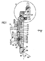
- FIG. 1 An embodiment of a tool arrangement according to the invention, shown in Fig. 1, - formed as Revolver - comprises a basic unit, designated as a whole by 10, which, for example, as rotatable about an axis 14 Carrier shaft 12 is held on a tool holder receptacle. On the base unit 10 is a holding body for tool holders 20 a tool disk 22 releasably held.
- the base unit 10 is included provided a support flange 24 which is perpendicular to one plane end face 26 lying on axis 14 and an azimuthal face around the axis 14, preferably circular cylindrical Has axis 14 formed lateral surface 28.
- the support flange 24 engages in a step-shaped Support flange receptacle 30 of the tool disc 22, which has a base 32, which is also in one plane runs perpendicular to the axis 14 and on the end face 26 of the Carrier flange 24 can be applied, and a centering surface 34 has, which rotates azimuthally about the axis 14 and preferably is designed as a circumferential surface of a circular cylinder and can be applied to the outer surface 28 of the support flange 24.
- the end face 26 and the outer surface 28 and the base surface 32 and the centering surface 34 are preferably designed such that the flange 24 in the flange receptacle 30 in the form of a fit and thus the tool disc 22 in precise alignment relative to the basic unit 10 is held.
- a holding groove 36 open towards the axis 14 arranged and in the region of a central opening 38 of the Tool disc 22 near the support flange 30 also arranged to the axis 14 open holding groove 40, wherein both holding grooves 36 and 40 in approximately the same radial Distance from the axis 14 in the base unit 10 or Rotate tool disk 22.
- Finger 50 with an inclined surface facing finger 46 54 provided which on the inclined groove wall 42 of the Holding groove 40 can be created.
- the fingers 46 and 50 are like this trained and aligned relative to each other that a press fit the finger 46 and in particular the finger 50 into the Holding grooves 36 and 40 by acting on the clamping claw body 52 pointing radially outward to the axis 14 Direction to a non-positive, non-rotating connection between the base unit 10 and the tool disk 22 leads, since the end face 26 and the base surface 32 against each other be tense.
- the clamping claws 44 are preferably one as segments Ring body with the fingers 46, 50 forming ring beads.
- the tool disc 22 on the base unit 10 via the with the support flange 24 cooperating flange mount 30 in radial direction to the axis 14 and opposite to a tilt to Axis 14 is precisely aligned and held positively, while the non-rotatable connection between the base unit 10 and the tool disc is only non-positively, so that in the event of a collision of the tool carrier within the machine tool, for example a collision of one of the tool holders 20 with other parts of the machine tool.
- the tool disc 22 opposite each other the base unit 10 due to loosening the non-positive twisted connection and thus twisted Damage in the area of the base unit 10 avoided can and after loosening the clamping screws 56 precise alignment of the rotary position of the tool disc again 22 can take place relative to the base unit 10.
- the tool disk includes the tool holder 20 22 a first support surface 70 for each tool holder 20, which lies in a plane 72, which in this case is vertical to axis 14.
- the tool disc also includes for receiving each tool holder 20 a second support surface 80, which is an annular azimuthally circumferential section around the axis 14 a lateral surface 82 of one coaxial with the axis 14 and represents radially symmetrical cone and thus in one acute angle ⁇ extends to the first support surface 70.
- a second support surface 80 which is an annular azimuthally circumferential section around the axis 14 a lateral surface 82 of one coaxial with the axis 14 and represents radially symmetrical cone and thus in one acute angle ⁇ extends to the first support surface 70.
- the first support surface 70 extends radially Direction to axis 14 up to a circular boundary line 84 about the axis 14, which lies on the cone surface 82 and also limits the second support surface 80.
- the tool holder is for each 20 the first support surface 70 divided into two in a support surface 70a and a support surface 70b, which is opposite on both sides of the support surface 70 is a recessed insertion channel 90 lie and also the second support surface 80 is through separated the insertion channel into two partial areas 80a and 80b.
- Each of the tool holders 20 now has, as in FIGS. 1, 3 and 4 shown, a first support area 100, which on the first support surface 70, in particular the two partial surfaces 70a and 70b, can be applied and a second support area 110, which is divided into two sections 110a and 110b is.
- the first support area 100 is preferably a flat surface which is provided on a tool holder housing 120 and the second support area 110 is preferably formed by an inclined surface which extends at an acute angle ⁇ to the flat surface 100 and is arranged on a nose 122 of the tool holder housing 120 and which in particular has a Section of a conical surface corresponding to the conical surface 82.
- the tool holder housing 120 with a Provided clamping body 124 which preferably one a side opposite the second support region 110 of the first support region 100 on the tool holder housing 120 is arranged, via the first support region 100 from the tool holder housing 120 protrudes away and a head 126 which has a conical shape to the tool holder housing 120 has tapering bearing surface 128.
- the clamping body 124 is, as in FIGS. 1 and 2 and again enlarged in Fig. 5 and 6, in a as Entire fixture labeled 130 can be inserted, which comprises a clamping element 132, the one to one Axis of rotation 134 has cylindrical outer surface 136 and with this cylindrical outer surface 136 in a bore 138 is seated, which extends from a rear 140 the tool disk 22 through this to the first Support surface 70 extends.
- the clamping element 132 also has one of the support surface 70 facing clamping link 142, which by one Interior 144 arranged around the axis of rotation 134 in the Locking element 132 extends around and a wedge surface 150 having a crescent shape around the interior 144 and starting from an initial region 152 of the clamping link 142 with increasing extension in azimuthal Direction around the axis of rotation 134 is increasingly smaller becoming radial distance at an end region 154 of the clamping link 142 is minimal.
- the clamping link 142 between the start region 152 and the end region 154 thereof is interrupted in the azimuthal direction and forms an insertion opening 155 for the clamping body 124, which faces the insertion channel 90 in an inserted position of the clamping element 132 and is flush with this, as the cocking guide 142 2 in Fig. 2, so that the clamping member 124 along a radial to the axis 14 insertion path 156 (represented by the introducer 90 into the interior region 144 of the clamping element 132 in connection with the clamping link 142 2 in Fig. 2) is insertable.
- the wedge surface 150 By turning the clamping element 132 from the insertion position, in which the insertion opening 155 is aligned with the insertion channel 90, in a first direction of rotation 158, the wedge surface 150, which also runs at the same angle as the contact surface 128 of the clamping body 124 conical to the axis of rotation 134, crosses the insertion path 156, comes into contact with the clamping body 124 and acts on the clamping body 124 in the direction of a clamping direction 160, shown in FIG. 6, via the bearing surface 128, the clamping link 142 with the wedge surface 150, on the one hand, the clamping body 124 in the radial direction to the axis 14 moves and on the other hand additionally pulls in the direction of the axis of rotation 134 into the locking element 132.
- the locking element 132 is also on the back 140 of the tool disk 22 protruding flats 164 provided, with which with an appropriate key the tightening element 132 acts to rotate the same can be in the clamping direction 160 on the clamping body 124 act.
- the respective tool holder is clamped with a rotation of the clamping element 132, which is preferably less than 270 °, more preferably less than 180 °.
- the Wedge surface 150 with a diminishing radial Distance from the axis of rotation 134, which corresponds to a wedge angle in a straight bend, which is smaller than a wedge angle of self-locking.
- each such tool holder station is an alignment element 172 assigned, which is preferably a circular cylindrical Has lateral surface 174.
- This alignment element 172 engages with the tool disk 22 attached tool holder housing 120 in a recess 176 of the same, which between the partial areas 110a and 110b of the second support area 110 is arranged and itself extends radially to the axis 14 to the outside.
- the recess 176 is part of an alignment device 180, which one lying on one side of the recess 176 Has set screw 182, the longitudinal axis 184 of which extends approximately azimuthal direction and that with a End face 186 on the outer surface 174 of the alignment element 172 acts.
- the set screw 182 is opposite body 190 acted upon by a compression spring 188, for example a ball is provided, which is also on the Shell surface 174 on an opposite end face 186 Side of the alignment element 172 abuts.
- the spring-loaded ball 190 thus poses when touching down the tool holder housing 120 on the support surfaces 70 and 80 sure that the face 186 is always energized the outer surface 174 of the alignment element 172 abuts and thus by adjusting the end face 186 by turning the set screw 182 the azimuthal position of the tool holder housing 120 can be precisely determined.
- the alignment element 172 preferably sits exactly symmetrically to a center line 92 of the insertion channel 90, during the Locking body 124 with the tool holder attached its central axis 129 slightly offset to the side Center line 92 and eccentric to the axis of rotation 134 of the clamping element 132 that intersects the center line 92 is to the side to which the beginning 152 the wedge surface 150 when turning the clamping element 132 to Tightening the clamping body 124 moves. With that be on the tool holder housing 120 prevents tilting moments acting, leading to an uneven concern of the second Support areas could lead to the second support surfaces.
- a tool holder 20 is now inserted in such a way that it is first attached to the tool disk 22 by a movement parallel to the axis 14 in such a way that the clamping body 124 is positioned lying in the insertion channel 90, namely between the alignment element 172 and the clamping element 132 with the Clamping link 142.
- the support area 100 of the tool holder body 120 also comes to rest on the support surfaces 70a and 70b on both sides of the insertion channel 90.
- the clamping body 124 can be moved along the insertion path 156, which runs parallel to the center line 92 of the insertion channel 90, towards the clamping link 142 2 , which is aligned in the insertion position with the insertion opening 155 so that the clamping member 142 is 2 end position 124 in one of the clamping link member in the region surrounded by the clamping link member 142 interior 144 engageable.
- the wedge surface 150 acts on the bearing surface 128 of the clamping body 124, as already described, in the clamping direction 160.
- the insertion path 156 of the clamping body 124 thus runs on the one hand in a straight direction and on the other hand essentially exactly radial to axis 14 and parallel to the plane 72, since preferably the support area 100 along the support surface 70 slides until the support area 110 on the Support surface 80 rests.
- Such a course of the insertion path is particularly advantageous 156 in a variant of the tool carrier according to the invention, which is shown in Fig. 7.
- the tool holder 20 'as such for rotating tools are formed and have one in the tool holder housing 122 rotatably mounted tool spindle 200 on, which can be driven via a gear 202, which when inserted Tool holder 20 'on an axis 14 facing Side of the tool holder housing 122 'protrudes and is driven by a crown gear 204, which around the Axis 14 rotatably supported and a separate drive driven is.
- the crown gear 204 is preferably in a tool carrier housing 210 arranged which is a cylindrical around the axis 14 has circumferential casing body 212, in which openings 214 are arranged, in which the tool holder housing 122 can be used with a cylindrical projection 216 is.
Landscapes
- Engineering & Computer Science (AREA)
- Mechanical Engineering (AREA)
- Automatic Tool Replacement In Machine Tools (AREA)
- Jigs For Machine Tools (AREA)
- Gripping On Spindles (AREA)
Description
- Fig. 1
- einen Schnitt durch einen Werkzeugträger längs Linie 1-1 in Fig. 2 bei montiertem Werkzeughalter, jedoch nicht vorhandenem Ausrichtelement;
- Fig. 2
- eine Draufsicht auf einen erfindungsgemäßen Werkzeugträger mit montiertem Werkzeughalter in Richtung des Pfeils A in Fig. 1;
- Fig. 3
- einen Schnitt durch einen Werkzeughalter längs Linie 3-3 in Fig. 4;
- Fig. 4
- eine Draufsicht auf einen Werkzeughalter in Richtung des Pfeils B in Fig. 3;
- Fig. 5
- eine vergrößerte Darstellung eines Bereichs X in Fig. 1 mit einem in einer Einsetzstellung stehendem Festspannelement;
- Fig. 6
- eine Darstellung entsprechend Fig. 5 mit einem den Werkzeughalter festspannenden Festspannelement;
- Fig. 7
- einen Schnitt ähnlich Fig. 1 durch eine Variante der erfindungsgemäßen Werkzeugträgeranordnung für rotierend angetriebene Werkzeuge.
Claims (57)
- Werkzeuganordnung für Werkzeugmaschinen umfassend einen Werkzeughalter (20) und einen Werkzeugträger mit einer Grundeinheit (10), einem an der Grundeinheit (10) angeordneten Haltekörper (22), an welchem zwei in einem spitzen Winkel zueinander verlaufende Stützflächen (70, 80) zum Abstützen das Werkzeughalters (20) in einem ersten Stützbereich (100) und einem zweiten Stützbereich (110) angeordnet sind, und einer Festspanneinrichtung (130) zum Einwirken auf einen Festspannkörper (124) des Werkzeughalters (20) in einer derart verlaufenden Spannrichtung, daß der Werkzeughalter (20) mit dem ersten (100) und dem zweiten Stützbereich (110) die Stützflächen (70, 80) beaufschlagt,
dadurch gekennzeichnet, daß
ein Festspannelement (132) der Festspanneinrichtung (130) um eine Achse (134) drehbar im Haltekörper (22) gelagert ist und eine auf einer Bahn um die Achse (134) bewegbare Keilfläche (150) zum Einwirken auf den Festspannkörper (124) trägt, und daß die Keilfläche (150) des Festspannelements (132) ausgehend von einer Einsetzstellung beim Drehen des Festspannelements (132) in einer ersten Drehrichtung (158) den Festspannkörper (124) übergreift und diesen zunehmend in der Spannrichtung (160) verschiebend beaufschlagt. - Werkzeuganordnung nach Anspruch 1, dadurch gekennzeichnet, daß das Festspannelement (132) in einem die Stützflächen (70, 80) tragenden Bereich des Haltekörpers (22) angeordnet ist.
- Werkzeuganordnung nach Anspruch 2, dadurch gekennzeichnet, daß das Festspannelement (132) auf einer dem Werkzeughalter (20) gegenüberliegenden Seite einer der Stützflächen (70) im Haltekörper (22) angeordnet ist.
- Werkzeuganordnung nach einem der voranstehenden Ansprüche,
dadurch gekennzeichnet, daß das Festspannelement (132) um eine quer zu einer der Stützflächen (70) verlaufende Achse (134) drehbar ist. - Werkzeuganordnung nach einem der voranstehenden Ansprüche,
dadurch gekennzeichnet, daß das Festspannelement (132) in einer den Haltekörper (22) durchsetzenden Bohrung (138) drehbar gelagert ist. - Werkzeuganordnung nach einem der voranstehenden Ansprüche,
dadurch gekennzeichnet, daß das Festspannelement (132) derart bewegbar ist, daß die Keilfläche (150) den Einsetzweg (156) des Festspannkörpers (124) kreuzt. - Werkzeuganordnung nach einem der voranstehenden Ansprüche,
dadurch gekennzeichnet, daß die Keilfläche (150) in der Einsetzstellung des Festspannelements (132) außerhalb eines Einsetzwegs (156) des Festspannkörpers (124) angeordnet ist, weichen dieser beim Einsetzen des Werkzeughalters (20) in den Werkzeugträger beschreibt, und daß sich die Keilfläche (150) nach Drehung des Festspannelements (132) in der ersten Richtung (158) sich mit dem den Festspannkörper (124) beaufschlagenden Bereich quer zu diesem Einsatzweg (156) erstreckt. - Werkzeuganordnung nach einem der voranstehenden Ansprüche,
dadurch gekennzeichnet, daß das Festspannelement (132) so angeordnet ist, daß es in der Lage ist, auf den in einem gegenüber einer der Stützflächen (70) vertieft im Haltekörper (22) angeordneten Einführkanal (90) einführbaren Festspannkörper (124) zu wirken. - Werkzeuganordnung nach einem der voranstehenden Ansprüche, dadurch gekennzeichnet, daß der Haltekörper (22) einen geradlinigen Einsetzweg (156) zuläßt.
- Werkzeuganordnung nach Anspruch 9, dadurch gekennzeichnet, daß der Einsetzweg (156) parallel zu einer der Stützflächen (70, 80) verläuft.
- Werkzeuganordnung nach einem der voranstehenden Ansprüche, dadurch gekennzeichnet, daß das Festspannelement (132) zum Spannen des Werkzeughalters (20) um einen Winkel von weniger als 270° drehbar ist.
- Werkzeuganordnung nach einem der voranstehenden Ansprüche, dadurch gekennzeichnet, daß das Festspannelement (132) eine die Keilfläche (150) tragende Spannkulisse (142) umfaßt.
- Werkzeuganordnung nach Anspruch 12, dadurch gekennzeichnet, daß die Spannkulisse (142) sichelförmig gebogen ist.
- Werkzeuganordnung nach Anspruch 12 oder 13, dadurch gekennzeichnet, daß das Festspannelement (132) eine vor einem Anfangsbereich (152) der Spann kulisse (142) liegende Ausnehmung (154) aufweist, durch welche der Festspannkörper (124) bei seiner Bewegung in Einsetzrichtung in den Wirkungsbereich der Spannkulisse (142) bringbar ist.
- Werkzeuganordnung nach einem der Ansprüche 12 bis 14, dadurch gekennzeichnet, daß die Spannkulisse (142) die Keilfläche (150) auf einer der Achse des Festspannelements (132) zugewandten Seite trägt.
- Werkzeuganordnung nach Anspruch 15, dadurch gekennzeichnet, daß das Festspannelement (132) einen Hohlzylinder umfaßt, welcher mit einem Wandabschnitt die Spannkulisse (142) bildet.
- Werkzeuganordnung nach einem der voranstehenden Ansprüche, dadurch gekennzeichnet, daß die Stützflächen (70,80) und das Festspannelement (132) derart relativ zueinander angeordnet sind, daß der Werkzeughalter (20) durch eine Bewegung längs eines geradlinigen Einsetzwegs (156) mit dem ersten und zweiten Stützbereich (100, 110) an den entsprechenden Stützflächen (70, 80) anlegbar und mit dem Festspannkörper (124) in den Wirkungsbereich des Festspannelements (132) bringbar ist.
- Werkzeuganordnung nach einem der voranstehenden Ansprüche, dadurch gekennzeichnet, daß eine Stützfläche (70, 80) des Haltekörpers (22) Teilflächen (70a, b; 80a, b) aufweist, die beiderseits eines sich in der Einführrichtung erstreckenden Einführkanals (90) für den Festspannkörper (124) liegen.
- Werkzeuganordnung nach Anspruch 18, dadurch gekennzeichnet, daß beide Stützflächen (70, 80) geteilt sind und jede der Stützflächert (70, 80) beiderseits des Einführkanals (90) für den Festspannkörper (124) liegende Teilflächen (70a, b; 80a, b) aufweist.
- Werkzeuganordnung nach einem der voranstehenden Ansprüche; dadurch gekennzeichnet, daß die Spannrichtung (160) parallel zu einer Richtung verläuft, die innerhalb des von den Stützflächen (70, 80) begrenzten Winkelbereichs (α) liegt.
- Werkzeuganordnung nach einem der voranstehenden Ansprüche,
dadurch gekennzeichnet, daß der Haltekörper (22) kraftschlüssig mit der Grundeinheit (10) verbunden ist. - Werkzeuganordnung nach Anspruch 21, dadurch gekennzeichnet, daß die Grundeinheit (10) und der Haltekörper (22) durch Formschlußetemente (24, 30) retativ zueinander definiert ausrichtbar sind und daß die Formschlußelemente (24, 30) gegen eine Relativbewegung-zueinander kraftschlüssig fixiert sind.
- Werkzeuganordnung nach Anspruch 21 oder 22, dadurch gekennzeichnet, daß die Grundeinheit (10) und der Haltekörper (22) durch an der Grundeinheit (10) und am Haltekörper (22) angreifende Spannpratzen (44) kraftschlüssig aneinander fixiert sind.
- Werkzeuganordnung nach Anspruch 23, dadurch gekennzeichnet, daß im Bereich mindestens einer Angriffsstelle (36, 40) der Spannpratzen (44) eine Schrägfläche (42) vorgesehen ist, durch welche die Spannpratzen (44) eine den Kraftschluß bewirkende Kraft erzeugen.
- Werkzeuganordnung nach einem der voranstehenden Ansprüche,
dadurch gekennzeichnet, daß der Grundeinheit (10) als Trägerwelle (12) und der Haltekörper als Werkzeugscheibe (22) eines Werkzeugrevolvers ausgebildet sind. - Werkzeuganordnung nach Anspruch 25, dadurch gekennzeichnet, daß die Trägerwelle (12) als Hohlwelle ausgebildet ist und daß die Spannpratzen (44) in radialer Richtung der Hohlwelle (12) wirksam sind, um die Werkzeugscheibe (22) und die Hohlwelle (12) in axialer Richtung zu verspannen.
- Werkzeuganordnung nach einem der voranstehenden Ansprüche, dadurch gekennzeichnet, daß der Werkzeughalter (20) ein Werkzeughaltergehäuse (120) aufweist, welches einen ersten und einen zweiten Stützbereich (110) aufweist, die in einem spitzen Winkel zueinander verlaufen und an entsprechenden Stützflächen (70, 80) eines Haltekörpers (22) eines Werkzeugträgers anlegbar sind, und welches einen Festspannkörper (124) trägt, auf welchen eine Festspanneinrichtung (130) des Werkzeugträgers beim Festspannen des Werkzeughalters (20) einwirkt.
- Werkzeuganordnung nach Anspruch 27, dadurch gekennzeichnet, daß der Haltekörper (22) mit einem Ausrichtelement (172) zum exakten Positionieren des Werkzeughalters (20) versehen ist und daß der Werkzeughalter (20) eine mit dem Ausrichtelement (172) in Eingriff bringbare Ausrichteinrichtung (180) aufweist.
- Werkzeuganordnung nach Anspruch 27 oder 28, dadurch gekennzeichnet, daß der Festspannkörper (124) über einen der Stützbereiche (100) vom Werkzeughaltergehäuse (120) weg übersteht.
- Werkzeuganordnung nach einem der Ansprüche 27 bis 29, dadurch gekennzeichnet, daß der Festspannkörper (124) einen Kopf (126) mit einer sich konisch zum Werkzeughattergehäuse (120) hin verjüngenden Auflagefläche (128) aufweist.
- Werkzeuganordnung nach einem der Ansprüche 27 bis 30, dadurch gekennzeichnet, daß ein erster der Stützbereiche (100) durch eine Planfläche des Werkzeughaltergehäuses (120) gebildet ist.
- Werkzeuganordnung nach einem der Ansprüche 27 bis 31, dadurch gekennzeichnet, daß der zweite Stützbereich (110) durch eine an einer Nase (122) des Werkzeughaltergehäuses (120) angeordnete Fläche gebildet ist.
- Werkzeuganordnung nach Anspruch 32, dadurch gekennzeichnet, daß der zweite Stützbereich (110) in zwei Teilbereiche geteilt ist.
- Werkzeuganordnung nach einem der Ansprüche 27 bis 33, dadurch gekennzeichnet, daß dieser mit einer Ausrichteinrichtung (180) versehen ist, welcher mit einem Ausrichtelement (172) am Werkzeugträger in Wechselwirkung bringbar ist.
- Werkzeuganordnung nach Anspruch 34, dadurch gekennzeichnet, daß die Ausrichteinrichtung (180) ein voreinstellbares Stellelement (182) umfaßt.
- Werkzeugträger für Werkzeugmaschinen umfassend eine Grundeinheit (10), einen an der Grundeinheit (10) angeordneten Haltekörper (22), an welchem zwei in einem spitzen Winkel zueinander verlaufende Stützflächen (70, 80) zum Abstützen eines Werkzeughalters (20) angeordnet sind, und eine Festspanneinrichtung (130) zum Einwirken auf den Werkzeughalter (20) in einer Spannrichtung,
dadurch gekennzeichnet, daß
ein Festspannelement (132) der Festspanneinrichtung (130) um eine Achse (134) drehbar im Haltekörper (22) gelagert ist und eine auf einer Bahn um die Achse (134) bewegbare Keilfläche (150) trägt, und daß die Keilfläche (150) des Festspannelements (132) durch eine sichelförmig gebogene Spannkulisse (142) gebildet ist. - Werkzeugträger nach Anspruch 36, dadurch gekennzeichnet, daß das Festspannelement (132) in einem die Stützflächen (70, 80) tragenden Bereich des Haltekörpers (22) angeordnet ist.
- Werkzeugträger nach Anspruch 37, dadurch gekennzeichnet, daß das Festspannelement (132) auf einer dem Werkzeughalter (20) gegenüberliegenden Seite einer der Stützflächen (70) im Haltekörper (22) angeordnet ist.
- Werkzeugträger nach einem der Ansprüche 36 bis 38, dadurch gekennzeichnet, daß das Festspannelement (132) um eine quer zu einer der Stützflächen (70) verlaufende Achse, (134) drehbar ist.
- Werkzeugträger nach einem der Ansprüche 36 bis 39, dadurch gekennzeichnet, daß das Festspannelement (132) in einer den Haltekörper (22) durchsetzenden Bohrung (138) drehbar gelagert ist.
- Werkzeugträger nach einem der Ansprüche 36 bis 40, dadurch gekennzeichnet, daß das Festspannelement (132) derart bewegbar ist, daß die Keilfläche (150) einen Einsetzweg (156) für einen Festspannkörper (124) kreuzt.
- Werkzeugträger nach einem der Ansprüche 36 bis 41, dadurch gekennzeichnet, daß die Keilfläche (150) in der Einsetzstellung des Festspannelements (132) außerhalb eines Einsetzwegs (156) angeordnet ist, und daß sich die Keilfläche (150) nach Drehung des Festspannelements (132) in der ersten Richtung (158) sich mit einem Bereich quer zu diesem Einsatzweg (156) erstreckt.
- Werkzeugträger nach Anspruch 41 oder 42, dadurch gekennzeichnet, daß der Haltekörper (22) einen geradlinigen Einsetzweg (156) zuläßt.
- Werkzeugträger nach Anspruch 43, dadurch gekennzeichnet, daß der Einsetzweg (156) parallel zu einer der Stützflächen (70, 80) verläuft.
- Werkzeugträger nach einem der Ansprüche 36 bis 44, dadurch gekennzeichnet, daß das Festspannelement (132) zum Spannen des Werkzeughalters (20) um einen Winkel von weniger als 270° drehbar ist.
- Werkzeugträger nach einem der Ansprüche 36 bis 45, dadurch gekennzeichnet, daß das Festspannelement (132) eine vor einem Anfangsbereich (152) der Spannkulisse (142) liegende Ausnehmung (154) aufweist.
- Werkzeugträger nach einem der Ansprüche 36 bis 46, dadurch gekennzeichnet, daß die Spannkulisse (142) die Keilfläche (150) auf einer der Achse des Festspannelements (132) zugewandten Seite trägt.
- Werkzeugträger nach Anspruch 47, dadurch gekennzeichnet, daß das Festspannelement (132) einen Hohlzylinder umfaßt, welcher mit einem Wandabschnitt die Spannkulisse (142) bildet.
- Werkzeugträger nach einem der Ansprüche 36 bis 48, dadurch gekennzeichnet, daß eine Stützfläche (70, 80) des Haltekörpers (22) Teilflächen (70a, b; 80a, b) aufweist, die beiderseits eines sich in der Einführrichtung erstreckenden Einführkanals (90) für einen Festspannkörper (124) liegen.
- Werkzeugträger nach Anspruch 49, dadurch gekennzeichnet, daß beide Stützflächen (70, 80) geteilt sind und jede der Stützflächen (70, 80) beiderseits des Einführkanals (90) liegende Teilflächen (70a, b; 80a, b) aufweist.
- Werkzeugträger nach einem der Ansprüche 36 bis 50, dadurch gekennzeichnet, daß die Spannrichtung (160) parallel zu einer Richtung verläuft, die innerhalb des von den Stützflächen (70, 80) begrenzten Winkelbereichs (α) liegt.
- Werkzeugträger nach einem der Ansprüche 36 bis 51, dadurch gekennzeichnet, daß der Haltekörper (22) kraftschlüssig mit der Grundeinheit (10) verbunden ist.
- Werkzeugträger nach Anspruch 52, dadurch gekennzeichnet, daß die Grundeinheit (10) und der Haltekörper (22) durch Formschlußelemente (24, 30) relativ zueinander definiert ausrichtbar sind und daß die Formschlußelemente (24, 30) gegen eine Relativbewegung zueinander kraftschlüssig fixiert sind.
- Werkzeugträger nach Anspruch 52 oder 53, dadurch gekennzeichnet, daß die Grundeinheit (10) und der Haltekörper (22) durch an der Grundeinheit (10) und am Haltekörper (22) angreifende Spannpratzen (44) kraftschlüssig aneinander fixiert sind.
- Werkzeugträger nach Anspruch 54, dadurch gekennzeichnet, daß im Bereich mindestens einer Angriffsstelle (36, 40) der Spannpratzen (44) eine Schrägfläche (42) vorgesehen ist, durch welche die Spannpratzen (44) eine den Kraftschluß bewirkende Kraft erzeugen.
- Werkzeugträger nach einem der Ansprüche 36 bis 55, dadurch gekennzeichnet, daß der Grundeinheit (10) als Trägerwelle (12) und der Haltekörper als Werkzeugscheibe (22) eines Werkzeugrevolvers ausgebildet sind.
- Werkzeugträger nach Anspruch 56, dadurch gekennzeichnet, daß die Trägerwelle (12) als Hohlwelle ausgebildet ist und daß die Spannpratzen (44) in radialer Richtung der Hohlwelle (12) wirksam sind, um die Werkzeugscheibe (22) und die Hohlwelle (12) in axialer Richtung zu verspannen.
Applications Claiming Priority (3)
| Application Number | Priority Date | Filing Date | Title |
|---|---|---|---|
| DE19919236A DE19919236A1 (de) | 1999-04-28 | 1999-04-28 | Werkzeugträger für Werkzeugmaschinen und Werkzeuganordnung für Werkzeugmaschinen |
| DE19919236 | 1999-04-28 | ||
| PCT/EP2000/003718 WO2000066303A1 (de) | 1999-04-28 | 2000-04-26 | Werkzeugträger für werkzeugmaschinen und werkzeuganordnung für werkzeugmaschinen |
Publications (2)
| Publication Number | Publication Date |
|---|---|
| EP1091820A1 EP1091820A1 (de) | 2001-04-18 |
| EP1091820B1 true EP1091820B1 (de) | 2004-06-23 |
Family
ID=7906110
Family Applications (1)
| Application Number | Title | Priority Date | Filing Date |
|---|---|---|---|
| EP00925241A Expired - Lifetime EP1091820B1 (de) | 1999-04-28 | 2000-04-26 | Werkzeugträger für werkzeugmaschinen und werkzeuganordnung für werkzeugmaschinen |
Country Status (5)
| Country | Link |
|---|---|
| US (2) | US6513410B2 (de) |
| EP (1) | EP1091820B1 (de) |
| AT (1) | ATE269770T1 (de) |
| DE (2) | DE19919236A1 (de) |
| WO (1) | WO2000066303A1 (de) |
Families Citing this family (6)
| Publication number | Priority date | Publication date | Assignee | Title |
|---|---|---|---|---|
| DE102005033890A1 (de) * | 2005-07-20 | 2007-01-25 | Sauter Feinmechanik Gmbh | Werkzeugrevolver |
| DE102005045662A1 (de) * | 2005-09-13 | 2007-03-15 | Sauter Feinmechanik Gmbh | Werkzeugrevolver |
| EP1992435B1 (de) * | 2007-05-16 | 2009-11-18 | Alps Tool Co., Ltd. | Werkzeughaltepositioniervorrichtung |
| DE102008040561A1 (de) * | 2008-07-18 | 2010-01-21 | Sandvik Intellectual Property Ab | Ausbohrwerkzeug |
| DE102011078445A1 (de) * | 2011-06-30 | 2013-01-03 | Wto Werkzeug-Einrichtungen Gmbh | Werkzeugträger mit auswechselbaren Werkzeughaltern und Werkzeughalter |
| US10399006B2 (en) | 2015-03-17 | 2019-09-03 | California Extraction Ventures, Inc. | Catalyzing pressure wave extraction method and apparatus |
Family Cites Families (9)
| Publication number | Priority date | Publication date | Assignee | Title |
|---|---|---|---|---|
| DE4028775C1 (de) | 1990-03-28 | 1991-07-25 | Ott Maschinentechnik Gmbh, 8960 Kempten, De | |
| US5507170A (en) * | 1993-05-18 | 1996-04-16 | Amada Metrecs Company, Limited | Upper tool for press brake |
| JP3262799B2 (ja) * | 1994-02-19 | 2002-03-04 | ケンナメタル ヘルテル アクチェンゲゼルシャフト ウェルクツォイゲ ウント ハルトシュトッフェ | フライス |
| DE19613377B4 (de) * | 1996-04-03 | 2006-06-22 | Traub Drehmaschinen Gmbh | Werkzeugrevolver, insbesondere für Drehmaschinen |
| US5816301A (en) * | 1997-07-30 | 1998-10-06 | Key Knife, Inc. | Knife supporting structure |
| US6003415A (en) * | 1997-09-23 | 1999-12-21 | Houston Instrument Tooling Company, Inc. | Toolholder with cam locking mechanism |
| US6230595B1 (en) * | 1998-03-20 | 2001-05-15 | Aloris Tool Technology Co., Inc. | Tool post |
| US6270293B2 (en) * | 1998-12-22 | 2001-08-07 | Kennametal Pc Inc. | Toolholder assembly |
| US6325574B1 (en) * | 2001-02-14 | 2001-12-04 | Peter J. Treige | Machining slot cutter with removable cartridges |
-
1999
- 1999-04-28 DE DE19919236A patent/DE19919236A1/de not_active Ceased
-
2000
- 2000-04-26 EP EP00925241A patent/EP1091820B1/de not_active Expired - Lifetime
- 2000-04-26 WO PCT/EP2000/003718 patent/WO2000066303A1/de not_active Ceased
- 2000-04-26 AT AT00925241T patent/ATE269770T1/de not_active IP Right Cessation
- 2000-04-26 DE DE50006875T patent/DE50006875D1/de not_active Expired - Lifetime
- 2000-12-27 US US09/749,724 patent/US6513410B2/en not_active Expired - Fee Related
-
2001
- 2001-06-29 US US09/749,724 patent/US20010039705A1/en active Granted
Also Published As
| Publication number | Publication date |
|---|---|
| DE19919236A1 (de) | 2000-11-09 |
| WO2000066303A1 (de) | 2000-11-09 |
| US20010039705A1 (en) | 2001-11-15 |
| EP1091820A1 (de) | 2001-04-18 |
| ATE269770T1 (de) | 2004-07-15 |
| US6513410B2 (en) | 2003-02-04 |
| DE50006875D1 (de) | 2004-07-29 |
Similar Documents
| Publication | Publication Date | Title |
|---|---|---|
| EP0380974B1 (de) | Schleifmaschine mit einem Adapter zum Befestigen eines Zusatzwerkzeugs | |
| EP0126432B1 (de) | Fräswerkzeug | |
| EP0141451B1 (de) | Werkzeugaufnahmevorrichtung und Werkzeugträger | |
| EP0825911A1 (de) | Profilmesserkopf | |
| DE4028775C1 (de) | ||
| DE4322409A1 (de) | Vorrichtung zur zerspanenden Bearbeitung | |
| DE19753663A1 (de) | Spannsystem zur lösbaren Verbindung zweier Teile | |
| EP0962280B1 (de) | Ausrichteinrichtung | |
| EP0275441B1 (de) | Spannvorrichtung | |
| EP0410104B1 (de) | Zerspanungswerkzeug | |
| EP0484647A1 (de) | Vorrichtung zur Herstellung von Bohrlöchern mit Hinterschneidung | |
| DE19714398A1 (de) | Einspannvorrichtung für Werkzeuge | |
| WO2000066303A1 (de) | Werkzeugträger für werkzeugmaschinen und werkzeuganordnung für werkzeugmaschinen | |
| DE3232495A1 (de) | Vorrichtung zur kuehlmittelzufuhr zu mit kuehlmittelkanaelen versehenen, rotierenden schneidwerkzeugen fuer die spanende metallbearbeitung, insbesondere bohrwerkzeuge | |
| DE3150966A1 (de) | Spannbacke | |
| EP4155015A1 (de) | Spannvorrichtung für ein werkzeug oder werkstück mit einer zugspannzange und einem kopplungselement, eine zugspannzange und ein kopplungselement | |
| DE3432942C2 (de) | ||
| DE4424095C1 (de) | Schweißvorrichtung | |
| DE20009102U1 (de) | Ausrichteinrichtung | |
| DE10042779A1 (de) | Schneidplattenhalter mit Sicherungseinrichtung sowie Stechplatte hierfür | |
| DE102021119311A1 (de) | Werkzeughalter und Werkzeughalteraufnahmeeinheit | |
| DE29810720U1 (de) | Spannbackenhalterung | |
| DE3136472A1 (de) | Spielfreie indexierungs- und verriegelungsvorrichtung | |
| DE20219369U1 (de) | Stanzwerkzeug mit Justierring | |
| DD218851A1 (de) | Werkzeughalter mit wechselbaren werkzeugeinsaetzen |
Legal Events
| Date | Code | Title | Description |
|---|---|---|---|
| PUAI | Public reference made under article 153(3) epc to a published international application that has entered the european phase |
Free format text: ORIGINAL CODE: 0009012 |
|
| 17P | Request for examination filed |
Effective date: 20010124 |
|
| AK | Designated contracting states |
Kind code of ref document: A1 Designated state(s): AT BE CH CY DE DK ES FI FR GB GR IE IT LI LU MC NL PT SE |
|
| 17Q | First examination report despatched |
Effective date: 20021122 |
|
| GRAP | Despatch of communication of intention to grant a patent |
Free format text: ORIGINAL CODE: EPIDOSNIGR1 |
|
| GRAS | Grant fee paid |
Free format text: ORIGINAL CODE: EPIDOSNIGR3 |
|
| GRAA | (expected) grant |
Free format text: ORIGINAL CODE: 0009210 |
|
| AK | Designated contracting states |
Kind code of ref document: B1 Designated state(s): AT BE CH CY DE DK ES FI FR GB GR IE IT LI LU MC NL PT SE |
|
| PG25 | Lapsed in a contracting state [announced via postgrant information from national office to epo] |
Ref country code: GB Free format text: LAPSE BECAUSE OF FAILURE TO SUBMIT A TRANSLATION OF THE DESCRIPTION OR TO PAY THE FEE WITHIN THE PRESCRIBED TIME-LIMIT Effective date: 20040623 Ref country code: NL Free format text: LAPSE BECAUSE OF FAILURE TO SUBMIT A TRANSLATION OF THE DESCRIPTION OR TO PAY THE FEE WITHIN THE PRESCRIBED TIME-LIMIT Effective date: 20040623 Ref country code: IE Free format text: LAPSE BECAUSE OF FAILURE TO SUBMIT A TRANSLATION OF THE DESCRIPTION OR TO PAY THE FEE WITHIN THE PRESCRIBED TIME-LIMIT Effective date: 20040623 Ref country code: FI Free format text: LAPSE BECAUSE OF FAILURE TO SUBMIT A TRANSLATION OF THE DESCRIPTION OR TO PAY THE FEE WITHIN THE PRESCRIBED TIME-LIMIT Effective date: 20040623 |
|
| REG | Reference to a national code |
Ref country code: GB Ref legal event code: FG4D Free format text: NOT ENGLISH |
|
| REG | Reference to a national code |
Ref country code: CH Ref legal event code: EP |
|
| REG | Reference to a national code |
Ref country code: IE Ref legal event code: FG4D Free format text: GERMAN |
|
| REF | Corresponds to: |
Ref document number: 50006875 Country of ref document: DE Date of ref document: 20040729 Kind code of ref document: P |
|
| REG | Reference to a national code |
Ref country code: CH Ref legal event code: NV Representative=s name: KIRKER & CIE SA |
|
| PG25 | Lapsed in a contracting state [announced via postgrant information from national office to epo] |
Ref country code: SE Free format text: LAPSE BECAUSE OF FAILURE TO SUBMIT A TRANSLATION OF THE DESCRIPTION OR TO PAY THE FEE WITHIN THE PRESCRIBED TIME-LIMIT Effective date: 20040923 Ref country code: DK Free format text: LAPSE BECAUSE OF FAILURE TO SUBMIT A TRANSLATION OF THE DESCRIPTION OR TO PAY THE FEE WITHIN THE PRESCRIBED TIME-LIMIT Effective date: 20040923 Ref country code: GR Free format text: LAPSE BECAUSE OF FAILURE TO SUBMIT A TRANSLATION OF THE DESCRIPTION OR TO PAY THE FEE WITHIN THE PRESCRIBED TIME-LIMIT Effective date: 20040923 |
|
| PG25 | Lapsed in a contracting state [announced via postgrant information from national office to epo] |
Ref country code: ES Free format text: LAPSE BECAUSE OF FAILURE TO SUBMIT A TRANSLATION OF THE DESCRIPTION OR TO PAY THE FEE WITHIN THE PRESCRIBED TIME-LIMIT Effective date: 20041004 |
|
| NLV1 | Nl: lapsed or annulled due to failure to fulfill the requirements of art. 29p and 29m of the patents act | ||
| GBV | Gb: ep patent (uk) treated as always having been void in accordance with gb section 77(7)/1977 [no translation filed] |
Effective date: 20040623 |
|
| ET | Fr: translation filed | ||
| REG | Reference to a national code |
Ref country code: IE Ref legal event code: FD4D |
|
| PG25 | Lapsed in a contracting state [announced via postgrant information from national office to epo] |
Ref country code: LU Free format text: LAPSE BECAUSE OF NON-PAYMENT OF DUE FEES Effective date: 20050426 Ref country code: AT Free format text: LAPSE BECAUSE OF NON-PAYMENT OF DUE FEES Effective date: 20050426 Ref country code: CY Free format text: LAPSE BECAUSE OF FAILURE TO SUBMIT A TRANSLATION OF THE DESCRIPTION OR TO PAY THE FEE WITHIN THE PRESCRIBED TIME-LIMIT Effective date: 20050426 |
|
| PLBE | No opposition filed within time limit |
Free format text: ORIGINAL CODE: 0009261 |
|
| STAA | Information on the status of an ep patent application or granted ep patent |
Free format text: STATUS: NO OPPOSITION FILED WITHIN TIME LIMIT |
|
| PG25 | Lapsed in a contracting state [announced via postgrant information from national office to epo] |
Ref country code: MC Free format text: LAPSE BECAUSE OF NON-PAYMENT OF DUE FEES Effective date: 20050430 Ref country code: BE Free format text: LAPSE BECAUSE OF NON-PAYMENT OF DUE FEES Effective date: 20050430 |
|
| 26N | No opposition filed |
Effective date: 20050324 |
|
| BERE | Be: lapsed |
Owner name: *TRAUB DREHMASCHINEN G.M.B.H. Effective date: 20050430 |
|
| BERE | Be: lapsed |
Owner name: *TRAUB DREHMASCHINEN G.M.B.H. Effective date: 20050430 |
|
| PG25 | Lapsed in a contracting state [announced via postgrant information from national office to epo] |
Ref country code: PT Free format text: LAPSE BECAUSE OF NON-PAYMENT OF DUE FEES Effective date: 20041123 |
|
| PGFP | Annual fee paid to national office [announced via postgrant information from national office to epo] |
Ref country code: DE Payment date: 20130528 Year of fee payment: 14 Ref country code: CH Payment date: 20130412 Year of fee payment: 14 |
|
| PGFP | Annual fee paid to national office [announced via postgrant information from national office to epo] |
Ref country code: FR Payment date: 20130625 Year of fee payment: 14 Ref country code: IT Payment date: 20130420 Year of fee payment: 14 |
|
| REG | Reference to a national code |
Ref country code: DE Ref legal event code: R119 Ref document number: 50006875 Country of ref document: DE |
|
| REG | Reference to a national code |
Ref country code: CH Ref legal event code: PL |
|
| REG | Reference to a national code |
Ref country code: FR Ref legal event code: ST Effective date: 20141231 |
|
| REG | Reference to a national code |
Ref country code: DE Ref legal event code: R119 Ref document number: 50006875 Country of ref document: DE Effective date: 20141101 |
|
| PG25 | Lapsed in a contracting state [announced via postgrant information from national office to epo] |
Ref country code: LI Free format text: LAPSE BECAUSE OF NON-PAYMENT OF DUE FEES Effective date: 20140430 Ref country code: DE Free format text: LAPSE BECAUSE OF NON-PAYMENT OF DUE FEES Effective date: 20141101 Ref country code: CH Free format text: LAPSE BECAUSE OF NON-PAYMENT OF DUE FEES Effective date: 20140430 |
|
| PG25 | Lapsed in a contracting state [announced via postgrant information from national office to epo] |
Ref country code: FR Free format text: LAPSE BECAUSE OF NON-PAYMENT OF DUE FEES Effective date: 20140430 |
|
| PG25 | Lapsed in a contracting state [announced via postgrant information from national office to epo] |
Ref country code: IT Free format text: LAPSE BECAUSE OF NON-PAYMENT OF DUE FEES Effective date: 20140426 |