EP1091504A1 - Radio receiver and reception timing detection method - Google Patents
Radio receiver and reception timing detection method Download PDFInfo
- Publication number
- EP1091504A1 EP1091504A1 EP00915563A EP00915563A EP1091504A1 EP 1091504 A1 EP1091504 A1 EP 1091504A1 EP 00915563 A EP00915563 A EP 00915563A EP 00915563 A EP00915563 A EP 00915563A EP 1091504 A1 EP1091504 A1 EP 1091504A1
- Authority
- EP
- European Patent Office
- Prior art keywords
- signals
- desired signal
- delay profile
- directivities
- directivity
- Prior art date
- Legal status (The legal status is an assumption and is not a legal conclusion. Google has not performed a legal analysis and makes no representation as to the accuracy of the status listed.)
- Withdrawn
Links
Images


Classifications
-
- H—ELECTRICITY
- H01—ELECTRIC ELEMENTS
- H01Q—ANTENNAS, i.e. RADIO AERIALS
- H01Q3/00—Arrangements for changing or varying the orientation or the shape of the directional pattern of the waves radiated from an antenna or antenna system
- H01Q3/26—Arrangements for changing or varying the orientation or the shape of the directional pattern of the waves radiated from an antenna or antenna system varying the relative phase or relative amplitude of energisation between two or more active radiating elements; varying the distribution of energy across a radiating aperture
- H01Q3/2605—Array of radiating elements provided with a feedback control over the element weights, e.g. adaptive arrays
-
- H—ELECTRICITY
- H01—ELECTRIC ELEMENTS
- H01Q—ANTENNAS, i.e. RADIO AERIALS
- H01Q3/00—Arrangements for changing or varying the orientation or the shape of the directional pattern of the waves radiated from an antenna or antenna system
- H01Q3/26—Arrangements for changing or varying the orientation or the shape of the directional pattern of the waves radiated from an antenna or antenna system varying the relative phase or relative amplitude of energisation between two or more active radiating elements; varying the distribution of energy across a radiating aperture
-
- H—ELECTRICITY
- H04—ELECTRIC COMMUNICATION TECHNIQUE
- H04B—TRANSMISSION
- H04B7/00—Radio transmission systems, i.e. using radiation field
- H04B7/02—Diversity systems; Multi-antenna system, i.e. transmission or reception using multiple antennas
- H04B7/04—Diversity systems; Multi-antenna system, i.e. transmission or reception using multiple antennas using two or more spaced independent antennas
- H04B7/08—Diversity systems; Multi-antenna system, i.e. transmission or reception using multiple antennas using two or more spaced independent antennas at the receiving station
- H04B7/0837—Diversity systems; Multi-antenna system, i.e. transmission or reception using multiple antennas using two or more spaced independent antennas at the receiving station using pre-detection combining
- H04B7/0842—Weighted combining
- H04B7/086—Weighted combining using weights depending on external parameters, e.g. direction of arrival [DOA], predetermined weights or beamforming
Definitions
- the present invention relates to a radio reception apparatus and a method for detecting reception timing, both being used in a digital radio communication system.
- a propagation path in a digital radio communication system has a frequency characteristic as a transmission path, and then the propagation path has a transmission characteristic having selectivity to frequencies, since the propagation path is generally composed of multipath. Moreover, these characteristics vary with time as a communication terminal such as a mobile station moves, and a received signal consequently has fading different in its frequency band. The fading is called as selective fading.
- the adaptive array technique is a technique in which a plurality of antenna elements are prepared and signals received by these antenna elements are weighted to be combined.
- FIG. 1 is a block diagram showing the schematic configuration of the adaptive array antenna device.
- the adaptive array antenna device outputs signals received by antennas 1-1 to 1-n to weighting circuits 2-1 to 2-n, respectively.
- the weighting circuits 2-1 to 2-n weight each of the signals for controlling directivity, and output the weighted signals to a combining circuit 3 for combining the weighed signals.
- the combined signal is output to a receiver 4 and a frame synchronization circuit 6.
- the receiver 4 demodulates the combined signal to output a demodulated output.
- the receiver 4 detects the received signal strength indicator (RSSI) of the combined signal to output the detected result (RSSI signal) to a weighting controller 7.
- RSSI received signal strength indicator
- the frame synchronization circuit 6 maintains the synchronization on the basis of the combined signal, and outputs the synchronization timing to the weighting controller 7.
- the weighting controller 7 controls respective weighting coefficients for outputting them to the weighting circuits 2-1 to 2-n so as to maintain the timing that the RSSI signal takes its maximum.
- the weighting coefficients are fittingly stored in a memory 8.
- a delay profile shown in FIG. 2 is generated. That is, if the device receives signals without isolating directivities in the case where a desired station and an interference station exist, signals from the desired station are received at the times "a" and "b".
- the signal at the time “a” is a signal that arrives the device directly from a direction "B".
- the signal at the time “b” is a signal that arrives the device from a direction "A” after being reflected by a far reflecting object such as a mountain. (See FIG. 5 about the directions "A” and “B”.) Consequently, the signal at the time "b” arrives the device later than the signal at the time "a”.
- signals from directions except for the direction of the desired station all become interference signals, there exist many interference signals in the case where the directivity is not isolated. When many interference signals exist, it becomes difficult to detect reception timing correctly.
- An object of the present invention is to provide a radio reception apparatus and a reception timing detection circuit, both capable of detecting the reception timing precisely at the time of detecting signals received from all directions such as a time when its power supply is turned on, and besides at the time of receiving a signal arrived from a direction different from a currently receiving direction during performing communication.
- the inventor of the present invention paid attention to the fact that all the signals from directions except for the direction, to which the directivity was generated, became interference signals when directivity reception was performed, and the fact that the interference signals made the precise detection of the reception timing difficult. And the inventor found that the interference amount in each directivity could be decreased by dispersing the interference signals by providing a plurality of fixed directivities. Consequently, those facts led the present invention.
- the subject matter of the present invention is to narrow down directions from which interference signals reach by means of delay profiles generated for each fixed directivity to suppress the interference amount of the interference signals for performing the detection of reception timing or the selection of a path.
- FIG. 3 is a block diagram showing the configuration of an adaptive array antenna device as a radio reception apparatus according to an embodiment of the present invention.
- signals are received by reception RF circuits 104-106 through antennas 101-103.
- the reception RF circuits 104-106 amplify the received signals and convert them to low frequency signals.
- the thus obtained IF signals, or base band signals are output to a directivity isolation circuit 107, and are isolated by every directivity.
- the signals isolated by every directivity are output to correlators 108-110, respectively. Incidentally, the operation of the directivity isolation circuit 107 will be described later.
- the correlators 108-110 operate the correlations between the received signals and known signals. For example, in case of a CDMA communication system, the correlators 108-110 perform despreading processing to the received signals with a spreading code and a scrambling code. In case of a TDMA communication system, the correlators 108-110 operates the correlations between known signals included in the received signals and known signals on the device side. In any cases, by performing correlation operations between the received signals and the known signals on the device side in advance, signals of a broadcasting station with which communication is desired can be extracted.
- the correlated outputs from the correlators 108-110 are output to power detection circuits 111-113, and their power is detected there.
- the detection results are output to delay profile generating circuits 114-116, and delay profiles are generated by every directivity there.
- the delay profile information is output to a determination circuit A 117, and the determination circuit A 117 determines the timing of a peak at which the reception power is largest among respective delay profiles as the reception timing. Incidentally, the generating of the delay profiles will be described later.
- the signals received by the reception RF circuits 104-106 are output to weighting circuits 118-120, respectively.
- the weighting circuits 118-120 multiply these inputted signals by a weighting coefficient to output the products of the multiplications to a combining circuit 121.
- the combining circuit 121 combines the output products to a combined signal.
- the combined signal is output to a correlator 122, and the correlation operation between the combined signal and the known signal on the device side is performed by the correlator 122, as described above.
- the correlation operation result is output to a power detection circuit 123 and a receiver 124.
- the power detection circuit 123 detects the power of the combined signal.
- the detection result is output to a delay profile generating circuit 126.
- the delay profile generating circuit 126 generates the delay profile of the detection result.
- the delay profile information is output to a determination circuit B 127, and the determination circuit B 127 determines the timing of a peak at which the reception power is largest among respective delay profiles as the reception timing. And then, the determined timing is outputted as a synchronization signal.
- the determination results of the determination circuit A 117 and the determination circuit B 127 are output to a directivity table 128.
- the directivity table 128 stores prescribed directivity patterns, and the directivity table 128 outputs a prescribed directivity pattern to the directivity isolation circuit 107 on the basis of the determination results.
- the receiver 124 demodulates the synchronized signals to output the demodulated signals. Moreover, the outputs from the receiver 124 are output to a weighting control circuit 125.
- the weighting control circuit 125 controls the weighting coefficients of the weighting circuits 118-120 so that the received signals are correctly received by means of an LMS algorithm or a CMA algorithm.
- Signals received by the reception RF circuits 104-106 through the antennas 101-103 are amplified, and their frequencies are converted by the reception RF circuits 104-106. After that, the converted signals are output to the directivity isolation circuit 107.
- the directivity isolation circuit 107 isolates the output signals by every directivity.
- a method of isolating the directivity there are methods such as a method that performs the isolation by a fast Fourier transformation (FFT) operation of the frequency-converted signals, a method that performs the isolation by multiplying the frequency-converted signals by weighting coefficients on the basis of respective directivities, and the like.
- FFT fast Fourier transformation
- a description will be given to the method that performs the isolation by multiplying the frequency-converted signals by weighting coefficients on the basis of the respective directivities as an example.
- the directivity isolation circuit 107 has a configuration as shown in FIG. 4. As shown in the FIG. 4, the output of the reception RF circuit 104 is output to the weighting circuits 201, 205 and 209. Moreover, the output of the reception RF circuit 105 is output to the weighting circuits 202, 206 and 210. Furthermore, the output of the reception RF circuit 106 is output to the weighting circuits 203, 207 and 211.
- the weighting circuits 201-203 multiply signals received by the antennas 101-103 by a weighting coefficient of an arriving direction A (see FIG. 5), respectively; the weighting circuits 205-207 multiply signals received by the antennas 101-103 by a weighting coefficient of an arriving direction B, respectively; and weighting circuits 209-211 multiply signals received by the antennas 101-103 by a weighting coefficient of an arriving direction C, respectively.
- the signals weighted by each weighting circuit are added by adders 204, 208 and 212. That is, the adder 204 adds signals that are multiplied by the weighting coefficients by the weighting circuits 201-203, and outputs a received signal in the direction A; the adder 208 adds signals that are multiplied by the weighting coefficients by the weighting circuits 205-207, and outputs a received signal in the direction B; and the adder 212 adds signals that are multiplied by the weighting coefficients by the weighting circuits 209-211, and outputs a received signal in the direction C.
- the received signals can thus be isolated by each directivity.
- the correlators 108-110 perform the correlation operations of those outputs of the received signals by each directivity, and thereby signals transmitted from a desired station are extracted. Then, the power detection circuits 111-113 detect the power of the extracted signals.
- the delay profile generating circuits 114-116 generate delay profiles by every directivity.
- the signal from a desired station 302 directly arrives the radio reception apparatus 301 from the direction B, and the signal arrives the radio reception apparatus 301 from the direction A after delay owing to the reflection from a mountain or the like. Consequently, the delay profile in the direction A, as shown in FIG. 6B, has a peak of the signal from the desired station (desired signal) at time " b".
- the delay profile in the direction B as shown in FIG. 6A, has a peak of the desired signal at time "a" (b>a).
- the desired signal is received from the direction A and the direction B, but the desired signal is not received from the direction C. That is, from the direction C, only interference signals from interference stations 303-305 are received. In this case, the delay profile becomes one as shown in FIG. 6C.
- the timing of a signal from a desired station can correctly be detected. That is, the timing of the signal from the desired station can correctly be detected by selecting a path at the time "a" in the direction B from the delay profile shown in FIG. 6A.
- the reception timing of a desired signal is detected in the method described above immediately after the power source of the device has been turned on.
- a delay profiled is generated by every directivity, and consequently the directions from which interference signals arrive are narrowed down and the interference amounts of the interference signals are suppressed.
- the detection of reception timing is performed.
- the detected timing is output to the directivity table 128.
- a weighting coefficient corresponding to the directivities elected from the directivity table 128 is output to the weighting control circuit 125.
- the weighting control circuit 125 controls the weighting circuits 118-120 so that the weighting circuits 118-120 multiply signals received by respective antennas 101-103 by the weighting coefficient.
- the signals multiplied by the weighting coefficient are combined by the combining circuit 121, and the correlation operation of the combined signal is performed by the correlator 122, namely the signal from the desired station is extracted. After that, the extracted signal is output to the receiver 124.
- the receiver 124 demodulates the combined signal to obtain a demodulated signal.
- the output from the receiver 124 is output to the weighting control circuit 125.
- the weighting control circuit 125 controls the weighting coefficients of the weighting circuits 118-120 so that the received signals are correctly received by means of an LMS algorithm or a CMA algorithm. Reception directivity is thus formed.
- the device of the present invention receives signals through a plurality of fixed directivities in a state that the timing of the received signals is not known at the time immediately after the start of receiving such as the time immediately after the turning on of the power source of the device, and the device generates a delay profile by every directivity. Because the device thus detects the reception timing (establishes synchronization) under a state of suppressing interference signals, the device can rapidly detect the reception timing even in a case where there are many interference signals or noises, differently from the conventional method for detecting reception timing where the reception timing and the reception directivity are simultaneously detected.
- a reception weighting coefficient of the adaptive array antenna can be calculated more rapidly.
- a delay profile is generated by every directivity over all directions. Then, the timing and the direction that the delay profiles become the maximum are detected. The timing and the direction are the results of the path search, and they are output to the determination circuit B 127 as the timing of the path of a presently communicating desired station.
- a signal from a desired station is extracted from signals received by the reception RF circuits 104-106, and the power detection circuit 123 detects its power to send the detected result to the delay profile generating circuit 126.
- the delay profile generating circuit 126 measures received power at every received time. Then, the delay profile generating circuit 126 extracts a path having a possibility of being the signal of the desired station on the basis of the result of the measurement of power. Thus, it is monitored whether a new arrived signal has appeared or not.
- the delay profile information (the timing of the symbol discrimination point of a receiver) is output to the determination circuit B 127.
- the determination circuit B 127 compares a new path determined by the determination circuit A and the path from the delay profile making up circuit 126. Then, if the arriving directions of the two paths are almost the same and the arrived times of them are also almost the same, the processing about the path until now is continued. On the other hand, if the arriving directions of the two paths are different from each other and the reception power of a new path is larger than that from the delay profile generating circuit 126, the path is changed to the new one. That is, the synchronization is set at the timing detected by the delay profile generating circuit 126, and the path of the timing is traced. Incidentally, in a system where a plurality of paths are combined in conformity with a RAKE combining such as the CDMA receiving system, a path having the minimum power until now is changed with a new path.
- the most suitable weighting coefficient can be calculated rapidly even at the time of changing a path.
- the radio reception apparatus and the method for detecting reception timing according to the embodiment can be applied to a base station apparatus performing radio communication with a communication terminal in a digital radio communication system.
- the reception timing can be detected correctly in a digital radio communication system even at the time of detecting a received signal from all directions such as the time of turning on the power or in case of receiving a signal arrived from a direction different from the receiving directivity during communicating.
- the present invention is not restricted to the aforesaid embodiment, and can be implemented with various variations.
- the description is given to a case where received signals are isolated to three directivities.
- the received signals may be isolated to two directivities, or four or more directivities.
- a radio reception apparatus and a method for detecting reception timing according to the present invention can suppress interference signals to select the most suitable path by using a plurality of directivities for generating a delay profile by every directivity.
- the radio reception apparatus and the method for detecting reception timing according to the present invention can take synchronization at the time of turning on its power source earlier than a conventional adaptive array antenna by combining them with an adaptive array antenna receiver. Moreover, the apparatus and the method can obtain the most suitable weighting coefficient earlier than a conventional adaptive array antenna by using the directivity information of a selected path as an initial value of a weighting control circuit of the adaptive array antenna.
- the apparatus and the method can generate delay profiles in a state that the interference signals from all directions are suppressed by combining them with an adaptive array antenna receiver, and thereby the apparatus and the method can select the most suitable path in comparison with paths until now. Moreover, the apparatus and the method can obtain the most suitable weighting coefficient earlier than a conventional adaptive array antenna by using the directivity information of a selected path as an initial value of a weighting control circuit of the adaptive array antenna.
- the present invention can be applied to a base station apparatus and a communication terminal in a digital radio communication system.
Landscapes
- Engineering & Computer Science (AREA)
- Computer Networks & Wireless Communication (AREA)
- Signal Processing (AREA)
- Radio Transmission System (AREA)
- Mobile Radio Communication Systems (AREA)
- Variable-Direction Aerials And Aerial Arrays (AREA)
Abstract
A radio reception apparatus receives signals from
all directions through a plurality of directivities, and
generates a delay profile to each directivity. The
apparatus selects a path having the largest received
signal among a plurality of delay profiles generated by
suppressing interference signals after thus narrowing
down directions.
Description
- The present invention relates to a radio reception apparatus and a method for detecting reception timing, both being used in a digital radio communication system.
- A propagation path in a digital radio communication system has a frequency characteristic as a transmission path, and then the propagation path has a transmission characteristic having selectivity to frequencies, since the propagation path is generally composed of multipath. Moreover, these characteristics vary with time as a communication terminal such as a mobile station moves, and a received signal consequently has fading different in its frequency band. The fading is called as selective fading.
- As a measure against the selective fading, there is an adaptive array technique. The adaptive array technique is a technique in which a plurality of antenna elements are prepared and signals received by these antenna elements are weighted to be combined.
- In such an adaptive array technique, reception timing is detected for receiving a desired signal correctly. An adaptive array antenna device having a reception timing detection function as a conventional radio reception apparatus is disclosed in Japanese laid-open patent publication HEI 10-51221. FIG. 1 is a block diagram showing the schematic configuration of the adaptive array antenna device.
- The adaptive array antenna device outputs signals received by antennas 1-1 to 1-n to weighting circuits 2-1 to 2-n, respectively. The weighting circuits 2-1 to 2-n weight each of the signals for controlling directivity, and output the weighted signals to a combining circuit 3 for combining the weighed signals.
- The combined signal is output to a receiver 4 and a frame synchronization circuit 6. The receiver 4 demodulates the combined signal to output a demodulated output. Moreover, the receiver 4 detects the received signal strength indicator (RSSI) of the combined signal to output the detected result (RSSI signal) to a weighting controller 7.
- Furthermore, the frame synchronization circuit 6 maintains the synchronization on the basis of the combined signal, and outputs the synchronization timing to the weighting controller 7. The weighting controller 7 controls respective weighting coefficients for outputting them to the weighting circuits 2-1 to 2-n so as to maintain the timing that the RSSI signal takes its maximum. The weighting coefficients are fittingly stored in a
memory 8. - However, in the conventional adaptive array antenna device, a delay profile shown in FIG. 2 is generated. That is, if the device receives signals without isolating directivities in the case where a desired station and an interference station exist, signals from the desired station are received at the times "a" and "b". The signal at the time "a" is a signal that arrives the device directly from a direction "B". The signal at the time "b" is a signal that arrives the device from a direction "A" after being reflected by a far reflecting object such as a mountain. (See FIG. 5 about the directions "A" and "B".) Consequently, the signal at the time "b" arrives the device later than the signal at the time "a". In this case, because signals from directions except for the direction of the desired station all become interference signals, there exist many interference signals in the case where the directivity is not isolated. When many interference signals exist, it becomes difficult to detect reception timing correctly.
- Moreover, in the case where the directivity is not isolated, signals arrived from directions other than the directivity formed by the weighting circuits 2-1 to 2-n cannot be received. Furthermore, at the time of turning on its power or in case of detecting signals received from all directions, the weighting control takes very long time.
- An object of the present invention is to provide a radio reception apparatus and a reception timing detection circuit, both capable of detecting the reception timing precisely at the time of detecting signals received from all directions such as a time when its power supply is turned on, and besides at the time of receiving a signal arrived from a direction different from a currently receiving direction during performing communication.
- The inventor of the present invention paid attention to the fact that all the signals from directions except for the direction, to which the directivity was generated, became interference signals when directivity reception was performed, and the fact that the interference signals made the precise detection of the reception timing difficult. And the inventor found that the interference amount in each directivity could be decreased by dispersing the interference signals by providing a plurality of fixed directivities. Consequently, those facts led the present invention.
- That is, the subject matter of the present invention is to narrow down directions from which interference signals reach by means of delay profiles generated for each fixed directivity to suppress the interference amount of the interference signals for performing the detection of reception timing or the selection of a path.
-
- FIG. 1 is a block diagram showing the configuration of a conventional radio reception apparatus;
- FIG. 2 is a drawing showing a delay profile generated in the conventional radio reception apparatus;
- FIG. 3 is a block diagram showing the configuration of a radio reception apparatus according to an embodiment of the present invention;
- FIG. 4 is a block diagram showing the configuration of the directivity isolation circuit of the radio reception apparatus of the embodiment;
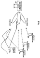
- FIG. 5 is a schematic diagram showing a communication system including the radio reception apparatus of the embodiment;
- FIG. 6A is a diagram showing a delay profile generated in the radio reception apparatus of the embodiment;
- FIG. 6B is a diagram showing another delay profile generated in the radio reception apparatus of the embodiment; and
- FIG. 6C is a diagram showing a further delay profile generated in the radio reception apparatus of the embodiment.
-
- Hereafter, an embodiment of the present invention will be described in detail with reference to the attached drawings.
- FIG. 3 is a block diagram showing the configuration of an adaptive array antenna device as a radio reception apparatus according to an embodiment of the present invention.
- In the adaptive array antenna device, signals are received by reception RF circuits 104-106 through antennas 101-103. The reception RF circuits 104-106 amplify the received signals and convert them to low frequency signals. The thus obtained IF signals, or base band signals, are output to a
directivity isolation circuit 107, and are isolated by every directivity. The signals isolated by every directivity are output to correlators 108-110, respectively. Incidentally, the operation of thedirectivity isolation circuit 107 will be described later. - The correlators 108-110 operate the correlations between the received signals and known signals. For example, in case of a CDMA communication system, the correlators 108-110 perform despreading processing to the received signals with a spreading code and a scrambling code. In case of a TDMA communication system, the correlators 108-110 operates the correlations between known signals included in the received signals and known signals on the device side. In any cases, by performing correlation operations between the received signals and the known signals on the device side in advance, signals of a broadcasting station with which communication is desired can be extracted.
- The correlated outputs from the correlators 108-110 are output to power detection circuits 111-113, and their power is detected there. The detection results are output to delay profile generating circuits 114-116, and delay profiles are generated by every directivity there. The delay profile information is output to a
determination circuit A 117, and thedetermination circuit A 117 determines the timing of a peak at which the reception power is largest among respective delay profiles as the reception timing. Incidentally, the generating of the delay profiles will be described later. - On the other hand, the signals received by the reception RF circuits 104-106 are output to weighting circuits 118-120, respectively. The weighting circuits 118-120 multiply these inputted signals by a weighting coefficient to output the products of the multiplications to a combining
circuit 121. The combiningcircuit 121 combines the output products to a combined signal. The combined signal is output to acorrelator 122, and the correlation operation between the combined signal and the known signal on the device side is performed by thecorrelator 122, as described above. The correlation operation result is output to apower detection circuit 123 and areceiver 124. - The
power detection circuit 123 detects the power of the combined signal. The detection result is output to a delayprofile generating circuit 126. The delayprofile generating circuit 126 generates the delay profile of the detection result. The delay profile information is output to adetermination circuit B 127, and thedetermination circuit B 127 determines the timing of a peak at which the reception power is largest among respective delay profiles as the reception timing. And then, the determined timing is outputted as a synchronization signal. - Incidentally, the determination results of the
determination circuit A 117 and thedetermination circuit B 127 are output to a directivity table 128. The directivity table 128 stores prescribed directivity patterns, and the directivity table 128 outputs a prescribed directivity pattern to thedirectivity isolation circuit 107 on the basis of the determination results. - The
receiver 124 demodulates the synchronized signals to output the demodulated signals. Moreover, the outputs from thereceiver 124 are output to aweighting control circuit 125. Theweighting control circuit 125 controls the weighting coefficients of the weighting circuits 118-120 so that the received signals are correctly received by means of an LMS algorithm or a CMA algorithm. - Next, the operation of the adaptive array antenna device having the aforesaid configuration will be described. At first, there will be given a description to a case of receiving a signal arrived from a direction other than the directivity pattern formed by the weighting circuits 118-120.
- Signals received by the reception RF circuits 104-106 through the antennas 101-103 are amplified, and their frequencies are converted by the reception RF circuits 104-106. After that, the converted signals are output to the
directivity isolation circuit 107. Thedirectivity isolation circuit 107 isolates the output signals by every directivity. - As a method of isolating the directivity, there are methods such as a method that performs the isolation by a fast Fourier transformation (FFT) operation of the frequency-converted signals, a method that performs the isolation by multiplying the frequency-converted signals by weighting coefficients on the basis of respective directivities, and the like. In this embodiment, a description will be given to the method that performs the isolation by multiplying the frequency-converted signals by weighting coefficients on the basis of the respective directivities as an example.
- The
directivity isolation circuit 107 has a configuration as shown in FIG. 4. As shown in the FIG. 4, the output of thereception RF circuit 104 is output to theweighting circuits reception RF circuit 105 is output to theweighting circuits reception RF circuit 106 is output to theweighting circuits - The weighting circuits 201-203 multiply signals received by the antennas 101-103 by a weighting coefficient of an arriving direction A (see FIG. 5), respectively; the weighting circuits 205-207 multiply signals received by the antennas 101-103 by a weighting coefficient of an arriving direction B, respectively; and weighting circuits 209-211 multiply signals received by the antennas 101-103 by a weighting coefficient of an arriving direction C, respectively.
- The signals weighted by each weighting circuit are added by
adders adder 204 adds signals that are multiplied by the weighting coefficients by the weighting circuits 201-203, and outputs a received signal in the direction A; theadder 208 adds signals that are multiplied by the weighting coefficients by the weighting circuits 205-207, and outputs a received signal in the direction B; and theadder 212 adds signals that are multiplied by the weighting coefficients by the weighting circuits 209-211, and outputs a received signal in the direction C. The received signals can thus be isolated by each directivity. - The correlators 108-110 perform the correlation operations of those outputs of the received signals by each directivity, and thereby signals transmitted from a desired station are extracted. Then, the power detection circuits 111-113 detect the power of the extracted signals.
- After the power has thus been detected, the delay profile generating circuits 114-116 generate delay profiles by every directivity. As shown in FIG. 5, in the case where the present
radio reception apparatus 301 receives signals through a plurality of directivities A-C, the signal from a desiredstation 302 directly arrives theradio reception apparatus 301 from the direction B, and the signal arrives theradio reception apparatus 301 from the direction A after delay owing to the reflection from a mountain or the like. Consequently, the delay profile in the direction A, as shown in FIG. 6B, has a peak of the signal from the desired station (desired signal) at time "b". The delay profile in the direction B, as shown in FIG. 6A, has a peak of the desired signal at time "a" (b>a). - As known from FIG. 5, the desired signal is received from the direction A and the direction B, but the desired signal is not received from the direction C. That is, from the direction C, only interference signals from interference stations 303-305 are received. In this case, the delay profile becomes one as shown in FIG. 6C.
- As known from FIG. 5, because the directivities are isolated, signals received from the interference stations 303-305 are narrowed down to the signal arrived from each arriving direction, respectively. The interference amounts concerning the interference signals are consequently decreased. This fact is apparent from the electric power of the interference signals in the delay profiles shown in FIGs. 6A-6C. In other words, because a delay profile is generated by every directivity, the interference amount (interference power) of an interference signal in the delay profile shown in FIG. 2 is distributed to each directivity, and consequently the interference amount in each delay profile concerning each directivity is decreased.
- As a result, in the delay profile, the timing of a signal from a desired station can correctly be detected. That is, the timing of the signal from the desired station can correctly be detected by selecting a path at the time "a" in the direction B from the delay profile shown in FIG. 6A.
- As described above, by generating a delay profile by every directivity, directions from which interference signals arrive are narrowed down, and then the interference amount of the interference signals is suppressed to make it possible to detect the reception timing. Accordingly, by setting directivity to all directions (360°) in advance, the timing of received signals concerning all directions can be detected in the state of suppressing the interference signals.
- Next, a description will be given to the operation during the communication of the adaptive array antenna device in the
embodiment 1. - The reception timing of a desired signal is detected in the method described above immediately after the power source of the device has been turned on. As described above, in the device of the present invention, a delay profiled is generated by every directivity, and consequently the directions from which interference signals arrive are narrowed down and the interference amounts of the interference signals are suppressed. Thus, the detection of reception timing is performed.
- Next, the detected timing (determination result) is output to the directivity table 128. A weighting coefficient corresponding to the directivities elected from the directivity table 128 is output to the
weighting control circuit 125. Theweighting control circuit 125 controls the weighting circuits 118-120 so that the weighting circuits 118-120 multiply signals received by respective antennas 101-103 by the weighting coefficient. The signals multiplied by the weighting coefficient are combined by the combiningcircuit 121, and the correlation operation of the combined signal is performed by thecorrelator 122, namely the signal from the desired station is extracted. After that, the extracted signal is output to thereceiver 124. - The
receiver 124 demodulates the combined signal to obtain a demodulated signal. The output from thereceiver 124 is output to theweighting control circuit 125. Theweighting control circuit 125 controls the weighting coefficients of the weighting circuits 118-120 so that the received signals are correctly received by means of an LMS algorithm or a CMA algorithm. Reception directivity is thus formed. - As described above, the device of the present invention receives signals through a plurality of fixed directivities in a state that the timing of the received signals is not known at the time immediately after the start of receiving such as the time immediately after the turning on of the power source of the device, and the device generates a delay profile by every directivity. Because the device thus detects the reception timing (establishes synchronization) under a state of suppressing interference signals, the device can rapidly detect the reception timing even in a case where there are many interference signals or noises, differently from the conventional method for detecting reception timing where the reception timing and the reception directivity are simultaneously detected.
- Furthermore, because the setting of an initial value can rapidly performed by setting a weighting coefficient corresponding to the directivity at the timing detected immediately after the start of receiving as the initial value of the adaptive array antenna, a reception weighting coefficient of the adaptive array antenna can be calculated more rapidly.
- Next, a description will be given to the operation of a change of a path during the communication of the adaptive array antenna device in the
embodiment 1. - Even during the communication, an arriving direction and an arrived time vary owing to the movement of a transmitter side. Even the conventional apparatus can follow slow variations of the arriving direction and the arrived time. However, the conventional apparatus that updates a previous slot weighting coefficient cannot follow the disappearance of an arrived signal and the appearance of a new arrived signal. Hereafter, a method capable of following the disappearance of an arrived signal and the appearance of a new arrived signal will be described.
- At first, at the time immediately after the turn on of the power source of the device, as described above, signals are first received through a plurality of fixed directivities, and a delay profile is generated to each directivity, and then a path is selected. After that, a weighting coefficient corresponding to the directivity to which the path has been selected is used as an initial value of the weighting coefficient of the adaptive array antenna.
- During the communication, as described about the
embodiment 1, a delay profile is generated by every directivity over all directions. Then, the timing and the direction that the delay profiles become the maximum are detected. The timing and the direction are the results of the path search, and they are output to thedetermination circuit B 127 as the timing of the path of a presently communicating desired station. - At the same time, as described about the
embodiment 2, a signal from a desired station is extracted from signals received by the reception RF circuits 104-106, and thepower detection circuit 123 detects its power to send the detected result to the delayprofile generating circuit 126. - The delay
profile generating circuit 126 measures received power at every received time. Then, the delayprofile generating circuit 126 extracts a path having a possibility of being the signal of the desired station on the basis of the result of the measurement of power. Thus, it is monitored whether a new arrived signal has appeared or not. The delay profile information (the timing of the symbol discrimination point of a receiver) is output to thedetermination circuit B 127. - The
determination circuit B 127 compares a new path determined by the determination circuit A and the path from the delay profile making upcircuit 126. Then, if the arriving directions of the two paths are almost the same and the arrived times of them are also almost the same, the processing about the path until now is continued. On the other hand, if the arriving directions of the two paths are different from each other and the reception power of a new path is larger than that from the delayprofile generating circuit 126, the path is changed to the new one. That is, the synchronization is set at the timing detected by the delayprofile generating circuit 126, and the path of the timing is traced. Incidentally, in a system where a plurality of paths are combined in conformity with a RAKE combining such as the CDMA receiving system, a path having the minimum power until now is changed with a new path. - Thus, by generating a delay profile by every directivity in the detection of the reception timing, directions from which interference signals arrive is narrowed down, and the interference amounts of the interference signals are suppressed for detecting the reception timing. Consequently, path search can rapidly be performed. Therefore, by continuing detecting paths from all directions even during communicating, the trace of a path of a desired station can be performed even in the case where the disappearance of arriving signals or the appearance of a new arriving signal happen.
- Furthermore, by setting the directivity information of a selected path as an initial value of the weighting control circuit, the most suitable weighting coefficient can be calculated rapidly even at the time of changing a path.
- The radio reception apparatus and the method for detecting reception timing according to the embodiment can be applied to a base station apparatus performing radio communication with a communication terminal in a digital radio communication system.
- Thereby, the reception timing can be detected correctly in a digital radio communication system even at the time of detecting a received signal from all directions such as the time of turning on the power or in case of receiving a signal arrived from a direction different from the receiving directivity during communicating.
- The present invention is not restricted to the aforesaid embodiment, and can be implemented with various variations. For example, in the embodiment, the description is given to a case where received signals are isolated to three directivities. However, the received signals may be isolated to two directivities, or four or more directivities.
- As described above, a radio reception apparatus and a method for detecting reception timing according to the present invention can suppress interference signals to select the most suitable path by using a plurality of directivities for generating a delay profile by every directivity.
- Furthermore, the radio reception apparatus and the method for detecting reception timing according to the present invention can take synchronization at the time of turning on its power source earlier than a conventional adaptive array antenna by combining them with an adaptive array antenna receiver. Moreover, the apparatus and the method can obtain the most suitable weighting coefficient earlier than a conventional adaptive array antenna by using the directivity information of a selected path as an initial value of a weighting control circuit of the adaptive array antenna.
- Furthermore, the apparatus and the method can generate delay profiles in a state that the interference signals from all directions are suppressed by combining them with an adaptive array antenna receiver, and thereby the apparatus and the method can select the most suitable path in comparison with paths until now. Moreover, the apparatus and the method can obtain the most suitable weighting coefficient earlier than a conventional adaptive array antenna by using the directivity information of a selected path as an initial value of a weighting control circuit of the adaptive array antenna.
- This application is based on the Japanese Patent Application No. HEI 11-115765 filed on April 23, 1999, entire content of which is expressly incorporated by reference herein.
- The present invention can be applied to a base station apparatus and a communication terminal in a digital radio communication system.
Claims (10)
- A radio reception apparatus comprising:receiving means for receiving signals in a plurality of fixed directivities;making up means for generating a delay profile by each of the plurality of directivities concerning a desired signal extracted from the signals, andtiming detecting means for detecting reception timing of the desired signal on a basis of the delay profile.
- The radio reception apparatus according to claim 1, wherein said apparatus divides all directions into said plurality of directivities.
- The radio reception apparatus according to claim 1, said apparatus further comprising directivity forming means for forming reception directivities of said signals.
- The radio reception apparatus according to claim 1, wherein said apparatus sets a directivity at timing detected by said timing detecting means as an initial directivity immediately after a start of receiving.
- A radio reception apparatus comprising:first delay profile generating means for extracting a desired signal by each of signals received in a plurality of fixed directivities to generate a first delay profile by each of the fixed directivities concerning the desired signal;second delay profile making up means for making up a second delay profile concerning the desired signal extracted from signals received in a variable directivity, andpath selecting means for selecting a most suitable path as to the desired signal from paths as to the desired signal detected by using said first and said second delay profiles respectively.
- A base station apparatus equipped with a radio reception apparatus, wherein said radio reception apparatus comprising:receiving means for receiving signals in a plurality of fixed directivities;generating means for making up a delay profile by each of the plurality of directivities concerning a desired signal extracted from the signals, andtiming detecting means for detecting reception timing of the desired signal on a basis of the delay profile.
- A communication terminal for performing radio communication with a base station apparatus equipped with a radio reception apparatus, wherein said radio reception apparatus comprising:receiving means for receiving signals in a plurality of fixed directivities;generating means for generating a delay profile by each of the plurality of directivities concerning a desired signal extracted from the signals, andtiming detecting means for detecting reception timing of the desired signal on a basis of the delay profile.
- A method for detecting reception timing comprising the steps of:receiving signals in a plurality of fixed directivities being set by dividing all directions;generating a delay profile by each of the plurality of directivities concerning a desired signal extracted from the signals, anddetecting the reception timing of the desired signal on a basis of the delay profile.
- The method according to claim 8, said method further comprising a step of:setting a directivity at said detected timing as an initial directivity immediately after a start of receiving.
- A method for detecting reception timing, said method comprising the steps of:extracting a desired signal by each of signals received in a plurality of fixed directivities to generate a first delay profile by each of the fixed directivities concerning the desired signal;generating a second delay profile concerning the desired signal extracted from signals received through a variable directivity, andselecting a most suitable path as to the desired signal from paths as to the desired signal detected by using said first and said second delay profiles respectively.
Applications Claiming Priority (3)
| Application Number | Priority Date | Filing Date | Title |
|---|---|---|---|
| JP11576599 | 1999-04-23 | ||
| JP11115765A JP2000307489A (en) | 1999-04-23 | 1999-04-23 | Radio receiver, and method for detecting reception timing |
| PCT/JP2000/002499 WO2000065750A1 (en) | 1999-04-23 | 2000-04-18 | Radio receiver and reception timing detection method |
Publications (1)
| Publication Number | Publication Date |
|---|---|
| EP1091504A1 true EP1091504A1 (en) | 2001-04-11 |
Family
ID=14670503
Family Applications (1)
| Application Number | Title | Priority Date | Filing Date |
|---|---|---|---|
| EP00915563A Withdrawn EP1091504A1 (en) | 1999-04-23 | 2000-04-18 | Radio receiver and reception timing detection method |
Country Status (6)
| Country | Link |
|---|---|
| US (1) | US6498928B1 (en) |
| EP (1) | EP1091504A1 (en) |
| JP (1) | JP2000307489A (en) |
| CN (1) | CN1124703C (en) |
| AU (1) | AU3680500A (en) |
| WO (1) | WO2000065750A1 (en) |
Cited By (1)
| Publication number | Priority date | Publication date | Assignee | Title |
|---|---|---|---|---|
| EP1739855A2 (en) * | 2005-06-27 | 2007-01-03 | NEC Corporation | Transmitter-receiver of mobile communication system |
Families Citing this family (18)
| Publication number | Priority date | Publication date | Assignee | Title |
|---|---|---|---|---|
| JP2001203620A (en) | 2000-01-19 | 2001-07-27 | Matsushita Electric Ind Co Ltd | Wireless base station device and wireless communication method |
| CA2323164A1 (en) * | 2000-10-11 | 2002-04-11 | Ramesh Mantha | Method, system and apparatus for improving reception in multiple access communication systems |
| WO2002052751A1 (en) * | 2000-12-25 | 2002-07-04 | Sanyo Electric Co., Ltd. | Radio device with transmission directivity, and control method and control program for the radio device |
| US7062273B2 (en) | 2000-12-25 | 2006-06-13 | Kabushiki Kaisha Toshiba | Mobile communication terminal apparatus having an array antenna for communication to at least one base station |
| JP3838877B2 (en) * | 2001-01-15 | 2006-10-25 | 日本電気株式会社 | CDMA receiver for performing path search, path search method, and program |
| JP4081982B2 (en) * | 2001-01-30 | 2008-04-30 | 日本電気株式会社 | CDMA mobile communication demodulation circuit and demodulation method |
| JP3498796B2 (en) * | 2001-03-30 | 2004-02-16 | 日本電気株式会社 | Array antenna receiver |
| JP3601598B2 (en) | 2001-05-11 | 2004-12-15 | 日本電気株式会社 | Adaptive antenna receiver |
| JP3897564B2 (en) * | 2001-10-24 | 2007-03-28 | 松下電器産業株式会社 | Radio base station apparatus and radio communication method |
| JP3955249B2 (en) * | 2002-09-13 | 2007-08-08 | 京セラ株式会社 | Array antenna system, directivity control method thereof, and mobile terminal |
| US8144824B2 (en) * | 2005-03-10 | 2012-03-27 | Qualcomm Incorporated | Trend influenced time tracking |
| US20060221810A1 (en) * | 2005-03-10 | 2006-10-05 | Bojan Vrcelj | Fine timing acquisition |
| US20100157833A1 (en) * | 2005-03-10 | 2010-06-24 | Qualcomm Incorporated | Methods and systems for improved timing acquisition for varying channel conditions |
| US8675631B2 (en) * | 2005-03-10 | 2014-03-18 | Qualcomm Incorporated | Method and system for achieving faster device operation by logical separation of control information |
| JP4583265B2 (en) * | 2005-07-21 | 2010-11-17 | 富士通株式会社 | Wireless communication apparatus and wireless communication method |
| US7623607B2 (en) * | 2005-10-31 | 2009-11-24 | Qualcomm Incorporated | Methods and apparatus for determining timing in a wireless communication system |
| US8948329B2 (en) * | 2005-12-15 | 2015-02-03 | Qualcomm Incorporated | Apparatus and methods for timing recovery in a wireless transceiver |
| CN104467911A (en) * | 2013-09-18 | 2015-03-25 | 联想(北京)有限公司 | Antenna mode adjustment method, antenna mode adjustment device and mobile terminal |
Family Cites Families (10)
| Publication number | Priority date | Publication date | Assignee | Title |
|---|---|---|---|---|
| JP2556279B2 (en) * | 1993-12-14 | 1996-11-20 | 日本電気株式会社 | Radio link control method for mobile communication system |
| FI105430B (en) * | 1995-05-24 | 2000-08-15 | Nokia Networks Oy | Base station equipment and method for directing antenna beam |
| FI98172C (en) * | 1995-05-24 | 1997-04-25 | Nokia Telecommunications Oy | Method for transmitting a pilot signal and a cellular radio system |
| JP3272961B2 (en) | 1996-08-02 | 2002-04-08 | 株式会社日立国際電気 | Adaptive array antenna |
| JP3526196B2 (en) * | 1997-01-07 | 2004-05-10 | 株式会社東芝 | Adaptive antenna |
| JP2919414B2 (en) * | 1997-01-14 | 1999-07-12 | 株式会社ワイ・アール・ピー移動通信基盤技術研究所 | Multi-path characteristics measurement method and receiver |
| JP2000059278A (en) * | 1998-08-03 | 2000-02-25 | Matsushita Electric Ind Co Ltd | Radio communication equipment |
| JP4040768B2 (en) * | 1998-10-27 | 2008-01-30 | 東芝テック株式会社 | Antenna directivity control system |
| JP3589879B2 (en) * | 1998-11-26 | 2004-11-17 | 松下電器産業株式会社 | Radio base station apparatus and transmission power control method |
| US6320853B1 (en) * | 1999-09-27 | 2001-11-20 | Metawave Communications Corporation | Method of phase recovery in cellular communication systems |
-
1999
- 1999-04-23 JP JP11115765A patent/JP2000307489A/en not_active Withdrawn
-
2000
- 2000-04-18 US US09/720,355 patent/US6498928B1/en not_active Expired - Fee Related
- 2000-04-18 EP EP00915563A patent/EP1091504A1/en not_active Withdrawn
- 2000-04-18 WO PCT/JP2000/002499 patent/WO2000065750A1/en not_active Application Discontinuation
- 2000-04-18 AU AU36805/00A patent/AU3680500A/en not_active Abandoned
- 2000-04-18 CN CN00800637.7A patent/CN1124703C/en not_active Expired - Fee Related
Non-Patent Citations (1)
| Title |
|---|
| See references of WO0065750A1 * |
Cited By (2)
| Publication number | Priority date | Publication date | Assignee | Title |
|---|---|---|---|---|
| EP1739855A2 (en) * | 2005-06-27 | 2007-01-03 | NEC Corporation | Transmitter-receiver of mobile communication system |
| EP1739855A3 (en) * | 2005-06-27 | 2007-11-07 | NEC Corporation | Transmitter-receiver of mobile communication system |
Also Published As
| Publication number | Publication date |
|---|---|
| AU3680500A (en) | 2000-11-10 |
| CN1302489A (en) | 2001-07-04 |
| CN1124703C (en) | 2003-10-15 |
| JP2000307489A (en) | 2000-11-02 |
| US6498928B1 (en) | 2002-12-24 |
| WO2000065750A1 (en) | 2000-11-02 |
Similar Documents
| Publication | Publication Date | Title |
|---|---|---|
| US6498928B1 (en) | Radio reception apparatus and method for detecting reception timing | |
| KR100323600B1 (en) | Adaptive transmission diversity apparatus and adaptive transmission diversity method | |
| EP1843487B1 (en) | Radio Communication Device and Arrival Direction Estimation Method | |
| US6466166B2 (en) | Multi-beam receiving apparatus | |
| KR100784453B1 (en) | Transmitter-receiver of mobile communication system and transmitting-receiving method thereof | |
| US7505509B2 (en) | Receiving communication apparatus using array antenna | |
| US6615030B1 (en) | Mobile communications system and radio base station apparatus | |
| EP1093241A1 (en) | Adaptive transmitter/receiver | |
| KR20030015616A (en) | Apparatus for Forward Beamforming using Feedback of Multipath Information and Method Thereof | |
| JP3554207B2 (en) | Wireless communication device and wireless communication method | |
| KR20060136320A (en) | Transmitter-receiver of mobile communication system | |
| CA2478312A1 (en) | Method and system for implementing smart antennas and diversity techniques | |
| JP2001156688A (en) | Wireless receiver and calibration method | |
| KR100435795B1 (en) | Radio base station device and radio communication method | |
| JP2001203620A (en) | Wireless base station device and wireless communication method | |
| EP1571756B1 (en) | Multi-beam antenna reception device and multi-beam reception method | |
| JP2002077010A (en) | Base station unit and radio reception method | |
| JP3856126B2 (en) | Path timing detection method, path timing detection apparatus, and adaptive array antenna system | |
| WO2003098855A1 (en) | Path search device and method, and array antenna reception device using the same | |
| KR100679435B1 (en) | Adaptive antenna reception device having preferable reception quality of directivity beam from the initial stage | |
| US6895038B2 (en) | Communication system | |
| US20030108028A1 (en) | Method and device for evaluation of a radio signal | |
| US20030130012A1 (en) | Method and device for evaluating an uplink radio signal | |
| JP2002232326A (en) | Path detection method, path detector and array antenna receiver | |
| JP2007027908A (en) | Adaptive array antenna receiver and control method thereof |
Legal Events
| Date | Code | Title | Description |
|---|---|---|---|
| PUAI | Public reference made under article 153(3) epc to a published international application that has entered the european phase |
Free format text: ORIGINAL CODE: 0009012 |
|
| 17P | Request for examination filed |
Effective date: 20010123 |
|
| AK | Designated contracting states |
Kind code of ref document: A1 Designated state(s): AT BE CH CY DE DK ES FI FR GB GR IE IT LI LU MC NL PT SE |
|
| AX | Request for extension of the european patent |
Free format text: AL;LT;LV;MK;RO;SI |
|
| RBV | Designated contracting states (corrected) |
Designated state(s): DE FR GB |
|
| STAA | Information on the status of an ep patent application or granted ep patent |
Free format text: STATUS: THE APPLICATION HAS BEEN WITHDRAWN |
|
| 18W | Application withdrawn |
Effective date: 20050412 |