EP1091439A2 - Non-aqueous electrolytic battery module for artificial satellite - Google Patents
Non-aqueous electrolytic battery module for artificial satellite Download PDFInfo
- Publication number
- EP1091439A2 EP1091439A2 EP00120027A EP00120027A EP1091439A2 EP 1091439 A2 EP1091439 A2 EP 1091439A2 EP 00120027 A EP00120027 A EP 00120027A EP 00120027 A EP00120027 A EP 00120027A EP 1091439 A2 EP1091439 A2 EP 1091439A2
- Authority
- EP
- European Patent Office
- Prior art keywords
- aqueous electrolyte
- electrolyte battery
- battery
- season
- temperature
- Prior art date
- Legal status (The legal status is an assumption and is not a legal conclusion. Google has not performed a legal analysis and makes no representation as to the accuracy of the status listed.)
- Granted
Links
Images





Classifications
-
- B—PERFORMING OPERATIONS; TRANSPORTING
- B64—AIRCRAFT; AVIATION; COSMONAUTICS
- B64G—COSMONAUTICS; VEHICLES OR EQUIPMENT THEREFOR
- B64G1/00—Cosmonautic vehicles
- B64G1/22—Parts of, or equipment specially adapted for fitting in or to, cosmonautic vehicles
- B64G1/42—Arrangements or adaptations of power supply systems
- B64G1/425—Power storage
-
- H—ELECTRICITY
- H01—ELECTRIC ELEMENTS
- H01M—PROCESSES OR MEANS, e.g. BATTERIES, FOR THE DIRECT CONVERSION OF CHEMICAL ENERGY INTO ELECTRICAL ENERGY
- H01M10/00—Secondary cells; Manufacture thereof
- H01M10/60—Heating or cooling; Temperature control
- H01M10/61—Types of temperature control
- H01M10/613—Cooling or keeping cold
-
- H—ELECTRICITY
- H01—ELECTRIC ELEMENTS
- H01M—PROCESSES OR MEANS, e.g. BATTERIES, FOR THE DIRECT CONVERSION OF CHEMICAL ENERGY INTO ELECTRICAL ENERGY
- H01M10/00—Secondary cells; Manufacture thereof
- H01M10/60—Heating or cooling; Temperature control
- H01M10/61—Types of temperature control
- H01M10/615—Heating or keeping warm
-
- H—ELECTRICITY
- H01—ELECTRIC ELEMENTS
- H01M—PROCESSES OR MEANS, e.g. BATTERIES, FOR THE DIRECT CONVERSION OF CHEMICAL ENERGY INTO ELECTRICAL ENERGY
- H01M10/00—Secondary cells; Manufacture thereof
- H01M10/60—Heating or cooling; Temperature control
- H01M10/62—Heating or cooling; Temperature control specially adapted for specific applications
-
- H—ELECTRICITY
- H01—ELECTRIC ELEMENTS
- H01M—PROCESSES OR MEANS, e.g. BATTERIES, FOR THE DIRECT CONVERSION OF CHEMICAL ENERGY INTO ELECTRICAL ENERGY
- H01M10/00—Secondary cells; Manufacture thereof
- H01M10/60—Heating or cooling; Temperature control
- H01M10/63—Control systems
- H01M10/637—Control systems characterised by the use of reversible temperature-sensitive devices, e.g. NTC, PTC or bimetal devices; characterised by control of the internal current flowing through the cells, e.g. by switching
-
- H—ELECTRICITY
- H01—ELECTRIC ELEMENTS
- H01M—PROCESSES OR MEANS, e.g. BATTERIES, FOR THE DIRECT CONVERSION OF CHEMICAL ENERGY INTO ELECTRICAL ENERGY
- H01M10/00—Secondary cells; Manufacture thereof
- H01M10/05—Accumulators with non-aqueous electrolyte
-
- H—ELECTRICITY
- H01—ELECTRIC ELEMENTS
- H01M—PROCESSES OR MEANS, e.g. BATTERIES, FOR THE DIRECT CONVERSION OF CHEMICAL ENERGY INTO ELECTRICAL ENERGY
- H01M10/00—Secondary cells; Manufacture thereof
- H01M10/42—Methods or arrangements for servicing or maintenance of secondary cells or secondary half-cells
- H01M10/44—Methods for charging or discharging
-
- H—ELECTRICITY
- H01—ELECTRIC ELEMENTS
- H01M—PROCESSES OR MEANS, e.g. BATTERIES, FOR THE DIRECT CONVERSION OF CHEMICAL ENERGY INTO ELECTRICAL ENERGY
- H01M10/00—Secondary cells; Manufacture thereof
- H01M10/60—Heating or cooling; Temperature control
- H01M10/62—Heating or cooling; Temperature control specially adapted for specific applications
- H01M10/625—Vehicles
-
- Y—GENERAL TAGGING OF NEW TECHNOLOGICAL DEVELOPMENTS; GENERAL TAGGING OF CROSS-SECTIONAL TECHNOLOGIES SPANNING OVER SEVERAL SECTIONS OF THE IPC; TECHNICAL SUBJECTS COVERED BY FORMER USPC CROSS-REFERENCE ART COLLECTIONS [XRACs] AND DIGESTS
- Y02—TECHNOLOGIES OR APPLICATIONS FOR MITIGATION OR ADAPTATION AGAINST CLIMATE CHANGE
- Y02E—REDUCTION OF GREENHOUSE GAS [GHG] EMISSIONS, RELATED TO ENERGY GENERATION, TRANSMISSION OR DISTRIBUTION
- Y02E60/00—Enabling technologies; Technologies with a potential or indirect contribution to GHG emissions mitigation
- Y02E60/10—Energy storage using batteries
Definitions
- the present invention relates to a non-aqueous electrolytic battery module for use with an artificial satellite.
- An artificial satellite is usually equipped with a solar battery and a secondary battery.
- the solar battery supplies power to the artificial satellite during a solstice season (i.e., a period in which the solar battery is exposed to sunlight).
- the secondary battery is charged by the solar battery.
- an eclipse season i.e., a period in which sunlight is blocked by the earth and the solar battery is not exposed to sunlight
- the secondary battery supplies power to the artificial satellite.
- a secondary battery provided in an artificial satellite is required to maintain stable charge/discharge cycles for over fifteen years.
- a nickel-hydrogen battery for example, has conventionally been used as such a secondary battery.
- solstice season i.e., a season during about 138 days in which the solar battery is always exposed to sunlight
- the secondary battery is maintained in a fully charged state or a highly charged state by means of a float charging operation.
- eclipse season i.e., a season during about 45 days in which the solar battery is eclipsed by the earth once a day, the secondary battery is discharged to supply power for the artificial satellite.
- a lithium battery including lithium-ion battery is deteriorated faster than is a nickel-hydrogen battery, when the batteries are maintained at high temperature. Further, the lithium battery is deteriorated much more than the nickel-hydrogen battery, when the batteries are maintained at a highly charged state. For these reasons, in a case where a lithium battery is maintained in the same managed temperature state or manage charged state as that in which a conventional nickel-hydrogen battery is maintained, the lithium battery is deteriorated faster than is the nickel-hydrogen battery. As a result, the discharging capacity of the lithium battery is diminished, and hence the lithium battery encounters difficulty in maintaining a stable charge/discharge characteristic.
- a non-aqueous electrolyte battery module comprises: a non-aqueous electrolyte battery to be provided in an artificial satellite; temperature measuring means for measuring the temperature of the non-aqueous electrolyte battery; heating/cooling means for heating or cooling the non-aqueous electrolyte battery; and battery temperature control means for controlling the heating/cooling means on the basis of the temperature measured by the temperature measuring means; wherein when the satellite is in a solstice season, a managed temperature of the non-aqueous electrolyte battery is controlled to be equal to or lower than a managed temperature of the non-aqueous electrolyte battery achieved when the satellite is in an eclipse season.
- the managed temperature of the non-aqueous electrolyte battery is higher than the managed temperature of the non-aqueous electrolyte battery which is in the solstice season. Since the solstice season (about 138 days) is considerably longer than the eclipse season, the time during which the battery is maintained at a high temperature can be significantly shortened, thus preventing deterioration of the battery.
- the managed temperature of the non-aqueous electrolyte battery is set to 10°C to 35°C when the satellite is in a eclipse season, and the managed temperature of the non-aqueous electrolyte battery is set to -30°C to 10°C when the satellite is in a solstice season.
- the battery is set so as to achieve the managed temperature set for the eclipse season or the managed temperature set for the solstice season, as soon as possible.
- the temperature of the battery is controlled so as to fall within the managed temperature ranges.
- a lag naturally can arise in the change of temperature of an actual battery.
- the non-aqueous electrolyte battery further comprises: charge/discharge condition detecting means for detecting the charge/discharged state of the non-aqueous electrolyte battery; charging/discharging means for charging and discharging the non-aqueous electrolyte battery; and charging/discharging control means for controlling the charging/discharging means on the basis of the charge/discharged state of the non-aqueous electrolyte battery detected by the charge/discharge condition detecting means; wherein when the satellite is located at the start of the eclipse season, a managed charged state of the non-aqueous electrolyte battery is controlled so as to be set a value of 50% or more, and when the satellite is in the solstice season, the charging/discharging control means controls the managed charged state of the non-aqueous electrolyte battery so as to be set a value of 75% or less.
- the power supply capability of the battery is ensured during the shadow period, and there can be prevented deterioration of the battery, which would otherwise be caused when the battery is placed in a highly-charged state for a long period of time during the solstice season.
- the managed charged state of the non-aqueous electrolyte battery is controlled so as to be a value of 75% or less by means of intermittent charging/discharging operations.
- the battery is set so as to achieve the managed temperature set for the eclipse season or the temperature set for the solstice season, as soon as possible.
- the temperature of the battery is controlled so as to fall within the managed temperature ranges.
- a lag naturally can arise in the change of temperature of an actual battery. Even in a case where the managed charged state temporarily exceeds the charged state of the battery for any reason, it goes without saying that such a case falls within the scope of the invention.
- a non-aqueous electrolyte battery provided in the satellite is set so as to supply power to equipment provided in the satellite. Therefore, there is a necessity for avoiding an increase in the internal resistance of the battery at a low temperature and to avoid an increase in self-discharge rate at a high temperature.
- the battery is held at a lower temperature in order to prevent deterioration of the battery, which would otherwise be caused at high temperature. Further, during the eclipse season, freezing of the non-aqueous electrolyte battery must be prevented.
- the managed temperature of the non-aqueous electrolyte battery during the eclipse season is set so as to become equal to or greater than that achieved during the solstice season. Consequently, when the satellite is in the solstice season, the managed temperature of the non-aqueous electrolyte battery is set so as to become equal to or lower than that achieved during the eclipse season.
- the battery can be operated over a long period of time.
- the managed temperature of the battery is set so as to fall within the range of 10°C to 35°C. Further, during the solstice season, the managed temperature of the battery is set so as to fall within the range of -30°C to 10°C.
- the managed temperature range of the battery for the eclipse season is set to the range of 10°C to 35°C, for the following reason. Specifically, when the temperature of the battery falls below 10°; for example, to 0°C, the impedance of the battery becomes high, thus being difficult to sufficiently supply power. In contrast, if the temperature of the battery exceeds 35°C; for example, 45°C, the self -discharge rate of the battery becomes large, thus accelerating deterioration of the battery by high temperature.
- the life of the battery is shortened.
- the temperature of the battery is set to fall within the range of -30°C to 10°C during the solstice season, for the following reasons. Specifically, if the temperature of the battery falls below-30°C; for example, to -40°C, the electrolyte provided in the battery becomes frozen, so that it is hard to supply power in the event of emergency. In contrast, if the temperature of the battery exceeds 10°C; for example 20°C, deterioration of the battery is accelerated, so that it is difficult to ensure the life of the battery over 15 years.
- a temperature of, for example, 20°C is allowed as the managed temperature of the battery during the eclipse season. Therefore, an advantage of supply of sufficient power is given priority over the disadvantage due to deterioration of the battery.
- the self-discharge rate and deterioration of a non-aqueous electrolyte battery i.e., an increase in the internal resistance or a drop in the capacity of the battery
- freezing of a non-aqueous electrolyte battery is avoided, and the battery can be maintained in a stable charged state over a long period of time.
- the managed maximum charged state of the non-aqueous electrolyte battery is set to a value of 50% or more during the eclipse season.
- the managed maximum charged state of the non-aqueous electrolyte battery is set to a value of 75% or less during the solstice season. Therefore, the time during which the non-aqueous electrolyte battery is held in a fully charged state can be shortened, thus ensuring the long life of the non-aqueous electrolyte battery.
- the actual maximum charged state of the non-aqueous electrolyte battery is set to a value of 75% to 100% during the eclipse season. More preferably, the actual charged state of the non-aqueous electrolyte battery is a value of 90% to 100% during the eclipse season. The actual maximum charged state of the non-aqueous electrolyte battery is a value of 10% to 60% during the solstice season, more preferably a value of 30% to 50%.
- the charge or trickle charge of the battery in a floating state which has been used for a commonly known secondary battery, is stopped.
- the battery is charged intermittently and controlled so as to enter a managed charged state.
- the life of the non-aqueous electrolyte battery can be made much longer.
- FIG. 1 shows an artificial satellite 2 equipped with a lithium battery module 1 for use with an artificial satellite (hereinafter called “lithium battery module”) according to the present embodiment.
- a pair of solar batteries 4 are attached to respective sides of a main unit 3 of the artificial satellite 2 so as to be mutually opposed.
- the solar batteries 4 act as a power source of the artificial satellite 2 and are connected to a lithium battery 5 provided in the lithium battery module 1 so as to charge the lithium battery 5 (which will be described in detail later).
- the artificial satellite 2 has an antenna 6 for transmitting and receiving data to and from the earth E.
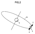
- the artificial satellite 2 orbits around the Earth E along a geostationary satellite orbit Or.
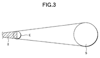
- the Earth E When the Earth E is located in the vicinity of the vernal equinox or autumnal equinox in its orbit around the sun, the Earth E casts a shadow on the artificial satellite 2 for only a predetermined period of time.
- the solar battery 4 enters an eclipse in which the solar batteries 4 cannot receive sunlight S (hereinafter, a period during which the solar batteries 4 are not exposed to sunlight will be called a "shadow period,” and a period during which the solar batteries 4 are exposed to sunlight will be called a "sunshine period").
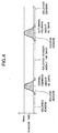
- FIG. 4 is a graph showing variations in the shadow period (described as a "shadow time” in FIG. 4) in which the artificial satellite 2 enters within a year of the Earth E.
- a shadow period arises.
- the duration of the shadow period is several minutes.
- the duration of the shadow period becomes longer and is a maximum value of about 70 minutes at the vernal and autumnal equinoxes.
- the duration of the shadow period becomes shorter in a pattern symmetric with that of the pre-equinox increase.
- a duration in which the artificial satellite 2 is in the shadow period at the time of vernal or autumnal equinox is called an eclipse season.
- the artificial satellite 2 is in the eclipse season, each day the satellite 2 is in the shadow period for several minutes to tens of minutes and in the solstice season for the remaining twenty and some hours. If the earth E is situated at a position other than the eclipse on the orbit of revolution, the artificial satellite 2 is always situated in the sunshine period (with the exception of a special situation in which the moon casts a shadow on the satellite 2). It is called a solstice season.
- FIG. 5 schematically shows the electrical configuration of the artificial satellite 2 and dose not necessarily represent the electrical configuration correctly.
- the artificial satellite 2 is equipped with an electrical drive member A which is to be electrically driven, such as a fuel injection module 7 for changing an orbit and a computer 8 (although the computer 8 is also classified as the electrical drive member A, the computer 8 is omitted from the electrical diagram for the sake of convenience).
- the electrical drive member A is connected to the solar batteries A by way of a group of switches B. During a solstice season, electricity is supplied to the electric drive member A from the solar batteries A.
- the lithium battery module 1 has the lithium battery 5; a temperature sensor 9 for measuring the temperature of the lithium battery 5; a charged state measurement sensor 10 for measuring the charged state of the lithium battery 5; the computer 8, which is connected to the temperature sensor 9 and the charged state measurement sensor 10 so as to receive signals output therefrom; a temperature controller 11 for controlling the temperature of the lithium battery 5; a charging switch 12 for charging the lithium, battery 5; and a discharging switch 13 for connecting the lithium battery 5 to the electrical drive member A.
- the lithium battery 5 is connected to the electrical drive member A by way of the discharging switch 13.
- the discharging switch 13 When the artificial satellite 2 is in a sunshine period, the discharging switch 13 is usually in a disconnected state.
- the temperature controller 11 has a heater 11A (corresponding to a "heating device") for heating the lithium battery 5, and a radiator 11B for dissipating heat from the lithium battery 5.
- the charged state measurement sensor 10 is arranged so as to measure the charged state of the lithium battery 5 on the basis of the voltage thereof.
- the temperature of the lithium battery 5 is controlled so as to fall within the range from -30°C to 10°C during the solstice season and fall within the range from 10°C to 35°C during the eclipse season.
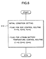
- the computer 8 sets flags to their initial conditions (S10).
- the computer 8 sets flags F1, F2, and F3 (which will be described in more detail by reference to the charged state control flowchart) controlling the charged state of the lithium battery 5 (hereinafter often referred to as "SOC"), and flags C1, C2, and C3 for controlling the temperature of the lithium battery 5, to initial values (all of which are zero) .
- the flag C1 designates the state of the artificial satellite 2.
- the flag C1 is a value of 0, the satellite 2 is in a solstice season. In contrast, when the flag C1 is a value of 1, the satellite 2 is in an eclipse season.
- the flag C2 designates the state of the heater 11A. When the flag C2 is a value of 0, the heater is in an inoperative state. In contrast, when the flag C2 is a value of 1, the heater is in an operating state.
- the flag C3 designates the state of the radiator 11B. When the flag C3 is a value of 0, the radiator 11B is in an inoperative state. In contrast, when the flag C3 is a value of 1, the radiator 11B is in an operating state.
- a temperature control processing routine shown in FIG. 7 will now be described.
- the routine is invoked from a main routine (not shown) to be performed by the computer 8, at given time intervals.
- the flag C1 is checked as to whether the satellite 2 is in the solstice season or the eclipse season (S20).
- the satellite 2 is determined to be in the solstice season.
- the solar batteries 4 are not performing generation operations, the satellite 2 is determined to be in the eclipse season.
- step 20 when flag C1 is a value of 1 (during the eclipse season), a determination is made as to whether or not the solstice season has started (S30). If NO is selected, temperature control operations for the eclipse season pertaining to step 70 and subsequent steps are performed. The following procedures are also performed even when flag C1 is a value of 0 in step 20, when in step 50 the eclipse season is determined to have started, and when in step 60 flag C1 is changed to a value of 1 (i.e., the satellite 2 is in a period of transition from the solstice season to the eclipse season).
- step 70 a determination is made as to whether or not the temperature "t" of the lithium battery 5 outputs from the temperature sensor 9 is lower than 10°C. If the temperature "t" is lower than 10°C, in step 80 the state of flag C3 is checked. In a case where flag C3 is a value of 1, the operation of the radiator 11B is terminated (S90). After flag C3 has been switched to a value of 0 (S100), processing proceeds to step 110. In a case where in step 80 flag C3 is a value of 0, processing proceeds to step 110, where the heater 11A is brought into an operating state. After flag C2 has been switched to a value of 1 (S120), processing returns to the main routine. In a case where the temperature "t" is lower than 10°C, the radiator 11B is brought into an inoperative state, and the heater 11A is brought into an operating state.
- step 70 in a case where the temperature "t" is higher than 10°C, in step 130 a determination is made as to whether or not the temperature "t” is higher than 35°C. In a case where the temperature "t” is lower than 35°C, processing returns to the main routine. In contrast, in a case where the temperature "t" is higher than 35°C, in step 140 a determination is made as to whether or not flag C2 is a value of 1. If flag C2 is a value of 1, the heater 11A is brought into an inoperative state (S150). After flag C2 has been switched to a value of 0 (S160), processing proceeds to step 170. If in step 140 flag C2 is determined to be a value of 0, the operation of the radiator 11 is started (S170).
- the temperature "t" of the lithium battery 5 is controlled so as to fall within the range of 10°C to 35°C.
- step 20 in a case where flag C1 is a value of 0 (during the solstice season), in step 50 temperature control operations for the solstice season pertaining to step 190 and subsequent steps are performed, given that the eclipse season has not yet started. The following processing operations are also performed even when in step 30 the solstice season is determined to have started and when in step 40 flag C1 is switched to a value of 0 (i.e., during a period of transition from the eclipse season to the solstice season).
- step 190 a determination is made as to whether or not the temperature "t" of the lithium battery 5 outputs from the temperature sensor 9 is lower than -30°C.
- step 80 the state of flag C3 is checked. In a case where flag C3 is a value of 1, the operation of the radiator 11B is stopped (S90). After flag C3 has been switched to a value of 1 (S100), processing proceeds to step 110. In a case where flag C3 is a value of 0 in step 80, processing proceeds to step 110, where the heater 11A is brought into an operating state. After flag C2 has been switched to a value of 1 (S120), processing returns to the main routine. In a case where the temperature "t" is lower than -30°C, the radiator 11B is brought into an inoperative state, and the heater 11A is brought into an operative state.
- step 200 a determination is made as to whether or not the temperature "t” is higher than 10°C. In a case where the temperature "t” is lower than 10°C, processing returns to the main routine. In a case where the temperature "t" is higher than 10°C, in step 140 a determination is made as to whether or not flag C2 is a value of 1. In a case where flag C2 is a value of 1, the operation of the heater 11A is stopped (S150). After flag C2 has been switched to a value of 0 (S160), processing proceeds to step 170.
- step 140 In a case where in step 140 flag C2 is a value of 0, the operation of the radiator 11B is started (S170). After flag C3 has been switched to a value of 1 (S180), processing returns to the main routine. In a case where the temperature "t" is higher than 10°C, the heater 11A is brought into an inoperative state, and the radiator 11B is brought into an operative state.
- the temperature "t" of the lithium battery 5 is controlled so as to fall within the range of -30°C to 10°C.
- FIG. 8 shows transition of the charged state of the lithium battery 5 in a case where the satellite is positioned other than the eclipse while the Earth E is on its orbit around the sun. In this position, only the solstice season is in principle continued.
- the lithium battery 5 is controlled so as to charge to a charged state of 50% or more. At this time, the lithium battery 5 is not in a floating state of charging or a trickle charging state, as is likely to be the case of a conventional secondary battery.
- the charged state drops to 50%, the lithium battery 5 is intermittently charged to 100%.
- FIG. 9 shows transition in the charged state of the lithium battery 5 when the Earth E is in an eclipse.
- the lithium battery 5 is intermittently charged so as to maintain 50% to 100%, as in the case where the satellite 2 is the solstice season (this period will be hereinafter referred to as an "intermittently charging/discharging period").
- the shadow period is started, the lithium battery 5 starts a discharge operation, thus supplying power to the satellite 2 (this period will be hereinafter referred to as a "discharging period”).
- the solstice season has started, the lithium battery 5 has been charged to 50% or more, and again enters an intermittently-charging state.
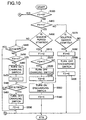
- FIGS. 6, 10, and 11 there will be described a flowchart for controlling the charged state of the lithium battery 5.
- the computer 8 sets flags to their initial conditions (S10).
- flags F1, F2, and F3 initial values of which assume “0" for controlling the charged state of the lithium battery 5 (hereinafter often called "SOC").
- Flag F1 designates the state of the lithium battery 5.
- Flag F1 is any one of values "0,” “1,” and “2.” When flag F1 is a value of "0,” the lithium battery 5 is in an intermittently charging/discharging period. When flag F1 is a value of "1,” the lithium battery 5 is in a charging period. When flag F1 is a value of "2,” the lithium battery 5 is in a discharging period.
- Flag F2 designates the state of the charging switch 12. When flag F2 is a value of 0, the charging switch 12 is in a charging/discharging-terminated state. When flag F2 is a value of 1, the charging switch 12 is in a charging/discharging state.
- Flag F3 shows the state of the discharging switch 13. When flag F3 is a value of 0, the discharging switch 13 is in a disconnected state. When flag F3 is a value of 1, the discharging switch 13 is in a discharged state.
- the routine is invoked from the main routine (not shown) to be performed by the computer 8, at predetermined time intervals.
- step S310 a determination is made as to whether or not in a solstice season has been reached.
- the solstice season is determined in accordance with a pre-programmed flow chart (not shown).
- a charging start signal may be transmitted from ground control.
- step 320 a determination is made as to whether or not flag F2 is a value of 1. In a case where flag F2 is a value of 1 (i.e., the lithium battery 5 is being charged), processing proceeds to step 360. In contrast, when flag F2 is a value of 0 (i.e., the lithium battery 5 is not being charged), in step 330 a determination is made as to whether or not SOC is a value of 30% or less. If SOC is determined to be a value of 30% or less, the charging switch 12 is brought into a connected state (S340). After flag F2 has been switched to a value of "1" (S350), processing proceeds to step 360. In a case where in step 330 SOC is determined to be a value of greater than 30%, in step 360 a determination is made as to whether or not SOC is a value of 50% or more.
- step 360 If in step 360 SOC is determined to be lower than 50%, processing returns to the main routine. In contrast, in a case where SOC is determined to be greater than 50%, the charging switch 12 is brought into a cut-off state (S370). After flag f2 has been switched to a value of 0 (S380), processing returns to the main routine.
- the lithium battery 5 is controlled such that SOC is a value of 30% to 50%, by means of an intermittent charging operation.
- step 440 a determination is made as to whether or not SOC is a value of 90% or more.
- SOC is determined to be a value of lower than 90%
- step 450 a determination is made as to whether or not flag F2 is a value of 1 (a charged state). If YES is selected, processing proceeds to step 480.
- flag F2 is a value of 0, the charging switch 12 is brought into a connected state (S460). After flag F2 has been switched to a value of 1 (S470), processing proceeds to step 480.
- step 480 a determination is made as to whether or not SOC is 100% or more. If NO is selected, processing returns to the main routine while the lithium battery 5 is held in a charging/discharging state. In contrast, if SOC has attained 100%, the charging switch 12 is brought into a cut-off state (S490). After flag F2 has been switched to a value of 0 (S500), processing returns to the main routine.
- the lithium battery 5 is charged such that SOC is a value of 90% to 100%.
- step 430 the discharging period (i.e., the shadow period) is determined to have started.
- flag F1 is switched to a value of 2 (S510), and the state of flag F2 is determined (S520).
- flag F2 is a value of 0
- processing proceeds to step 550.
- flag F2 is a value of 1 (i.e., the lithium battery 5 is being charged)
- the charging switch 12 is disconnected (S530).
- S540 After flag F2 has been switched to a value of 0 (S540), processing proceeds to step 550.
- step 550 the discharging switch 13 is brought into a connected state. After flag F3 has been switched to a value of 1 (S560), processing returns to the main routine.
- the discharging period is maintained until the solstice season (i.e., the intermittently charging/discharging period) is started.
- flag F1 is switched to a value of 0 (S580), and the discharging switch 13 is disconnected (S590).
- flag F3 has been switched to a value of 0 (S600)
- processing returns to the main routine.
- discharging of the lithium battery 5 is continued until the solstice season starts.
- the temperature “t" of the lithium battery 5 is controlled so as to be maintained in the range of 10°C to 35°C during the eclipse season.
- the temperature "t” is controlled so as to be maintained in the range of -30°C to 10°C during the solstice season.
- the SOC of the lithium battery 5 is a value of 90% to 100%.
- the SOC of the lithium battery 5 is maintained so as to be a value of 30% to 50%. For this reason, the time during which the lithium battery 5 is maintained at a fully charged state can be shortened, thus ensuring long life of the lithium battery 5.
- the expression “100% charged state” signifies the charged state of the lithium battery 5 when the lithium battery 5 is subjected to constant-voltage/constant -current charging operations for eight hours using, for example, a charging current of 0.2 CA and a maximum allowable charging voltage of the lithium battery 5.
- the expression “0% charged state” signifies the state of the lithium battery 5 when the amount of electric current corresponding to a nominal capacity of the lithium battery 5 has been discharged completely or discharged to a minimum allowable voltage.
Landscapes
- Engineering & Computer Science (AREA)
- Manufacturing & Machinery (AREA)
- Chemical & Material Sciences (AREA)
- Chemical Kinetics & Catalysis (AREA)
- Electrochemistry (AREA)
- General Chemical & Material Sciences (AREA)
- Remote Sensing (AREA)
- Aviation & Aerospace Engineering (AREA)
- Automation & Control Theory (AREA)
- Charge And Discharge Circuits For Batteries Or The Like (AREA)
- Secondary Cells (AREA)
- Hybrid Cells (AREA)
Abstract
Description
Claims (8)
- A non-aqueous electrolyte battery module for an artificial satellite comprising:a non-aqueous electrolyte battery to be provided in an artificial satellite;temperature measuring means for measuring a temperature of said non-aqueous electrolyte battery;heating/cooling means for heating or cooling said non-aqueous electrolyte battery; andbattery temperature control means for controlling said heating/cooling means on the basis of the temperature measured by said temperature measuring means;
wherein when the satellite is in a solstice season, a managed temperature of said non-aqueous electrolyte battery is equal to or lower than a managed temperature of the non-aqueous electrolyte battery achieved when the satellite is in an eclipse season. - The non-aqueous electrolyte battery module for an artificial satellite as defined in claim 1;
wherein the managed temperature of said non-aqueous electrolyte battery is set to 10°C to 35°C when the satellite is in a eclipse season, and the managed temperature of the non-aqueous electrolyte battery is set to -30°C to 10°C when the satellite is in a solstice season. - The non-aqueous electrolyte battery for an artificial satellite as defined in claim 1, further comprising:charge/discharge condition detecting means for detecting a charge/discharged state of said non-aqueous electrolyte battery;charging/discharging means for charging/discharging said non-aqueous electrolyte battery; andcharging/discharging control means for controlling said charging/discharging means on the basis of the charged state of said non-aqueous electrolyte battery detected by said charge/discharge condition detecting means;
wherein when the satellite is located in the eclipse season, the managed charged state of said non-aqueous electrolyte battery is controlled so as to be a value of 50% or more, and when the satellite is located in the solstice season, the managed charged state of said non-aqueous electrolyte battery is controlled so as to be a value of 75% or less. - The non-aqueous electrolyte battery for an artificial satellite as defined in claim 3;
wherein when the satellite is in a solstice season, the managed charged state of said non-aqueous electrolyte battery is controlled so as to be a value of 75% or less by means of intermittent charging/discharging operations. - The non-aqueous electrolyte battery for an artificial satellite as defined in claim 3;
wherein the charged state of said non-aqueous electrolyte battery is set to a value of 75% to 100% at the time of initiation of the eclipse season. - The non-aqueous electrolyte battery for an artificial satellite as defined in claim 5;
wherein the charged state of said non-aqueous electrolyte battery is set to a value of 90% to 100% at the time of initiation of the eclipse season. - The non-aqueous electrolyte battery for an artificial satellite as defined in claim 3;
wherein the charged state of said non-aqueous electrolyte battery is a value of 10% to 60% in the solstice season. - The non-aqueous electrolyte battery for an artificial satellite as defined in claim 7;
wherein the charged state of said non-aqueous electrolyte battery is a value of 30% to 50% in the solstice season.
Applications Claiming Priority (2)
| Application Number | Priority Date | Filing Date | Title |
|---|---|---|---|
| JP26441399 | 1999-09-17 | ||
| JP26441399 | 1999-09-17 |
Publications (3)
| Publication Number | Publication Date |
|---|---|
| EP1091439A2 true EP1091439A2 (en) | 2001-04-11 |
| EP1091439A3 EP1091439A3 (en) | 2002-03-06 |
| EP1091439B1 EP1091439B1 (en) | 2004-08-25 |
Family
ID=17402833
Family Applications (1)
| Application Number | Title | Priority Date | Filing Date |
|---|---|---|---|
| EP20000120027 Expired - Lifetime EP1091439B1 (en) | 1999-09-17 | 2000-09-14 | Non-aqueous electrolytic battery module for artificial satellite |
Country Status (4)
| Country | Link |
|---|---|
| US (1) | US6246217B1 (en) |
| EP (1) | EP1091439B1 (en) |
| CN (1) | CN1150650C (en) |
| DE (1) | DE60013222T2 (en) |
Cited By (3)
| Publication number | Priority date | Publication date | Assignee | Title |
|---|---|---|---|---|
| FR2903822A1 (en) * | 2006-07-17 | 2008-01-18 | Somfy Sas | Coolant installation operating method for e.g. automobile, involves utilizing energy provided by photovoltaic panel for heating battery of coolant installation, where photovoltaic panel is connected to battery by regulator |
| US9496722B2 (en) | 2009-08-05 | 2016-11-15 | Gs Yuasa International Ltd. | Battery system including bypass electrical path and heater bypass electrical path that connects a portion of bypass electrical path upstream relative to a heater to a portion of bypass electrical path downstream relative to the heater |
| CN108681347A (en) * | 2018-04-20 | 2018-10-19 | 航天东方红卫星有限公司 | A kind of temperature control system and method for optimization satellite energy use efficiency |
Families Citing this family (9)
| Publication number | Priority date | Publication date | Assignee | Title |
|---|---|---|---|---|
| US6388427B1 (en) * | 2001-09-10 | 2002-05-14 | Space Systems/Loral, Inc. | Battery temperature derivative charging |
| US6803545B2 (en) * | 2002-06-05 | 2004-10-12 | Philip Morris Incorporated | Electrically heated smoking system and methods for supplying electrical power from a lithium ion power source |
| JP5010250B2 (en) * | 2005-11-28 | 2012-08-29 | Necエナジーデバイス株式会社 | Battery stack and battery pack |
| US9368983B2 (en) * | 2011-12-15 | 2016-06-14 | The Boeing Company | Autonomous lithium-ion battery protection |
| CN102826236B (en) * | 2012-09-13 | 2015-03-25 | 上海微小卫星工程中心 | Satellite |
| US10239477B1 (en) * | 2015-12-17 | 2019-03-26 | Space Systems/Loral, Llc | Battery charge management for geosynchronous spacecraft |
| FR3046706B1 (en) * | 2016-01-07 | 2018-02-16 | Commissariat A L'energie Atomique Et Aux Energies Alternatives | METHOD AND DEVICE FOR CHARGING A BATTERY |
| RU2698638C1 (en) * | 2018-10-15 | 2019-08-28 | Акционерное общество "Научно-исследовательский институт электромеханики" (АО "НИИЭМ") | Method of operating a lithium-ion accumulator battery in a unpressurized spacecraft with radiation cooling |
| CN113734471B (en) * | 2021-08-19 | 2023-07-21 | 上海卫星工程研究所 | Autonomous coping method and system for energy shortage in shadow period of high orbit satellite |
Family Cites Families (6)
| Publication number | Priority date | Publication date | Assignee | Title |
|---|---|---|---|---|
| JP2921475B2 (en) * | 1996-03-22 | 1999-07-19 | 日本電気株式会社 | Satellite-mounted battery temperature control circuit |
| US5993993A (en) * | 1997-10-22 | 1999-11-30 | Space Systems/Loral, Inc. | Unregulated spacecraft electrical bus |
| US5957408A (en) * | 1997-12-05 | 1999-09-28 | Space Systems/Loral, Inc. | Satellite with east and west battery radiators |
| US6027076A (en) * | 1998-07-09 | 2000-02-22 | Hughes Electronics Corporation | Method for powering a spacecraft with extended-life battery operation |
| US5939864A (en) * | 1998-10-28 | 1999-08-17 | Space Systems/Loral, Inc. | Lithium-ion battery charge control method |
| US6410185B1 (en) * | 1999-02-15 | 2002-06-25 | Sony Corporation | Battery device for loading on moving body |
-
2000
- 2000-09-14 EP EP20000120027 patent/EP1091439B1/en not_active Expired - Lifetime
- 2000-09-14 DE DE2000613222 patent/DE60013222T2/en not_active Expired - Lifetime
- 2000-09-18 CN CNB001245260A patent/CN1150650C/en not_active Expired - Fee Related
- 2000-09-18 US US09/664,067 patent/US6246217B1/en not_active Expired - Lifetime
Cited By (3)
| Publication number | Priority date | Publication date | Assignee | Title |
|---|---|---|---|---|
| FR2903822A1 (en) * | 2006-07-17 | 2008-01-18 | Somfy Sas | Coolant installation operating method for e.g. automobile, involves utilizing energy provided by photovoltaic panel for heating battery of coolant installation, where photovoltaic panel is connected to battery by regulator |
| US9496722B2 (en) | 2009-08-05 | 2016-11-15 | Gs Yuasa International Ltd. | Battery system including bypass electrical path and heater bypass electrical path that connects a portion of bypass electrical path upstream relative to a heater to a portion of bypass electrical path downstream relative to the heater |
| CN108681347A (en) * | 2018-04-20 | 2018-10-19 | 航天东方红卫星有限公司 | A kind of temperature control system and method for optimization satellite energy use efficiency |
Also Published As
| Publication number | Publication date |
|---|---|
| DE60013222T2 (en) | 2005-01-13 |
| CN1150650C (en) | 2004-05-19 |
| DE60013222D1 (en) | 2004-09-30 |
| EP1091439A3 (en) | 2002-03-06 |
| US6246217B1 (en) | 2001-06-12 |
| EP1091439B1 (en) | 2004-08-25 |
| CN1289155A (en) | 2001-03-28 |
Similar Documents
| Publication | Publication Date | Title |
|---|---|---|
| US5939864A (en) | Lithium-ion battery charge control method | |
| EP1058367B1 (en) | Battery accumulating apparatus | |
| EP1091439B1 (en) | Non-aqueous electrolytic battery module for artificial satellite | |
| EP3531497B1 (en) | Battery pack temperature control method and device | |
| US8283878B2 (en) | Battery storage device system, and motor driving body and moving body using the system | |
| US20240222992A1 (en) | Method and device for controlling the level of charge of a traction battery of an electric vehicle | |
| US8022661B1 (en) | Battery over-discharge protection with dead-bus recovery | |
| US8237413B2 (en) | Method for battery charging management | |
| KR20190060497A (en) | Battery and Method for controlling battery temperature | |
| US6027076A (en) | Method for powering a spacecraft with extended-life battery operation | |
| US20050137823A1 (en) | Battery overtemperature control system and method | |
| US20130221906A1 (en) | Lithium Polymer Battery Charger and Methods Therefor | |
| JP4543208B2 (en) | Non-aqueous electrolyte battery device for artificial satellite | |
| RU2483400C2 (en) | Method to operate nickel-hydrogen accumulator batteries of spacecraft power supply system (versions) | |
| Sone et al. | Long Term Operability of Li-ion Battery under Micro-gravity Condition Demonstrated by the Satellite “REIMEI” | |
| RU2543487C2 (en) | Operating method for nickel-hydrogen batteries in power supply system of spacecraft | |
| RU2621694C2 (en) | Method for operating nickel-hydrogen accumulator batteries of aircraft electric power system | |
| RU2586172C2 (en) | Method of controlling parameters of nickel-hydrogen accumulator batteries in power supply system of spacecraft (versions) | |
| RU2313160C1 (en) | Method for making nickel-hydrogen storage battery ready for full-time service in power supply system of artificial earth satellite | |
| KR102902315B1 (en) | Charging device using heterogeneous battery | |
| CN117293950A (en) | A fully autonomous energy management and FDIR strategy design method for high-orbit spacecraft | |
| Alaoui et al. | Experiments in fast charging lead acid electric vehicle batteries | |
| RU2401485C1 (en) | Preparation of nickel-hydrogen storage battery for standard operation on artificial earth satellite | |
| US20260031649A1 (en) | Back-up power source system for cold environments | |
| RU2401486C1 (en) | Method of leveling capacity of nickel-hydrogen storage battery |
Legal Events
| Date | Code | Title | Description |
|---|---|---|---|
| PUAI | Public reference made under article 153(3) epc to a published international application that has entered the european phase |
Free format text: ORIGINAL CODE: 0009012 |
|
| AK | Designated contracting states |
Kind code of ref document: A2 Designated state(s): AT BE CH CY DE DK ES FI FR GB GR IE IT LI LU MC NL PT SE Kind code of ref document: A2 Designated state(s): DE FR |
|
| AX | Request for extension of the european patent |
Free format text: AL;LT;LV;MK;RO;SI |
|
| PUAL | Search report despatched |
Free format text: ORIGINAL CODE: 0009013 |
|
| AK | Designated contracting states |
Kind code of ref document: A3 Designated state(s): AT BE CH CY DE DK ES FI FR GB GR IE IT LI LU MC NL PT SE |
|
| AX | Request for extension of the european patent |
Free format text: AL;LT;LV;MK;RO;SI |
|
| 17P | Request for examination filed |
Effective date: 20020508 |
|
| 17Q | First examination report despatched |
Effective date: 20020710 |
|
| AKX | Designation fees paid |
Free format text: DE FR |
|
| GRAH | Despatch of communication of intention to grant a patent |
Free format text: ORIGINAL CODE: EPIDOS IGRA |
|
| GRAH | Despatch of communication of intention to grant a patent |
Free format text: ORIGINAL CODE: EPIDOS IGRA |
|
| GRAA | (expected) grant |
Free format text: ORIGINAL CODE: 0009210 |
|
| AK | Designated contracting states |
Kind code of ref document: B1 Designated state(s): DE FR |
|
| REG | Reference to a national code |
Ref country code: IE Ref legal event code: FG4D |
|
| REF | Corresponds to: |
Ref document number: 60013222 Country of ref document: DE Date of ref document: 20040930 Kind code of ref document: P |
|
| REG | Reference to a national code |
Ref country code: IE Ref legal event code: MM4A |
|
| PLBE | No opposition filed within time limit |
Free format text: ORIGINAL CODE: 0009261 |
|
| STAA | Information on the status of an ep patent application or granted ep patent |
Free format text: STATUS: NO OPPOSITION FILED WITHIN TIME LIMIT |
|
| ET | Fr: translation filed | ||
| 26N | No opposition filed |
Effective date: 20050526 |
|
| REG | Reference to a national code |
Ref country code: FR Ref legal event code: TP |
|
| REG | Reference to a national code |
Ref country code: FR Ref legal event code: TP |
|
| REG | Reference to a national code |
Ref country code: FR Ref legal event code: TP |
|
| REG | Reference to a national code |
Ref country code: DE Ref legal event code: R081 Ref document number: 60013222 Country of ref document: DE Owner name: GS YUASA INTERNATIONAL LTD., JP Free format text: FORMER OWNER: GS YUASA CORP., KYOTO, JP Effective date: 20110315 |
|
| REG | Reference to a national code |
Ref country code: FR Ref legal event code: PLFP Year of fee payment: 17 |
|
| PGFP | Annual fee paid to national office [announced via postgrant information from national office to epo] |
Ref country code: DE Payment date: 20160907 Year of fee payment: 17 |
|
| PGFP | Annual fee paid to national office [announced via postgrant information from national office to epo] |
Ref country code: FR Payment date: 20160816 Year of fee payment: 17 |
|
| REG | Reference to a national code |
Ref country code: DE Ref legal event code: R119 Ref document number: 60013222 Country of ref document: DE |
|
| REG | Reference to a national code |
Ref country code: FR Ref legal event code: ST Effective date: 20180531 |
|
| PG25 | Lapsed in a contracting state [announced via postgrant information from national office to epo] |
Ref country code: DE Free format text: LAPSE BECAUSE OF NON-PAYMENT OF DUE FEES Effective date: 20180404 |
|
| PG25 | Lapsed in a contracting state [announced via postgrant information from national office to epo] |
Ref country code: FR Free format text: LAPSE BECAUSE OF NON-PAYMENT OF DUE FEES Effective date: 20171002 |