EP1091426A2 - Structure for connecting a plurality of battery modules to constitute a battery pack - Google Patents
Structure for connecting a plurality of battery modules to constitute a battery pack Download PDFInfo
- Publication number
- EP1091426A2 EP1091426A2 EP00308834A EP00308834A EP1091426A2 EP 1091426 A2 EP1091426 A2 EP 1091426A2 EP 00308834 A EP00308834 A EP 00308834A EP 00308834 A EP00308834 A EP 00308834A EP 1091426 A2 EP1091426 A2 EP 1091426A2
- Authority
- EP
- European Patent Office
- Prior art keywords
- battery
- battery case
- projections
- adjacent
- battery modules
- Prior art date
- Legal status (The legal status is an assumption and is not a legal conclusion. Google has not performed a legal analysis and makes no representation as to the accuracy of the status listed.)
- Granted
Links
Images


Classifications
-
- H—ELECTRICITY
- H01—ELECTRIC ELEMENTS
- H01M—PROCESSES OR MEANS, e.g. BATTERIES, FOR THE DIRECT CONVERSION OF CHEMICAL ENERGY INTO ELECTRICAL ENERGY
- H01M4/00—Electrodes
- H01M4/02—Electrodes composed of, or comprising, active material
- H01M4/64—Carriers or collectors
- H01M4/66—Selection of materials
- H01M4/661—Metal or alloys, e.g. alloy coatings
-
- H—ELECTRICITY
- H01—ELECTRIC ELEMENTS
- H01M—PROCESSES OR MEANS, e.g. BATTERIES, FOR THE DIRECT CONVERSION OF CHEMICAL ENERGY INTO ELECTRICAL ENERGY
- H01M4/00—Electrodes
- H01M4/02—Electrodes composed of, or comprising, active material
- H01M4/36—Selection of substances as active materials, active masses, active liquids
- H01M4/60—Selection of substances as active materials, active masses, active liquids of organic compounds
-
- H—ELECTRICITY
- H01—ELECTRIC ELEMENTS
- H01M—PROCESSES OR MEANS, e.g. BATTERIES, FOR THE DIRECT CONVERSION OF CHEMICAL ENERGY INTO ELECTRICAL ENERGY
- H01M4/00—Electrodes
- H01M4/02—Electrodes composed of, or comprising, active material
- H01M4/62—Selection of inactive substances as ingredients for active masses, e.g. binders, fillers
- H01M4/624—Electric conductive fillers
-
- H—ELECTRICITY
- H01—ELECTRIC ELEMENTS
- H01M—PROCESSES OR MEANS, e.g. BATTERIES, FOR THE DIRECT CONVERSION OF CHEMICAL ENERGY INTO ELECTRICAL ENERGY
- H01M4/00—Electrodes
- H01M4/02—Electrodes composed of, or comprising, active material
- H01M4/62—Selection of inactive substances as ingredients for active masses, e.g. binders, fillers
- H01M4/624—Electric conductive fillers
- H01M4/625—Carbon or graphite
-
- Y—GENERAL TAGGING OF NEW TECHNOLOGICAL DEVELOPMENTS; GENERAL TAGGING OF CROSS-SECTIONAL TECHNOLOGIES SPANNING OVER SEVERAL SECTIONS OF THE IPC; TECHNICAL SUBJECTS COVERED BY FORMER USPC CROSS-REFERENCE ART COLLECTIONS [XRACs] AND DIGESTS
- Y02—TECHNOLOGIES OR APPLICATIONS FOR MITIGATION OR ADAPTATION AGAINST CLIMATE CHANGE
- Y02E—REDUCTION OF GREENHOUSE GAS [GHG] EMISSIONS, RELATED TO ENERGY GENERATION, TRANSMISSION OR DISTRIBUTION
- Y02E60/00—Enabling technologies; Technologies with a potential or indirect contribution to GHG emissions mitigation
- Y02E60/10—Energy storage using batteries
-
- Y—GENERAL TAGGING OF NEW TECHNOLOGICAL DEVELOPMENTS; GENERAL TAGGING OF CROSS-SECTIONAL TECHNOLOGIES SPANNING OVER SEVERAL SECTIONS OF THE IPC; TECHNICAL SUBJECTS COVERED BY FORMER USPC CROSS-REFERENCE ART COLLECTIONS [XRACs] AND DIGESTS
- Y02—TECHNOLOGIES OR APPLICATIONS FOR MITIGATION OR ADAPTATION AGAINST CLIMATE CHANGE
- Y02P—CLIMATE CHANGE MITIGATION TECHNOLOGIES IN THE PRODUCTION OR PROCESSING OF GOODS
- Y02P70/00—Climate change mitigation technologies in the production process for final industrial or consumer products
- Y02P70/50—Manufacturing or production processes characterised by the final manufactured product
Definitions
- the present invention relates to a battery module, and particularly to an improved structure for connecting a plurality of such battery modules arranged adjacent each other to constitute a battery pack.
- a known battery pack is constructed with a plurality of prismatic battery modules coupled adjacent each other and connected in series. End plates are arranged on the opposite ends in the direction of arrangement of the battery modules, and the battery modules are coupled together by binding these end plates with restricting bands.
- a large number of projections are formed dispersed on both sides of each battery module so that coolant passages are formed between the plurality of battery modules when they are abutted adjacent each other.
- locating protrusions and corresponding indentations are provided on both side faces of each battery module, that couple each other when the plurality of battery modules are aligned adjacent, thereby determining relative positions of neighboring battery modules.
- One battery module 31 comprises an integral battery case 32, that is formed by mutually coupling a plurality of prismatic cell cases 33 having short lateral walls and long lateral walls such that each of the short lateral walls of these cell cases is common to two adjacent cell cases as partition walls 34.
- Each cell case 33 accommodates therein elements for electromotive force in a sealed condition.
- a positive electrode connecting terminal 35 and a negative electrode connecting terminal 36 are respectively arranged at opposite ends in the lengthwise direction of the integral battery case 32.
- ribs 37 are formed at positions corresponding to the partition walls of each two neighboring cell cases, so that, when two battery modules 31 are arrange adjacent each other, they abut each other and together form coolant passages 40 between the battery modules. Further, a large number of projections 38 are protruded in a matrix fashion between the ribs 37. Both of the ribs 37 and the projections 38 have the same height.
- locating protrusions 41 and corresponding indentations 42 for receiving the locating protrusions when two battery modules are arranged side by side, for determining relative positions of neighboring battery modules 31 in a direction orthogonal to the direction of arrangement of the battery modules, are provided at opposite ends on both side faces of the battery module 31. More specifically, at one end of the battery module, a protrusion 41 is protruded on one side while an indentation 42 is formed on the other side, and at the other end of the battery module, an indentation 42 is formed on one side while a protrusion 41 is protruded on the other side.
- each integral battery case 32 of the battery modules 31 will be subject to a great load of compression, because the battery pack is constructed with the plurality of battery modules 31 arranged adjacent each other and bound tightly together.
- each integral battery case 32 receives a load from the inside of the battery module, that is generated by rises in the internal pressure of the battery module upon expansion of electrode plate group during charging and discharging or upon generation of gas. As a result, the end plates are deformed because of an excessive load, whereupon the battery modules can no longer be tied together.
- the locating protrusions 41 and indentations 42 are arranged such as shown in Fig. 8, it is possible to connect two battery modules 31 side by side, the protrusions 41 respectively fitting into corresponding indentations 42 as shown in Fig. 9, in a state that the connecting terminals 35, 35 and 36, 36 of positive polarity and of negative polarity are aligned adjacent each other. Therefore, there is the risk that the battery modules 31 can be connected by mistake in such a wrong arrangement.
- a battery module according to the present invention comprises:
- the battery module of the present invention when a plurality of battery modules are arranged side by side and bound together with a pair of end plates arranged at their opposite ends, even when there is variation on the plus side in the width of the battery modules, it can reliably be prevented that the portions of the battery module corresponding to the partitions of the cells are subject to excessive compression load exerted on the integral battery case in addition to the load generated within the battery module. Accordingly, the end plates can be prevented from being deformed by an excessive binding load.
- a battery module according to the present invention comprises:
- a battery pack 1 is constituted such that it can conveniently be employed as the drive power source for an electric vehicle and is constituted by arranging adjacent each other a plurality (in the example illustrated, 15) of prismatic battery modules 2 of flat plate shape comprising nickel metal hydride batteries.
- Positive electrode and negative electrode connecting terminals 11, 12 project at the upper ends of both end faces in the direction of elongation of battery modules 2, the positive electrode and negative electrode connecting terminals 11, 12 of battery modules 2 being adjacently arranged so as to be alternately in opposite directions as shown in Fig. 6; thus, battery modules 2 are connected in series by sequential mutual connection of adjacent connecting terminals 11, 12.
- End plates 13, 14 are arranged at both ends in the direction of adjacent arrangement of the battery modules 2, their upper ends and lower ends being tied together by a plurality of restraining bands 15 respectively arranged with a suitable separation, whereby a battery pack 1 is constituted as an integral body.
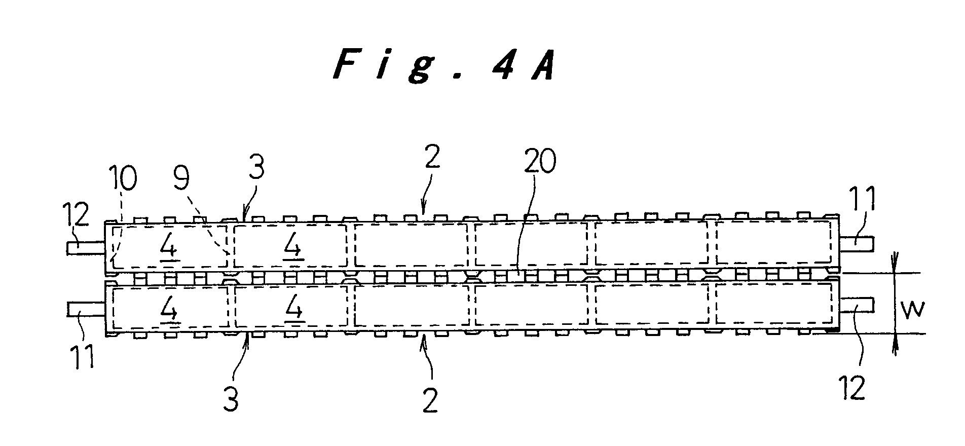
- battery modules 2 are constituted by an integral battery case 3 formed by mutually unitarily linking a plurality (in this embodiment, six) of rectangular prismatic cell cases 4 having short lateral walls and long lateral walls, the short lateral walls being shared as partitions 9 between the cell cases 4, 4, and the outside short lateral walls of the cell cases 4 at both ends constituting the end walls 10 of the integral battery case.
- Cells 5 are constituted by accommodating electrolyte and electrode groups consisting of a large number of positive electrode plates and negative electrode plates within cell cases 4 parallel with the long lateral walls and stacked in the direction of the short lateral walls with intervening separators.
- a battery module 2 is constituted by connecting these six cells 5 in series within an integral battery case 3, connecting terminals 11, 12 being connected to the cells at both ends.
- the upper end of the integral battery case 3 is closed by a lid 6 that is integrally joined thereto.
- a safety vent 7 for releasing pressure when the internal pressure of the cells reaches a predetermined value.
- temperature detection holes 8 fitted with temperature detection sensors for detecting the temperature of each cell 5 are formed therein.
- the long lateral walls of six cells 5 together form an integral side face of the integral battery case 3.
- rib-shaped projections 16 extending vertically in positions opposite partitions 9 and end walls 10 of the two side ends of cell cases 4 are provided, and a large number of comparatively small circular projections 17 or the like are provided in a matrix arrangement with a suitable pitch between rib-shaped projections 16, 16.
- the height h of the rib-shaped projections 16 opposite partitions 9 and end walls 10 of cell cases 4 is set lower than the height H of the circular projections 17.
- the rib-shaped projections 16, the circular projections 17, and the coupling ribs 18 and 19 form coolant passages 20 for cooling the cell cases 4 effectively and uniformly.
- Protrusions 21 and indentations 22, for positioning and fitting together battery modules 2 when they are abutted on each other, are arranged at an upper portion and a lower portion of the outer surface of the two rib-shaped projections 16 near both ends of the long side wall of the integral battery case 3, as shown in Fig. 3 and Fig. 5.
- the protrusions 21 and indentations 22 are positioned symmetrical with respect to the centerline in the lengthwise direction of the battery module 2 on both side faces of the integral battery case 3. At one end of the battery module 2, the protrusions 21 project from the opposite side faces of the battery module 2, while the indentations 22 are formed at the other end of the battery module 2 on the opposite side faces of the battery module 2.
- a plurality of battery modules 2 are arranged adjacent each other, a pair of end plates 13, 14 are arranged at opposite ends of these battery modules, and they are all bound together with restricting bands to be an integral body.
- the predetermined number of battery modules 2 are bound together as arranged adjacent each other and thus their dimensions are restricted to fixed values. Even when there is variation on the plus side in the width W of the integral battery case 3 of battery module 2, such can be accommodated by elastic deformation of side walls of the integral battery case 3 except for portions corresponding to the partitions 9 between each two adjacent cells in the battery module. Also in such portions of the side walls of the integral battery case 3 corresponding to the partitions 9, because the height h of the rib-shaped projections 16 is set lower than the height H of the circular projections 17 as shown in Fig. 4B, there is a gap between the opposed rib-shaped projections 16, whereby the variation on the plus side of the integral battery case 3 can readily be accommodated.
- the portions corresponding to the partitions 9 between each two cells are hardly deformable, the compression load that the integral battery case 3 receives in addition to the load generated from the inside of each cell 5 of the battery module 2 can be prevented from being excessive at these portions. Accordingly, the end plates 13, 14 can be prevented from being deformed by an excessive binding load.
- a large number of projections are formed dispersedly on both side faces of the battery module, which form coolant passages between battery modules when they are arranged side by side by butting each other, wherein the height of the projections positioned opposite the partitions between each two cells in a battery module is set lower than the height of other projections.
- locating protrusions and indentations for receiving the protrusions are formed at both ends in the lengthwise direction of the battery module at positions symmetrical with the centerline in the lengthwise direction of the battery module, such that protrusions project from opposite side faces of the battery module, and the indentations are formed on the opposite side faces of the battery module.
Landscapes
- Chemical & Material Sciences (AREA)
- Chemical Kinetics & Catalysis (AREA)
- Electrochemistry (AREA)
- General Chemical & Material Sciences (AREA)
- Engineering & Computer Science (AREA)
- Materials Engineering (AREA)
- Secondary Cells (AREA)
- Battery Mounting, Suspending (AREA)
- Sealing Battery Cases Or Jackets (AREA)
- Connection Of Batteries Or Terminals (AREA)
Abstract
Description
Claims (4)
- A battery module comprising:a plurality of prismatic cell cases (4) having short lateral walls and long lateral walls coupled together such that each of the short lateral walls of these cell cases is common to two adjacent cell cases as partitions (9), thereby constituting an integral battery case (3), and each of the cell cases respectively accommodating therein elements for electromotive force; anda plurality of projections (16, 17) formed dispersedly on both side faces of the battery module (2) for forming coolant passages (20) between two battery modules when butted with corresponding plurality of projections formed on both sides of an adjacent battery module, whereinpart of the projections (16) positioned opposite the partitions (9) in the integral battery case (3) have a height smaller than the other projections (17).
- A battery module comprising:a prismatic battery case (3);a connecting terminal (11) of positive polarity and a connecting terminal (12) of negative polarity arranged respectively at lengthwise opposite ends of the battery case; anda plurality of protrusions (21) and a plurality of indentations (22) formed on both side faces of the battery case at positions near the lengthwise opposite ends of the battery case symmetrical with respect to a centerline in the lengthwise direction of the battery case, wherein the protrusions are in pairs formed opposite each other to protrude from opposite side faces of the battery case, and the indentations are in pairs formed opposite each other on the opposite side faces of the battery case.
- A battery pack comprising:a plurality of battery modules (2) having connecting terminals (11, 12) of positive and negative polarities respectively at lengthwise opposite ends thereof, arranged adjacent each other oppositely such that the connecting terminal of positive polarity and the connecting terminal of negative polarity of two adjacent battery modules are aligned adjacent each other;end plates (13, 14) arranged at lengthwise opposite ends of the plurality of battery modules arranged together;restricting bands (15) for coupling the battery modules and the end plates together, whereina battery module comprisesa plurality of prismatic cell cases (4) having short lateral walls and long lateral walls coupled together such that each of the short lateral walls of these cell cases is common to two adjacent cell cases as partitions (9), thereby constituting an integral battery case (3), and each of the cell cases respectively accommodating therein elements for electromotive force; anda plurality of projections (16, 17) formed dispersedly on both side faces of the battery module for forming coolant passages (20) between two battery modules (2) when butted with corresponding plurality of projections formed on both sides of an adjacent battery module, whereinpart of the projections (16) positioned opposite the partitions (9) in the integral battery case (3) have a height smaller than the other projections (17).
- A battery pack comprising:a plurality of battery modules (2) having connecting terminals (11, 12) of positive and negative polarities respectively at lengthwise opposite ends thereof, arranged adjacent each other oppositely such that the connecting terminal of positive polarity and the connecting terminal of negative polarity of two adjacent battery modules are aligned adjacent each other;end plates (13, 14) arranged at lengthwise opposite ends of the plurality of battery modules arranged together;restricting bands (15) for coupling the battery modules and the end plates together, whereina battery module comprisesa plurality of protrusions (21) and a plurality of indentations (22) formed on both side faces of the battery case at positions near the lengthwise opposite ends of the battery case symmetrical with respect to a centerline in the lengthwise direction of the battery case, wherein the protrusions are in pairs formed opposite each other to protrude from opposite side faces of the battery case, and the indentations are in pairs formed opposite each other on the opposite side faces of the battery case.
Applications Claiming Priority (2)
| Application Number | Priority Date | Filing Date | Title |
|---|---|---|---|
| JP28879499A JP4310010B2 (en) | 1999-10-08 | 1999-10-08 | Unit battery |
| JP28879499 | 1999-10-08 |
Publications (3)
| Publication Number | Publication Date |
|---|---|
| EP1091426A2 true EP1091426A2 (en) | 2001-04-11 |
| EP1091426A3 EP1091426A3 (en) | 2002-04-03 |
| EP1091426B1 EP1091426B1 (en) | 2007-05-16 |
Family
ID=17734825
Family Applications (1)
| Application Number | Title | Priority Date | Filing Date |
|---|---|---|---|
| EP00308834A Expired - Lifetime EP1091426B1 (en) | 1999-10-08 | 2000-10-06 | Structure for connecting a plurality of battery modules to constitute a battery pack |
Country Status (4)
| Country | Link |
|---|---|
| US (1) | US6517966B1 (en) |
| EP (1) | EP1091426B1 (en) |
| JP (1) | JP4310010B2 (en) |
| DE (1) | DE60034855T2 (en) |
Cited By (3)
| Publication number | Priority date | Publication date | Assignee | Title |
|---|---|---|---|---|
| EP1990861A1 (en) * | 2007-05-08 | 2008-11-12 | Sanyo Electric Co., Ltd. | Battery pack |
| US8163420B2 (en) | 2008-12-27 | 2012-04-24 | Sanyo Electric Co., Ltd. | Battery system with battery cells held in a stack by metal bands |
| US9531045B2 (en) | 2011-07-14 | 2016-12-27 | Hanon Systems | Battery cooler |
Families Citing this family (34)
| Publication number | Priority date | Publication date | Assignee | Title |
|---|---|---|---|---|
| JP4626034B2 (en) * | 2000-09-08 | 2011-02-02 | パナソニック株式会社 | Collective sealed secondary battery |
| JP4127985B2 (en) * | 2001-07-23 | 2008-07-30 | 松下電器産業株式会社 | Battery pack |
| US7138205B2 (en) * | 2001-10-02 | 2006-11-21 | Matsushita Electric Industrial Co., Ltd. | Battery with proportional collectors, straps, and plates |
| JP4242665B2 (en) * | 2002-05-13 | 2009-03-25 | パナソニック株式会社 | Battery pack cooling device and secondary battery |
| JP3624903B2 (en) * | 2002-07-04 | 2005-03-02 | 日産自動車株式会社 | Module battery |
| ATE454886T1 (en) * | 2003-03-26 | 2010-01-15 | Egalet As | MATRIX PREPARATIONS FOR THE CONTROLLED PRESENTATION OF MEDICINAL MEDICINAL PRODUCTS |
| JP3730981B2 (en) * | 2003-10-01 | 2006-01-05 | Necラミリオンエナジー株式会社 | Film outer battery and battery pack |
| KR100649561B1 (en) * | 2004-09-21 | 2006-11-24 | 삼성에스디아이 주식회사 | Case, Secondary Battery and Battery Module |
| KR100669414B1 (en) * | 2004-11-30 | 2007-01-15 | 삼성에스디아이 주식회사 | Battery Modules and Battery Modules |
| US7604896B2 (en) | 2005-03-16 | 2009-10-20 | Ford Global Technologies, Llc | High voltage battery assembly for a motor vehicle |
| CN101395781B (en) * | 2005-03-16 | 2011-09-14 | 福特全球技术公司 | Power supply temperature sensor and system |
| KR100684795B1 (en) * | 2005-03-29 | 2007-02-20 | 삼성에스디아이 주식회사 | Secondary Battery and Secondary Battery Module |
| KR100612239B1 (en) * | 2005-04-26 | 2006-08-11 | 삼성에스디아이 주식회사 | Secondary battery partition wall forming the secondary battery module and the secondary battery module |
| KR100684766B1 (en) * | 2005-07-29 | 2007-02-20 | 삼성에스디아이 주식회사 | Secondary battery module |
| KR100892047B1 (en) * | 2006-09-18 | 2009-04-07 | 주식회사 엘지화학 | Battery Modules and Medium and Large Battery Packs |
| JP2009110832A (en) * | 2007-10-31 | 2009-05-21 | Sanyo Electric Co Ltd | Square battery and battery pack |
| DE102009006465A1 (en) * | 2009-01-28 | 2010-07-29 | Li-Tec Battery Gmbh | battery module |
| US9023507B2 (en) * | 2009-06-01 | 2015-05-05 | Gs Yuasa International, Ltd. | Battery assembly and method of manufacturing the same |
| KR101137365B1 (en) * | 2010-05-20 | 2012-04-20 | 에스비리모티브 주식회사 | Battery pack |
| WO2012059951A1 (en) | 2010-11-01 | 2012-05-10 | トヨタ自動車株式会社 | Power storage device |
| CN103380511B (en) * | 2011-01-10 | 2016-08-10 | 科瓦西斯有限责任公司 | Adaptive battery modules for prismatic cells |
| JP6091783B2 (en) * | 2012-07-17 | 2017-03-08 | 株式会社東芝 | Battery pack |
| DE102012219301A1 (en) | 2012-10-23 | 2014-02-13 | Robert Bosch Gmbh | Module carrier for carrying e.g. lithium-ion battery module that is utilized as powerful energy storage unit in e.g. hybrid car, has base plate comprising two fluid channels, and lateral plate comprising terminal for fluid channels |
| DE102013203434A1 (en) | 2013-02-28 | 2014-08-28 | Robert Bosch Gmbh | Battery for vehicle, has rope extending around protruding attachment elements that are extended between battery modules and cooling plate, where battery modules are alternately guided back and forth and stressed against cooling plate |
| KR102263061B1 (en) | 2014-09-15 | 2021-06-09 | 삼성전자주식회사 | Flexible electrode assembly and electrochemical device having the electrode assembly |
| KR102303827B1 (en) | 2014-10-06 | 2021-09-17 | 삼성전자주식회사 | Complex electrode assembly including a plurality of electrode assemblies and electrochemical device comprising the complex electrode assembly |
| JP6684613B2 (en) * | 2016-03-10 | 2020-04-22 | プライムアースEvエナジー株式会社 | Battery module and battery pack |
| EP3309858B1 (en) * | 2016-10-13 | 2019-07-10 | Samsung SDI Co., Ltd. | Battery module carrier, battery system and use of a modified h-beam as battery module carrier |
| US10978884B2 (en) | 2018-08-10 | 2021-04-13 | Powin Energy Corporation | Enhanced switched balancing network for battery pack |
| EP3850687A4 (en) * | 2018-09-11 | 2022-07-20 | Powin, LLC | MODULAR BATTERY STACK AND CARRIER SYSTEM |
| MX2021011134A (en) | 2019-03-14 | 2021-12-10 | Generac Power Systems Inc | THERMAL MANAGEMENT OF THE BATTERY MODULE. |
| US12494530B2 (en) | 2020-01-17 | 2025-12-09 | Microvast Inc. | Battery pack and electric vehicle |
| JP7348930B2 (en) * | 2021-07-06 | 2023-09-21 | プライムプラネットエナジー&ソリューションズ株式会社 | Energy storage module |
| CN117423945A (en) * | 2023-10-27 | 2024-01-19 | 宁夏宝丰昱能科技有限公司 | Battery rack, manufacturing method of battery rack and battery pack |
Family Cites Families (4)
| Publication number | Priority date | Publication date | Assignee | Title |
|---|---|---|---|---|
| US5663007A (en) * | 1994-02-23 | 1997-09-02 | Matsushita Electric Industrial Co., Ltd. | Sealed storage battery and method for manufacturing the same |
| JPH0822811A (en) * | 1994-07-05 | 1996-01-23 | Matsushita Electric Ind Co Ltd | Storage battery case and sealed alkaline storage battery |
| JP3598627B2 (en) * | 1996-01-17 | 2004-12-08 | 松下電器産業株式会社 | Battery case for storage battery and storage battery |
| JP4572019B2 (en) * | 1999-10-08 | 2010-10-27 | パナソニック株式会社 | Assembled battery |
-
1999
- 1999-10-08 JP JP28879499A patent/JP4310010B2/en not_active Expired - Fee Related
-
2000
- 2000-10-06 US US09/684,251 patent/US6517966B1/en not_active Expired - Lifetime
- 2000-10-06 EP EP00308834A patent/EP1091426B1/en not_active Expired - Lifetime
- 2000-10-06 DE DE60034855T patent/DE60034855T2/en not_active Expired - Lifetime
Cited By (3)
| Publication number | Priority date | Publication date | Assignee | Title |
|---|---|---|---|---|
| EP1990861A1 (en) * | 2007-05-08 | 2008-11-12 | Sanyo Electric Co., Ltd. | Battery pack |
| US8163420B2 (en) | 2008-12-27 | 2012-04-24 | Sanyo Electric Co., Ltd. | Battery system with battery cells held in a stack by metal bands |
| US9531045B2 (en) | 2011-07-14 | 2016-12-27 | Hanon Systems | Battery cooler |
Also Published As
| Publication number | Publication date |
|---|---|
| JP4310010B2 (en) | 2009-08-05 |
| JP2001110385A (en) | 2001-04-20 |
| EP1091426A3 (en) | 2002-04-03 |
| DE60034855D1 (en) | 2007-06-28 |
| US6517966B1 (en) | 2003-02-11 |
| EP1091426B1 (en) | 2007-05-16 |
| DE60034855T2 (en) | 2007-11-29 |
Similar Documents
| Publication | Publication Date | Title |
|---|---|---|
| EP1091426B1 (en) | Structure for connecting a plurality of battery modules to constitute a battery pack | |
| EP1091438B1 (en) | Battery pack | |
| KR100876458B1 (en) | Battery cartridge of novel structure and open battery module containing it | |
| US6821673B1 (en) | Battery module, and rechargeable battery for constituting the battery module | |
| US7611798B2 (en) | Bus bar for electric connection and middle and battery module comprising the same | |
| EP1091427B1 (en) | Structure for fixing electrode plate groups in cells that constitute a battery module | |
| CN108701793B (en) | Battery | |
| KR101305218B1 (en) | Battery Module Having Fixing Member and Coupling Member, and Battery Pack Employed with the Same | |
| KR20200044578A (en) | Large module of battery | |
| KR20200044577A (en) | Large module of battery | |
| WO2007066919A1 (en) | Assemblable spacer for preparation of battery module | |
| US7947389B2 (en) | Cartridge frame with connectors for battery pack | |
| US6340311B1 (en) | Structure for connecting a plurality of battery modules to constitute a battery pack | |
| EP1199759B1 (en) | Battery module | |
| KR100904375B1 (en) | Fuse-mounted battery cartridges and battery modules containing them | |
| KR20190051886A (en) | Battery pack module with improved durability and usability | |
| KR102911620B1 (en) | Battery Pack Assembled without Fastener | |
| JP7821310B2 (en) | Battery Block | |
| KR102796030B1 (en) | Stack type battery pack with preventing heat dissipation efficiency reduction | |
| EP4708508A1 (en) | Battery pack and vehicle including same | |
| EP4611168A1 (en) | Battery module and battery pack comprising same |
Legal Events
| Date | Code | Title | Description |
|---|---|---|---|
| PUAI | Public reference made under article 153(3) epc to a published international application that has entered the european phase |
Free format text: ORIGINAL CODE: 0009012 |
|
| AK | Designated contracting states |
Kind code of ref document: A2 Designated state(s): DE FR GB Kind code of ref document: A2 Designated state(s): AT BE CH CY DE DK ES FI FR GB GR IE IT LI LU MC NL PT SE |
|
| AX | Request for extension of the european patent |
Free format text: AL;LT;LV;MK;RO;SI |
|
| PUAL | Search report despatched |
Free format text: ORIGINAL CODE: 0009013 |
|
| AK | Designated contracting states |
Kind code of ref document: A3 Designated state(s): AT BE CH CY DE DK ES FI FR GB GR IE IT LI LU MC NL PT SE |
|
| AX | Request for extension of the european patent |
Free format text: AL;LT;LV;MK;RO;SI |
|
| 17P | Request for examination filed |
Effective date: 20020911 |
|
| AKX | Designation fees paid |
Free format text: DE FR GB |
|
| 17Q | First examination report despatched |
Effective date: 20050623 |
|
| GRAP | Despatch of communication of intention to grant a patent |
Free format text: ORIGINAL CODE: EPIDOSNIGR1 |
|
| GRAS | Grant fee paid |
Free format text: ORIGINAL CODE: EPIDOSNIGR3 |
|
| GRAA | (expected) grant |
Free format text: ORIGINAL CODE: 0009210 |
|
| AK | Designated contracting states |
Kind code of ref document: B1 Designated state(s): DE FR GB |
|
| REG | Reference to a national code |
Ref country code: GB Ref legal event code: FG4D |
|
| REF | Corresponds to: |
Ref document number: 60034855 Country of ref document: DE Date of ref document: 20070628 Kind code of ref document: P |
|
| ET | Fr: translation filed | ||
| PLBE | No opposition filed within time limit |
Free format text: ORIGINAL CODE: 0009261 |
|
| STAA | Information on the status of an ep patent application or granted ep patent |
Free format text: STATUS: NO OPPOSITION FILED WITHIN TIME LIMIT |
|
| 26N | No opposition filed |
Effective date: 20080219 |
|
| REG | Reference to a national code |
Ref country code: DE Ref legal event code: R084 Ref document number: 60034855 Country of ref document: DE |
|
| REG | Reference to a national code |
Ref country code: GB Ref legal event code: 746 Effective date: 20160809 |
|
| REG | Reference to a national code |
Ref country code: FR Ref legal event code: PLFP Year of fee payment: 17 |
|
| REG | Reference to a national code |
Ref country code: FR Ref legal event code: PLFP Year of fee payment: 18 |
|
| REG | Reference to a national code |
Ref country code: FR Ref legal event code: PLFP Year of fee payment: 19 |
|
| PGFP | Annual fee paid to national office [announced via postgrant information from national office to epo] |
Ref country code: FR Payment date: 20190913 Year of fee payment: 20 |
|
| PGFP | Annual fee paid to national office [announced via postgrant information from national office to epo] |
Ref country code: DE Payment date: 20190924 Year of fee payment: 20 |
|
| PGFP | Annual fee paid to national office [announced via postgrant information from national office to epo] |
Ref country code: GB Payment date: 20191003 Year of fee payment: 20 |
|
| REG | Reference to a national code |
Ref country code: DE Ref legal event code: R071 Ref document number: 60034855 Country of ref document: DE |
|
| REG | Reference to a national code |
Ref country code: GB Ref legal event code: PE20 Expiry date: 20201005 |
|
| PG25 | Lapsed in a contracting state [announced via postgrant information from national office to epo] |
Ref country code: GB Free format text: LAPSE BECAUSE OF EXPIRATION OF PROTECTION Effective date: 20201005 |