EP1091381A2 - Color cathode ray tube - Google Patents
Color cathode ray tube Download PDFInfo
- Publication number
- EP1091381A2 EP1091381A2 EP00121217A EP00121217A EP1091381A2 EP 1091381 A2 EP1091381 A2 EP 1091381A2 EP 00121217 A EP00121217 A EP 00121217A EP 00121217 A EP00121217 A EP 00121217A EP 1091381 A2 EP1091381 A2 EP 1091381A2
- Authority
- EP
- European Patent Office
- Prior art keywords
- portions
- tongue
- cathode ray
- main surface
- ray tube
- Prior art date
- Legal status (The legal status is an assumption and is not a legal conclusion. Google has not performed a legal analysis and makes no representation as to the accuracy of the status listed.)
- Withdrawn
Links
Images


Classifications
-
- H—ELECTRICITY
- H01—ELECTRIC ELEMENTS
- H01J—ELECTRIC DISCHARGE TUBES OR DISCHARGE LAMPS
- H01J29/00—Details of cathode-ray tubes or of electron-beam tubes of the types covered by group H01J31/00
- H01J29/02—Electrodes; Screens; Mounting, supporting, spacing or insulating thereof
- H01J29/06—Screens for shielding; Masks interposed in the electron stream
- H01J29/07—Shadow masks for colour television tubes
-
- H—ELECTRICITY
- H01—ELECTRIC ELEMENTS
- H01J—ELECTRIC DISCHARGE TUBES OR DISCHARGE LAMPS
- H01J2229/00—Details of cathode ray tubes or electron beam tubes
- H01J2229/07—Shadow masks
- H01J2229/0716—Mounting arrangements of aperture plate to frame or vessel
-
- H—ELECTRICITY
- H01—ELECTRIC ELEMENTS
- H01J—ELECTRIC DISCHARGE TUBES OR DISCHARGE LAMPS
- H01J2229/00—Details of cathode ray tubes or electron beam tubes
- H01J2229/07—Shadow masks
- H01J2229/0727—Aperture plate
- H01J2229/0766—Details of skirt or border
- H01J2229/0772—Apertures, cut-outs, depressions, or the like
Definitions
- the present invention relates to a color cathode ray tube, and more particularly to a color cathode ray tube which is capable of preventing the deformation of a color selection electrode such as a shadow mask.
- a color cathode ray tube for example, a shadow-mask type color cathode ray tube employed by a color television set, a color display monitor for an OA apparatus terminal or the like includes an evacuated envelope which is comprised of an approximately rectangular panel portion which has a phosphor screen including a large number of dot-like or stripe-like phosphor picture elements, an approximately tubular neck portion accommodating an electron gun and an approximately funnel-like funnel portion which connects the neck portion and the panel portion.
- a shadow mask which constitutes a color selection electrode having a large number of electron beam apertures is disposed. That is, the shadow mask is disposed close to the phosphor screen, faces the phosphor screen in an opposed manner and is fixedly secured to a mask frame.
- This shadow mask mainly uses aluminum killed steel as a constituent material.
- shadow masks having a thin plate thickness have been used.
- a portion thereof is thermally deformed during its operation and a phenomenon called a mask doming which displaces electron beam spots from given positions on the phosphor screen is liable to occur.
- a shadow mask suspension mechanism has been improved and furthermore Invar material is used as the constituent material of the shadow mask in view of the thermal expansion rate and the physical hardness.
- an original plate having a large number of above-mentioned electron beam apertures at given positions by etching is blanked out to a given shape.
- the blanked plate is formed by a press into a shape which includes a main surface having an approximately spherical plane and skirt portions contiguously connected to the periphery of this main surface and are bent at approximately 90 degrees relative to the main surface.
- this shaped shadow mask is fixedly secured to the above-mentioned mask frame to constitute a mask assembly.
- a so-called spring back is generated in the skirt portions and hence, a warping is generated on the skirt portions in an outside direction, that is, in a direction to move away from a tube axis.
- Japanese Laid-open Patent Publication 112566/1974 discloses a technique which prevents deformation by locally thinning the thickness of a peripheral portion of the main surface of the shadow mask.
- Japanese Laid-open Patent Publication 271849/1988 discloses a technique which prevents deformation by setting the length of the skirt portions of the shadow mask to a specific value relative to the outer diameter dimension of the panel, by providing tongues which protrude from the skirt portions in a direction away from the main surface approximately parallel to the tube axis and by fixedly securing the tongues to the mask frame.
- Japanese Laid-open Patent Publication 169847/1989 discloses a technique which prevents deformation by forming a large number of approximately circular small holes in the skirt portions at the corner portions of the shadow mask.
- Japanese Laid-open Patent Publication 35657/1997 discloses a technique which prevents deformation by forming a plurality of stress absorption holes in the skirt portions of the shadow mask.
- a technique which prevents the deformation by thinning the area ranging from the end portion of the main surface to the skirt portions by forming non-through holes or grooves on such an area is disclosed in various publications.
- the conventional technique which thins the thickness of the area ranging from the end portion of the main surface to the skirt portions or forms through holes only in the skirt portions has a limit and hence is still insufficient in preventing the deformation. Further, with respect to the shadow mask having the large radius of curvature of the main surface, there has been a problem that the deformation prevention effect can be hardly expected.
- a typical object of the present invention to provide a color cathode ray tube which can prevent the deformation of a color selection electrode such as a shadow mask.
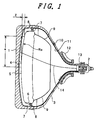
- Fig. 1 is a cross-sectional view for explaining an example of the whole structure of a shadow-mask type color cathode ray tube showing one embodiment of the present invention.
- numeral 1 indicates a panel portion
- numeral 2 indicates a neck portion
- numeral 3 indicates a funnel portion
- numeral 4 indicates a phosphor film
- numeral 5 indicates a shadow mask which constitutes a color selection electrode having a large number of electron beam apertures
- numeral 6 indicates a mask frame having a structure which will be explained later for fixing and holding the shadow mask 5 and the like.
- Numeral 7 indicates a spring
- numeral 8 indicates a panel pin
- numeral 9 indicates a magnetic shield
- numeral 10 indicates an anode button
- numeral 11 indicates an interior conductive film
- numeral 12 indicates a deflection yoke which deflects electron beams in the horizontal direction and the vertical direction
- numeral 13 indicates an electron gun for emitting three electron beams 14 (one center electron beam and two side electron beams).
- the mask frame 6 which fixedly secures the shadow mask 5 and the magnetic shield 9 and the like thereto is mounted on panel pins 8 in a suspended manner by means of springs 7.
- the panel portion 1 and the funnel portion 3 are fixedly secured to each other by welding using frit glass. Then, the electron gun 13 is inserted into the neck portion 2 and is vacuum sealed.
- the electron beams 14 emitted from the electron guns 13 receive the deflection in two directions consisting of the horizontal and vertical directions by the deflection yoke 12 which is mounted on a transitional portion between the neck portion 2 and the funnel portion 3 and impinge on the phosphor film 4 after passing through the electron beam apertures of the shadow mask 5 which constitutes the color selection electrode.
- Fig. 1 illustrates the shadow-mask type color cathode ray tube of a flat type.
- the panel portion 1 has an approximately flattened outer surface and an inner surface which is curved so as to form a recessed surface.
- the shadow mask 5 is formed by shaping the shadow mask original plate into a given curved surface by press forming and is curved following the inner surface of the panel portion 1. The reason why the inner surface of the panel portion 1 and the shadow mask 5 are curved while the outer surface of the panel portion 1 is held approximately flat is that the manufacturing method of the shadow mask 5 by the press molding technique becomes simple and inexpensive.
- An apertured region (a main surface) of the shadow mask 5 in which a large number of electron beam apertures are formed has an approximately rectangular shape and respective radii of curvature along the long axis, along the short axis and along the diagonal axis are made different from each other. This design is made so as to satisfy both of the feeling of flatness of the screen required as the color cathode ray tube and the maintenance of the mechanical strength of the shaped shadow mask.
- the curved surface of the shadow mask 5 is a non-spherical surface which gradually decreases the radii of curvature along the long axis, along the short axis and the diagonal axis respectively from the center to the periphery of the main surface 21.
- the radius of curvature Rx along the long axis is varied within a range from 1450 mm to 1250 mm
- the radius of curvature Ry along the short axis is varied within a range from 2000 mm to 1300 mm
- the radius of curvature Rd along the diagonal axis is varied within a range from 1600 mm to 1250 mm.
- the feeling of flatness is not damaged and hence, it is sufficient so long as the radius of curvature is set equal to or more than 1250 mm.
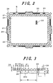
- Fig. 2 is a plan view showing one example of a shadow mask original plate before shaping used in a color cathode ray tube of the present invention.
- numeral 21 indicates a shadow mask main surface.
- the shadow mask main surface 21 is a portion which faces the phosphor film formed on the panel portion after shaping.
- the shadow mask main surface 21 is provided with a large number of electron beam apertures 22 and an outer peripheral portion 23 indicated by hatching is formed of a non-apertured portion.
- Numeral 24 indicates skirt portions and these skirt portions 24 are disposed at long and short sides disposed at the outside of the peripheral portion 23.
- the skirt portions 24 have a large number of stress absorption holes 25 formed of elliptically shaped through holes.
- Numeral 26 indicates tongue portions and these tongue portions 26 are continuously provided to the distal end portions of the skirt portions 24 at the center of respective sides.
- Each tongue portion 26 is provided with stress absorption holes 27 formed of circular through holes.
- Numeral 28 indicates corner members provided to respective corner portions and these corner members 28 are fixedly secured to respective corner portions of the mask frame 6.
- the stress absorption holes 25 are not formed in portions of the skirt portions 24 disposed at both sides of the corner members 28.
- the approximately entire surface of the shadow mask original plate is made thin by etching except for portions disposed in the vicinity of the distal end portions of the tongue portions 26 which are fixedly welded to the mask frame and the portion where the electron beam apertures are formed.
- the tongue portions 26 are formed in respective long and shorts sides in this embodiment, it may be possible to make the short sides have only the skirt portions and to make only the long sides have the tongue portions.
- Fig. 3 is a plan view of an essential part showing a portion of Fig. 2 in an enlarged form, wherein same numerals are given to parts identical to those shown in Fig. 2.
- the diameter and the pitch of the stress absorption holes 27 formed in the tongue portions 26 are indicated by D1 and P1 respectively
- the short diameter, the long diameter and the pitch of the stress absorption holes 25 formed in the skirt portions 24 are indicated by D2, D3 and P2
- the height of the tongue portions 26 is indicated by H
- the distance from distal end portions 26a of the tongue portions 26 to the stress absorption holes 27 is indicated by S1
- the distance from distal ends 26a of the tongue portions 26 to the upper ends of the stress absorption holes 25 is indicated by S2
- the width of the tongue portions 26 is indicated by W.
- respective stress absorption holes 27 are arranged approximately parallel to the peripheral direction of the outer peripheral portion 23 and further they are aligned with each other.
- respective stress absorption holes 25 are also arranged approximately parallel to the peripheral direction of the outer peripheral portion 23 and further they are aligned with each other.
- the distance S1 is set to equal to more than 3 mm, the cracks on the skirt portions which may be caused by the press shaping can be effectively prevented. Accordingly, it is desirable to set the distance S1 to equal to or more than 3 mm.
- the above-mentioned drop strength is obtained by a method which has been carried out as a general test method of a color cathode ray tube. That is, a completed bulb shown in Fig. 1 is accommodated in a test box formed like a packaging box with a panel surface thereof directed upwardly, and then a probe is mounted approximately on the center of the outer surface of the panel. Then, under this state, the completed bulb is dropped from a given height together with the test box and the drop strength is obtained from the measured value of the probe.
- Fig. 4 is perspective view of the shadow mask 5 which is shaped by a press using the shadow mask original plate before shaping which is shown in Fig. 2.
- the main surface 21 is shaped with given radius of curvatures and the skirt portions 24 are bent approximately perpendicular to this main surface 21.
- the tongue portions 26 are mounted on the approximately center of respective long and short sides and these tongue portions are respectively provided with stress absorption holes 27.
- the stress absorption holes 25 are respectively formed in the skirt portions 24 at respective sides.
- the radius of curvature of the main surface 21 is set in conformity with the radius of curvature of the inner surface of the panel portion.
- the outer surface (front surface) of the panel portion is approximately flat.
- the inner surface of the panel portion is curved such that the thickness of the peripheral portion is approximately twice as thick as that of the center as shown in Fig. 1 in view of the strength of the evacuated envelope as well as in view of the shaped strength of the shadow mask.
- the equivalent radius of curvature of the main surface of the shadow mask is preferably made equal to or more than 1250 mm along the long axis. With respect to shadow mask which requires such a radius of curvature, the above object can be achieved by applying the present invention to the skirt portions and the tongue portions.
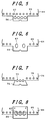
- Fig. 5 to Fig. 8 are plan views showing other examples of tongue portions of the color selection electrodes used in the color cathode ray tube of the present invention.
- Fig. 5 shows the example where stress absorption holes 55 are formed in a skirt portion 54 parallel to stress absorption holes 57 formed in a tongue portion 56.
- Fig. 6 shows the example where stress absorption holes 67 having an elliptical shape are formed in a tongue portion 66.
- numeral 64 indicates a skirt portion and 65 indicates stress absorption holes formed on the skirt portion 64.
- the total opening area of the stress absorption holes 67 is set approximately equal to the total opening area of the stress absorption holes 57 shown in Fig. 5.
- Fig. 7 shows an example where a tongue portion 76 has a proximal portion thereof narrowed compared to a distal end thereof, a fixing portion of the distal end portion has a width sufficient for securing by welding, and the proximal end portion has a structure which can reduce a warp amount of skirt portion 74.
- numeral 75 indicates stress absorption holes.
- Fig. 8 shows an example where a tongue portion 86 which is prepared separately is fixedly secured to a skirt portion 84.
- This separate tongue portion 86 is provided with stress absorption holes 87 and the skirt portion 84 is provided with stress absorption holes 85.
- Fig. 9 shows a shadow mask assembly which is formed by fixedly securing a shadow mask and a mask frame to each other, wherein (a) is a side view, (b) is a plan view, (c) is a cross-sectional view of an essential part showing the securing positions and (d) is a perspective view of a corner portion. Parts which are identical to the parts shown in respective drawings which are described heretofore are given same numerals.
- the skirt portions 24, tongue portions 26 and corners members 28 of the shadow mask 5 are inserted into the inside of the mask frame 6 and the tongue portions 26 and the corner members 28 are fixedly secured to the mask frame 6 at positions indicated by a mark ⁇ by welding, Springs 7 are fixedly secured to respective sides of the mask frame 6 by welding.
- the shape of the mask frame may be provided with a step as shown by a dotted line, for example.
- a warp amount of the skirt portions derived from the spring back after shaping of the shadow mask can be reduced and, furthermore, the occurrence of the displacement derived from the tongue portions after fixedly securing the shadow mask and the mask frame to each other can be prevented whereby the deformation of the shadow mask is suppressed and hence, a color cathode ray tube having an excellent color purity can be obtained.
Landscapes
- Electrodes For Cathode-Ray Tubes (AREA)
Abstract
Description
| specification | diameter of hole (mm) | pitch (mm) | opening rate(%) |
| A | No holes | 0 | 0 |
| B | 5 | 10 | 30 |
| C | 3 | 5 | 35 |
| D | 5 | 8 | 40 |
| opening rate (%) : |
| warping amount of skirt portion after pressing | ||||
| specification | A | B | C | D |
| on long axis | 4.2 | 3.4 | 2.9 | 2.5 |
| on short axis | 4.5 | 3.9 | 3.2 | 2.6 |
| mechanical characteristics after assembling | ||
| Specification | Displacement amount of main surface(mm) | Drop strength (m/s2) |
| A | 0.16 | 216 |
| B | 0.06 | 265 |
| C | 0.02 | 274 |
| D | 0 | 294 |
Claims (13)
- A color cathode ray tube comprising:an evacuated envelope including a panel portion (1) having a phosphor film (4) formed on an inner surface thereof, a neck portion (2) accommodating an electron gun (13), and a funnel portion (3) connecting the neck portion and the panel portion,a color selection electrode including a main surface (21) which faces the phosphor film and in which a plurality of electron beam apertures (22) are formed, skirt portions (24) bent from the main surface in the direction toward the neck portion, and tongue portions (26) which are protruded from the skirt portions in the direction away from the main surface, anda mask frame (6) holding the color selection electrode by fixedly securing the tongue portions,
characterized in that stress absorption hole portions (25) are formed in the tongue portions of the color selection electrode. - A color cathode ray tube comprising:an evacuated envelope including an approximately rectangular panel portion (1) having a phosphor film (14) formed on an inner surface thereof, a neck portion (2) accommodating an electron gun, and a funnel portion (3) connecting the neck portion and the panel portion,an approximately rectangular color selection electrode including a main surface which faces the phosphor film and in which a plurality of electron beam apertures (22) are formed, skirt portions (24) bent from the main surface in the direction toward the neck portion, and tongue portions (26) which are protruded from the skirt portions in the direction away from the main surface anda mask frame (6) holding the color selection electrode by fixedly securing the tongue portions therein,
characterized in that stress absorption hole portions (25) are formed in the tongue portions of the color selection electrode and the equivalent radius of curvature of the main surface along the longitudinal axis is set to equal to or more than 1250 mm. - A color cathode ray tube according to claim 1 or 2, wherein the stress absorption hole portion (25) has a plurality of stress absorption holes (27) formed in the tongue portion (26).
- A color cathode ray tube according to claim 3, wherein stress absorption holes (27) formed in the tongue portion (26) are arranged in the outer peripheral direction of main surface (21).
- A color cathode ray tube according to claim 1 or 2, wherein an opening area of the stress absorption hole portions (25) formed in the tongue portions (26) occupies equal to or more than 25 % of an area of the tongue portions.
- A color cathode ray tube according to claim 1 or 2, wherein the distance from a neck-side end portion of the tongue portions (26) to the stress absorption hole portions (25) is set to equal to or more than 3 mm.
- A color cathode ray tube according to claim 1 or 2, wherein the stress absorption hole portions (25) are formed in the skirt portions (24) of the color selection electrode.
- A color cathode ray tube according to claim 7, wherein the stress absorption hole portions (25) formed in the tongue portions (26) and the stress absorption hole portions formed in the skirt portions (24) are different in dimension.
- A color cathode ray tube according to claim 8, wherein the stress absorption hole portions (25) formed in the tongue portions (26) are larger than the stress absorption hole portions formed in the skirt portions (24) in dimension.
- A color cathode ray tube according to claim 7, wherein the stress absorption hole portions (25) are formed in regions except for corner portions of the color selection electrode and portions disposed at both sides of the corner portions.
- A color cathode ray tube according to claim 1 or 2, wherein the second tongue portions (26) which are protruded from the skirt portions in the direction away from the main surface (21) are provided to the corner portions of the color selection electrode, and the second tongue portions are fixedly secured to the mask frame (6).
- A color cathode ray tube according to claim 7, wherein the stress absorption hole portions formed in the skirt portions are formed in regions except for corner portions of the color selection electrode and portions disposed at both sides of the corner portions.
- A color cathode ray tube comprising:an evacuated envelope including a panel portion (1) having a phosphor film (14) formed on an inner surface thereof, a neck portion (2) accommodating an electron gun, and a funnel portion (3) connecting the neck portion and the panel portion,a color selection electrode including a main surface (21) which faces the phosphor film and in which a plurality of electron beam apertures (22) are formed, skirt portions (24) bent from the main surface in the direction toward the neck portion, and tongue portions (26) which are protruded from the skirt portions in the direction away from the main surface, anda mask frame (6) holding the color selection electrode by fixedly securing the tongue portions,
characterized in that stress absorption hole portions (25) are formed in the tongue portions and the color selection electrode has a region thereof excluding the main surface and portions of tongue portions thinned.
Applications Claiming Priority (2)
| Application Number | Priority Date | Filing Date | Title |
|---|---|---|---|
| JP28803599A JP2001110331A (en) | 1999-10-08 | 1999-10-08 | Color cathode ray tube |
| JP28803599 | 1999-10-08 |
Publications (2)
| Publication Number | Publication Date |
|---|---|
| EP1091381A2 true EP1091381A2 (en) | 2001-04-11 |
| EP1091381A3 EP1091381A3 (en) | 2002-01-02 |
Family
ID=17724992
Family Applications (1)
| Application Number | Title | Priority Date | Filing Date |
|---|---|---|---|
| EP00121217A Withdrawn EP1091381A3 (en) | 1999-10-08 | 2000-09-29 | Color cathode ray tube |
Country Status (6)
| Country | Link |
|---|---|
| US (1) | US6501214B1 (en) |
| EP (1) | EP1091381A3 (en) |
| JP (1) | JP2001110331A (en) |
| KR (1) | KR100345633B1 (en) |
| CN (1) | CN1157750C (en) |
| TW (1) | TW556242B (en) |
Cited By (3)
| Publication number | Priority date | Publication date | Assignee | Title |
|---|---|---|---|---|
| EP1258904A1 (en) * | 2001-05-01 | 2002-11-20 | Hitachi, Ltd. | Color cathode ray tube having flat outer face |
| WO2006072719A1 (en) * | 2004-12-29 | 2006-07-13 | Thomson Licensing | Shadow mask structure for cathode ray tube |
| WO2006091267A3 (en) * | 2005-02-24 | 2007-01-18 | Thomson Licensing | Cathode ray tube having shadow mask with instant geometric thermal transition compensation |
Families Citing this family (13)
| Publication number | Priority date | Publication date | Assignee | Title |
|---|---|---|---|---|
| JP2002260547A (en) * | 2001-02-27 | 2002-09-13 | Toshiba Corp | Color cathode ray tube |
| JP3882514B2 (en) * | 2001-03-08 | 2007-02-21 | 松下電器産業株式会社 | Color cathode ray tube |
| KR100830973B1 (en) * | 2001-11-02 | 2008-05-20 | 삼성에스디아이 주식회사 | Cathode ray tube with shadow mask with improved buffer |
| KR100525902B1 (en) * | 2003-08-25 | 2005-11-04 | 엘지.필립스 디스플레이 주식회사 | Shadow Mask of Cathode Ray Tube |
| US7187113B2 (en) * | 2003-09-17 | 2007-03-06 | Lg.Philips Displays Korea Co., Ltd. | Color cathode ray tube correcting beam landing errors |
| US7199512B2 (en) * | 2003-09-17 | 2007-04-03 | Lg. Philips Displays Korea Co., Ltd. | Color cathode ray tube |
| US7105995B2 (en) * | 2003-09-17 | 2006-09-12 | Lg.Philips Display Co., Ltd. | Color cathode ray tube |
| KR20050049020A (en) * | 2003-11-20 | 2005-05-25 | 엘지.필립스 디스플레이 주식회사 | Color cathode-ray tube |
| KR101784467B1 (en) * | 2011-01-10 | 2017-10-12 | 삼성디스플레이 주식회사 | Mask stick and the assembling method for mask frame assembly using the same |
| KR20120123918A (en) * | 2011-05-02 | 2012-11-12 | 삼성디스플레이 주식회사 | Mask stick and method for assembling mask frame assembly using the same |
| KR101813549B1 (en) * | 2011-05-06 | 2018-01-02 | 삼성디스플레이 주식회사 | Mask stick and assembling apparatus for a mask frame assembly including the mask stick |
| CN103025099B (en) * | 2011-09-26 | 2016-08-10 | 海尔集团公司 | Display backplane and the display screen with this backboard |
| CN102931189B (en) * | 2012-11-01 | 2016-12-21 | 京东方科技集团股份有限公司 | Array base palte and make and method for maintaining, display device |
Family Cites Families (8)
| Publication number | Priority date | Publication date | Assignee | Title |
|---|---|---|---|---|
| GB1407608A (en) * | 1971-09-03 | 1975-09-24 | Hitachi Ltd | Colour picture tubes |
| DE2407295A1 (en) * | 1973-02-16 | 1974-08-22 | Hitachi Ltd | COLOR TUBE WITH IMPROVED SHADOW MASK |
| US4767962A (en) * | 1986-07-02 | 1988-08-30 | Zenith Electronics Corporation | Color cathode ray tube and tensible shadow mask blank for use therein |
| US4942333A (en) | 1988-12-05 | 1990-07-17 | North American Philips Corporation | Shadow mask with border pattern |
| JPH08298078A (en) * | 1995-04-28 | 1996-11-12 | Toshiba Corp | Color picture tube |
| JPH0935657A (en) * | 1995-07-17 | 1997-02-07 | Hitachi Ltd | Shadow mask type color cathode ray tube |
| KR100213764B1 (en) * | 1996-11-13 | 1999-08-02 | 구자홍 | Shadow mask structure of flat CRT |
| KR100279758B1 (en) * | 1997-03-14 | 2001-03-02 | 니시무로 타이죠 | Colored cathode ray tube |
-
1999
- 1999-10-08 JP JP28803599A patent/JP2001110331A/en active Pending
-
2000
- 2000-09-29 EP EP00121217A patent/EP1091381A3/en not_active Withdrawn
- 2000-10-03 TW TW089120577A patent/TW556242B/en active
- 2000-10-04 US US09/679,169 patent/US6501214B1/en not_active Expired - Fee Related
- 2000-10-05 CN CNB00128584XA patent/CN1157750C/en not_active Expired - Fee Related
- 2000-10-07 KR KR1020000059007A patent/KR100345633B1/en not_active Expired - Fee Related
Cited By (4)
| Publication number | Priority date | Publication date | Assignee | Title |
|---|---|---|---|---|
| EP1258904A1 (en) * | 2001-05-01 | 2002-11-20 | Hitachi, Ltd. | Color cathode ray tube having flat outer face |
| US6590327B2 (en) | 2001-05-01 | 2003-07-08 | Hitachi Ltd. | Color cathode ray tube having flat outer face |
| WO2006072719A1 (en) * | 2004-12-29 | 2006-07-13 | Thomson Licensing | Shadow mask structure for cathode ray tube |
| WO2006091267A3 (en) * | 2005-02-24 | 2007-01-18 | Thomson Licensing | Cathode ray tube having shadow mask with instant geometric thermal transition compensation |
Also Published As
| Publication number | Publication date |
|---|---|
| CN1157750C (en) | 2004-07-14 |
| KR20010040025A (en) | 2001-05-15 |
| US6501214B1 (en) | 2002-12-31 |
| KR100345633B1 (en) | 2002-07-24 |
| CN1293444A (en) | 2001-05-02 |
| TW556242B (en) | 2003-10-01 |
| EP1091381A3 (en) | 2002-01-02 |
| JP2001110331A (en) | 2001-04-20 |
Similar Documents
| Publication | Publication Date | Title |
|---|---|---|
| US6501214B1 (en) | Color cathode ray tube | |
| EP0304922B1 (en) | Color cathode ray tube | |
| EP0655762B1 (en) | Color cathode-ray tube | |
| US6441566B2 (en) | Color cathode ray tube and color picture tube apparatus having the same | |
| US6650036B2 (en) | Color cathode ray tube having a radius of curvature ratio relationship | |
| US6552481B2 (en) | Color cathode ray tube having deformation-resistant shadow mask | |
| US6326722B1 (en) | Color cathode-ray tube | |
| US6686684B2 (en) | Color selection electrode implementing a temperature based tension reduction of a shadow mask | |
| US6218772B1 (en) | Color cathode-ray tube with shadow mask mounting system | |
| US6225735B1 (en) | Shadow mask for color cathode-ray tube and method of manufacturing the same | |
| US6707242B2 (en) | Color cathode ray tube | |
| US6274975B1 (en) | Color picture tube having a tension mask attached to a frame | |
| EP0677863B1 (en) | Color cathode ray tube | |
| US5982084A (en) | Color cathode ray tube | |
| EP1001446A1 (en) | Color crt, elastic supporter for color crt and elastic support mechanism | |
| US20060022571A1 (en) | Cathode ray tube | |
| US6707241B2 (en) | Color cathode-ray tube | |
| US7450842B2 (en) | Manufacturing method of color cathode ray tube | |
| CN100364033C (en) | cathode ray tube | |
| EP0818800A1 (en) | Color cathode ray tube | |
| JP2002245950A (en) | Color cathode ray tube | |
| JP2006504237A (en) | Display device having flat display panel | |
| JP2003031148A (en) | Color cathode ray tube and mask frame | |
| JPWO1997031388A1 (en) | color cathode ray tube | |
| JP2003036799A (en) | Color cathode ray tube |
Legal Events
| Date | Code | Title | Description |
|---|---|---|---|
| PUAI | Public reference made under article 153(3) epc to a published international application that has entered the european phase |
Free format text: ORIGINAL CODE: 0009012 |
|
| AK | Designated contracting states |
Kind code of ref document: A2 Designated state(s): AT BE CH CY DE DK ES FI FR GB GR IE IT LI LU MC NL PT SE Kind code of ref document: A2 Designated state(s): DE FR GB IT |
|
| AX | Request for extension of the european patent |
Free format text: AL;LT;LV;MK;RO;SI |
|
| PUAL | Search report despatched |
Free format text: ORIGINAL CODE: 0009013 |
|
| AK | Designated contracting states |
Kind code of ref document: A3 Designated state(s): AT BE CH CY DE DK ES FI FR GB GR IE IT LI LU MC NL PT SE |
|
| AX | Request for extension of the european patent |
Free format text: AL;LT;LV;MK;RO;SI |
|
| RIC1 | Information provided on ipc code assigned before grant |
Free format text: 7H 01J 29/07 A, 7H 01J 31/20 B |
|
| 17P | Request for examination filed |
Effective date: 20020430 |
|
| AKX | Designation fees paid |
Free format text: DE FR GB IT |
|
| STAA | Information on the status of an ep patent application or granted ep patent |
Free format text: STATUS: THE APPLICATION IS DEEMED TO BE WITHDRAWN |
|
| 18D | Application deemed to be withdrawn |
Effective date: 20060523 |