EP1091140A2 - Air Damper - Google Patents
Air Damper Download PDFInfo
- Publication number
- EP1091140A2 EP1091140A2 EP00308772A EP00308772A EP1091140A2 EP 1091140 A2 EP1091140 A2 EP 1091140A2 EP 00308772 A EP00308772 A EP 00308772A EP 00308772 A EP00308772 A EP 00308772A EP 1091140 A2 EP1091140 A2 EP 1091140A2
- Authority
- EP
- European Patent Office
- Prior art keywords
- cylinder
- piston
- string
- air damper
- moved
- Prior art date
- Legal status (The legal status is an assumption and is not a legal conclusion. Google has not performed a legal analysis and makes no representation as to the accuracy of the status listed.)
- Granted
Links
- 239000012530 fluid Substances 0.000 claims 1
- 230000000694 effects Effects 0.000 description 1
- 238000000034 method Methods 0.000 description 1
- 238000012986 modification Methods 0.000 description 1
- 230000004048 modification Effects 0.000 description 1
- 230000002093 peripheral effect Effects 0.000 description 1
Images

Classifications
-
- F—MECHANICAL ENGINEERING; LIGHTING; HEATING; WEAPONS; BLASTING
- F16—ENGINEERING ELEMENTS AND UNITS; GENERAL MEASURES FOR PRODUCING AND MAINTAINING EFFECTIVE FUNCTIONING OF MACHINES OR INSTALLATIONS; THERMAL INSULATION IN GENERAL
- F16F—SPRINGS; SHOCK-ABSORBERS; MEANS FOR DAMPING VIBRATION
- F16F9/00—Springs, vibration-dampers, shock-absorbers, or similarly-constructed movement-dampers using a fluid or the equivalent as damping medium
-
- F—MECHANICAL ENGINEERING; LIGHTING; HEATING; WEAPONS; BLASTING
- F16—ENGINEERING ELEMENTS AND UNITS; GENERAL MEASURES FOR PRODUCING AND MAINTAINING EFFECTIVE FUNCTIONING OF MACHINES OR INSTALLATIONS; THERMAL INSULATION IN GENERAL
- F16F—SPRINGS; SHOCK-ABSORBERS; MEANS FOR DAMPING VIBRATION
- F16F9/00—Springs, vibration-dampers, shock-absorbers, or similarly-constructed movement-dampers using a fluid or the equivalent as damping medium
- F16F9/02—Springs, vibration-dampers, shock-absorbers, or similarly-constructed movement-dampers using a fluid or the equivalent as damping medium using gas only or vacuum
- F16F9/0209—Telescopic
- F16F9/0218—Mono-tubular units
-
- F—MECHANICAL ENGINEERING; LIGHTING; HEATING; WEAPONS; BLASTING
- F16—ENGINEERING ELEMENTS AND UNITS; GENERAL MEASURES FOR PRODUCING AND MAINTAINING EFFECTIVE FUNCTIONING OF MACHINES OR INSTALLATIONS; THERMAL INSULATION IN GENERAL
- F16F—SPRINGS; SHOCK-ABSORBERS; MEANS FOR DAMPING VIBRATION
- F16F9/00—Springs, vibration-dampers, shock-absorbers, or similarly-constructed movement-dampers using a fluid or the equivalent as damping medium
- F16F9/32—Details
- F16F9/54—Arrangements for attachment
-
- F—MECHANICAL ENGINEERING; LIGHTING; HEATING; WEAPONS; BLASTING
- F16—ENGINEERING ELEMENTS AND UNITS; GENERAL MEASURES FOR PRODUCING AND MAINTAINING EFFECTIVE FUNCTIONING OF MACHINES OR INSTALLATIONS; THERMAL INSULATION IN GENERAL
- F16F—SPRINGS; SHOCK-ABSORBERS; MEANS FOR DAMPING VIBRATION
- F16F2224/00—Materials; Material properties
- F16F2224/04—Fluids
- F16F2224/046—Fluids pneumatic
Definitions
- the present invention relates to improvement of a cylinder-type air damper to be employed for, for example, a glove box of an automobile.
- the air damper is composed of a tubular cylinder with both opened ends, a piston which is connected with an end of a string for moving in the cylinder, a valve device which is installed at one end of the cylinder for controlling a passing amount of air, a guide cap which is installed at the other end of the cylinder for guiding the string, and a compressed coil spring which is interposed between the guide cap and the piston in the cylinder.
- This conventional air damper has an advantage of ensuring smoothly opening or closing motion of a glove box.
- an amount of the string to be pulled out of the cylinder corresponds to a movement amount of the piston in the cylinder.
- An object of the invention is to provide an air damper which allows an installment space of a cylinder to be reduced.
- an air damper as follows.
- a tubular cylinder has a first end and a second end.
- a piston is to be moved in the cylinder.
- a compressed coil spring resiliently biases the piston toward the first end in the cylinder.
- a string is for transmitting a damper function caused by a movement of the piston to a body to be moved. The string to be moved is applied over the piston, extending longitudinally of the cylinder.
- the string has a first end fixed to a movable portion relative to an air damper body, and a second end fixed to the air damper body or an unmovable portion relative to the air damper body.
- the air damper further includes a separating plate at a second end of an air damper body as an entrance and exit for the string.
- the string extends at both sides of the separating plate.
- the piston has a hook body formed with a hook wall in a closed annular shape for applying the string over and supports the hook body to be rotated.
- the cylinder is provided with an installment piece fixed to a fixed portion thereof, and a second end of the string is provided with a clip which is engaged with the installment piece and is fixed to the fixed portion together with the installment piece.
- an air damper as follows.
- the damper includes a cylinder longitudinally with a first end and a second end; a piston to be moved longitudinally in the cylinder; and a string which is applied over the piston in the cylinder and extends longitudinally of the cylinder.
- the air damper further includes a spring which biases the piston toward the first end of the cylinder.
- the air damper further includes a separating plate at the second end of the cylinder.
- the string extends at both sides of the separating plate.
- the piston has a hook body to be rotated.
- the string is applied over the hook body.
- the string to be moved is applied over the piston, and, comparing with conventional ones, even in a small-sized air damper, an amount of the string to be pulled out of the cylinder is further long, thus providing a necessary damper stroke.
- the first end of the string is fixed to a movable portion relative to the air damper body and the second end is fixed to the air damper body or an unmovable portion relative to the air damper body, so that, comparing with conventional ones, even in a small-sized air damper, an amount of the string to be pulled out of the cylinder is further longer, thus providing a necessary damper stroke.
- the separating plate is provided at a second end of an air damper body as an entrance and exit for the string, so that a twist of the string outside the air damper body is prevented from spreading inside the air damper body, and a twist in the air damper body is adjusted by pulling the string.
- the string is applied over the closed annular hook wall of the hook body, so that the string can not be not off the hook body, and the hook body rotates relative to the piston to further effectively adjust a twist of the string in the cylinder.
- the second end of the string is provided with the clip, and the second end of the string is easily connected to the installment piece on a side of the cylinder.
- an air damper is composed of a tubular cylinder 1 with both opened ends, a piston 2 to move in the cylinder 1, an end cap with a valve 4 for opening or closing a through hole 3 for air pressure controlling which is opened at first end la of the cylinder 1, a guide cap 6 for guiding a movement of a string 8 as will be described later at the second end 1b of the cylinder 1, a compressed coil spring interposed between the guide cap 6 and the piston 2 for resiliently biasing the piston 2 toward the first end la of the cylinder 1, and a string 8 for transmitting a damper function caused by a movement of the piston 2 to a body to be moved such as a glove box.
- These parts constitute an air damper body.
- the cylinder 1 has installment pieces 9 with screwed holes 9a longitudinally extending integrally at respective outer surfaces close to the first end la and the second end 1b thereof. Particularly, doubled installment pieces 9 on the second end 1b is to be engaged with a second clip 18 which is fixed to a second end 8b of the string 8 as will be described later, thus to be fixed to a portion of the cylinder 1 with the second clip 18.
- the piston 2 has an O-ring 10 fitted in a circumferential face thereof. As shown on Figs. 2 and 3, on a side to be combinedly used as an installment seat of the coil spring 7, it has the tubular connecting part 11 extending integrally therewith.
- the tubular connecting part 11 has a pair of resilient lock-pawls 12 formed on opposed side walls via slits 13. With the connecting part 11, the lock-pawls 12 engages into locking state, and a hook body 14 to be described later is rotatably supported.
- the hook body 14 as shown on the Fig.3, has a cylindrical shape with a hollow inside part. It has an annular projection 15 formed at a central part thereof for engaging with the lock-pawls 12 to be locked. It has a closed annular hook wall 16 formed on a rear end for applying a folded portion of the string 8 to be moved over the hook wall 16.
- the string 8 to be moved is applied over the hook wall 16 of the hook body 14, thus being folded, or extending, in a longitudinal direction of the cylinder 1.
- a first end 8a thereof is secure to a first clip 17 to be fixed on a side face of a glove box of an automobile.
- a second end 8b thereof is secured to a second clip 18 to be engaged with the installment piece 9.
- the second clip 18 has a screwed hole 18a to be engaged with the above-described installment piece 9 and corresponds to the screwed hole 9a of the installment piece 9.
- the guide cap 6 fitted in the second end 1b of the cylinder 1, as shown on Fig. 4, has an arc-shaped guide face 6a for guiding the string 8.
- a separating plate 19 is provided integrally, and the string 8 extends at both sides of the separating plate 19.
- the string 8 is applied over the hook wall 16 configured in a closed annular shape, being folded.
- the hook body 14 is fitted into the tubular connecting part 11 of the piston 2, and the piston 2 is pushed in the cylinder 1 with the coil spring 7.
- the guide cap 6 is fitted in the second end 1b of the cylinder 1.
- the first end 8a of the string 8 is secured to the first clip 17 and the second end 8b of the string 8 is secured to the second clip 18.
- the second clip 18 is engaged with the installment piece 9 of the cylinder 1, and, as shown on Fig. 5, the air damper of one-way method is easily assembled.
- the cylinder 1 In the case of employment for a glove box of an automobile, in the same conventional manner, the cylinder 1 is fixed to an instrument panel side by screwing its installment piece 9 and the second clip 18 as not specifically shown in Figs. While pulling the first end 8a of the string 8 extending from the guide cap 6, the first end 8a is connected to the glove box side by the first clip 17, thus securing opening or closing motion of the glove box.
- the string 8 In the operation for connecting to the glove box, the string 8 is movably applied over the hook body 14 of the hook wall 16, extending longitudinally of the cylinder 1, and a pulled-out amount of the first end 8a of the string 8 is approximately twice as long as movement amount of the piston 2.
- the separating plate 19 When opening or closing the glove box, the separating plate 19 is on the second end 1b of the cylinder 1 corresponding to an entrance and exit of the string 8. A twist of the string 8 outside the cylinder 1 is prevented from spreading in the cylinder 1 and a twist of the string 8 in the cylinder 1 is adjusted by pulling the string 8. In addition, the string 8 is applied over the closed annular hook wall 16 of the hook body 14, so that the string 8 can not be off the hook body 14 and that rotating the hook body 14 relative to the piston 2 makes the twist of the string 8 in the cylinder 1 being adjusted further effectively.
- the cylinder 1 is fixed to the instrument panel side and the first end 8a of the string 8 is connected to a glove box side as a movable body.
- the cylinder 1 may be fixed to the glove box side and the first end 8a of the string 8 may be connected to the instrument panel side as a peripheral portion of the glove box, according to practice.
- the second end 8b of the string 8 can be connected to a portion for fixing the cylinder 1 itself.
- connecting the second end 8b of the string 8 to the cylinder 1 by the second clip 18 makes its connection operation much easier.
- the second end 8b of the string 8 can be connected to the guide cap 6 or its separating plate 19.
Landscapes
- Engineering & Computer Science (AREA)
- General Engineering & Computer Science (AREA)
- Mechanical Engineering (AREA)
- Vehicle Step Arrangements And Article Storage (AREA)
- Fluid-Damping Devices (AREA)
- Crystals, And After-Treatments Of Crystals (AREA)
Abstract
Description
- The present invention relates to improvement of a cylinder-type air damper to be employed for, for example, a glove box of an automobile.
- There has been disclosed in Japanese Utility Model Registration Publication No. 2557064 a conventional air damper of such a structure.
- The air damper is composed of a tubular cylinder with both opened ends, a piston which is connected with an end of a string for moving in the cylinder, a valve device which is installed at one end of the cylinder for controlling a passing amount of air, a guide cap which is installed at the other end of the cylinder for guiding the string, and a compressed coil spring which is interposed between the guide cap and the piston in the cylinder.
- This conventional air damper has an advantage of ensuring smoothly opening or closing motion of a glove box. On the contrary, an amount of the string to be pulled out of the cylinder corresponds to a movement amount of the piston in the cylinder. Thus, in a place to be installed where the cylinder can not take at a large length thereof, there is a disadvantage of not taking a necessary damper stroke.
- An object of the invention is to provide an air damper which allows an installment space of a cylinder to be reduced.
- From a first aspect of the present invention, there is provided an air damper as follows. In the air damper, a tubular cylinder has a first end and a second end. A piston is to be moved in the cylinder. A compressed coil spring resiliently biases the piston toward the first end in the cylinder. A string is for transmitting a damper function caused by a movement of the piston to a body to be moved. The string to be moved is applied over the piston, extending longitudinally of the cylinder.
- Preferably, the string has a first end fixed to a movable portion relative to an air damper body, and a second end fixed to the air damper body or an unmovable portion relative to the air damper body.
- Preferably, the air damper further includes a separating plate at a second end of an air damper body as an entrance and exit for the string. The string extends at both sides of the separating plate.
- Preferably, the piston has a hook body formed with a hook wall in a closed annular shape for applying the string over and supports the hook body to be rotated.
- Preferably, the cylinder is provided with an installment piece fixed to a fixed portion thereof, and a second end of the string is provided with a clip which is engaged with the installment piece and is fixed to the fixed portion together with the installment piece.
- From a second aspect of the present invention, there is provided an air damper as follows. The damper includes a cylinder longitudinally with a first end and a second end; a piston to be moved longitudinally in the cylinder; and a string which is applied over the piston in the cylinder and extends longitudinally of the cylinder.
- Preferably, the air damper further includes a spring which biases the piston toward the first end of the cylinder.
- Preferably, the air damper further includes a separating plate at the second end of the cylinder. The string extends at both sides of the separating plate.
- Preferably, the piston has a hook body to be rotated. The string is applied over the hook body.
- According to the invention, the string to be moved is applied over the piston, and, comparing with conventional ones, even in a small-sized air damper, an amount of the string to be pulled out of the cylinder is further long, thus providing a necessary damper stroke.
- The first end of the string is fixed to a movable portion relative to the air damper body and the second end is fixed to the air damper body or an unmovable portion relative to the air damper body, so that, comparing with conventional ones, even in a small-sized air damper, an amount of the string to be pulled out of the cylinder is further longer, thus providing a necessary damper stroke.
- The separating plate is provided at a second end of an air damper body as an entrance and exit for the string, so that a twist of the string outside the air damper body is prevented from spreading inside the air damper body, and a twist in the air damper body is adjusted by pulling the string.
- The string is applied over the closed annular hook wall of the hook body, so that the string can not be not off the hook body, and the hook body rotates relative to the piston to further effectively adjust a twist of the string in the cylinder.
- The second end of the string is provided with the clip, and the second end of the string is easily connected to the installment piece on a side of the cylinder.
-
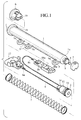
- Fig. 1 is an exploded perspective view of an air damper of an embodiment according to the invention;
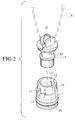
- Fig. 2 is an exploded perspective view showing a relationship of a piston and a hook body;
- Fig. 3 is a sectional view showing a state where a hook body to be rotated is supported to a piston;
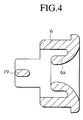
- Fig. 4 is a cross sectional view of a guide cap; and
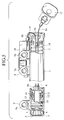
- Fig. 5 is a front view partially broken away showing an assembled air damper.
-
- A preferred embodiment of the present invention will be hereby explained with reference to the drawings.
- As shown on Fig. 1, an air damper is composed of a
tubular cylinder 1 with both opened ends, apiston 2 to move in thecylinder 1, an end cap with avalve 4 for opening or closing a throughhole 3 for air pressure controlling which is opened at first end la of thecylinder 1, aguide cap 6 for guiding a movement of astring 8 as will be described later at thesecond end 1b of thecylinder 1, a compressed coil spring interposed between theguide cap 6 and thepiston 2 for resiliently biasing thepiston 2 toward the first end la of thecylinder 1, and astring 8 for transmitting a damper function caused by a movement of thepiston 2 to a body to be moved such as a glove box. These parts constitute an air damper body. - The
cylinder 1 hasinstallment pieces 9 with screwedholes 9a longitudinally extending integrally at respective outer surfaces close to the first end la and thesecond end 1b thereof. Particularly, doubledinstallment pieces 9 on thesecond end 1b is to be engaged with asecond clip 18 which is fixed to asecond end 8b of thestring 8 as will be described later, thus to be fixed to a portion of thecylinder 1 with thesecond clip 18. - The
piston 2 has an O-ring 10 fitted in a circumferential face thereof. As shown on Figs. 2 and 3, on a side to be combinedly used as an installment seat of thecoil spring 7, it has the tubular connectingpart 11 extending integrally therewith. The tubular connectingpart 11 has a pair of resilient lock-pawls 12 formed on opposed side walls viaslits 13. With the connectingpart 11, the lock-pawls 12 engages into locking state, and ahook body 14 to be described later is rotatably supported. - The
hook body 14, as shown on the Fig.3, has a cylindrical shape with a hollow inside part. It has anannular projection 15 formed at a central part thereof for engaging with the lock-pawls 12 to be locked. It has a closedannular hook wall 16 formed on a rear end for applying a folded portion of thestring 8 to be moved over thehook wall 16. - The
string 8 to be moved is applied over thehook wall 16 of thehook body 14, thus being folded, or extending, in a longitudinal direction of thecylinder 1. Afirst end 8a thereof is secure to afirst clip 17 to be fixed on a side face of a glove box of an automobile. Asecond end 8b thereof is secured to asecond clip 18 to be engaged with theinstallment piece 9. Particularly, thesecond clip 18 has ascrewed hole 18a to be engaged with the above-describedinstallment piece 9 and corresponds to thescrewed hole 9a of theinstallment piece 9. - The
guide cap 6 fitted in thesecond end 1b of thecylinder 1, as shown on Fig. 4, has an arc-shaped guide face 6a for guiding thestring 8. Inside thesecond end 1b of thecylinder 1, aseparating plate 19 is provided integrally, and thestring 8 extends at both sides of theseparating plate 19. - When assembling the air damper with the constitution, at first, the
string 8 is applied over thehook wall 16 configured in a closed annular shape, being folded. Thehook body 14 is fitted into the tubular connectingpart 11 of thepiston 2, and thepiston 2 is pushed in thecylinder 1 with thecoil spring 7. While pulling thefirst end 8a and thesecond end 8b of the foldedstring 8 through theguide cap 6, theguide cap 6 is fitted in thesecond end 1b of thecylinder 1. Thefirst end 8a of thestring 8 is secured to thefirst clip 17 and thesecond end 8b of thestring 8 is secured to thesecond clip 18. Thesecond clip 18 is engaged with theinstallment piece 9 of thecylinder 1, and, as shown on Fig. 5, the air damper of one-way method is easily assembled. - In the case of employment for a glove box of an automobile, in the same conventional manner, the
cylinder 1 is fixed to an instrument panel side by screwing itsinstallment piece 9 and thesecond clip 18 as not specifically shown in Figs. While pulling thefirst end 8a of thestring 8 extending from theguide cap 6, thefirst end 8a is connected to the glove box side by thefirst clip 17, thus securing opening or closing motion of the glove box. In the operation for connecting to the glove box, thestring 8 is movably applied over thehook body 14 of thehook wall 16, extending longitudinally of thecylinder 1, and a pulled-out amount of thefirst end 8a of thestring 8 is approximately twice as long as movement amount of thepiston 2. Thus, if it is employed for ones whose installment space for the air damper body is limited and, in addition, which require a comparatively long stroke, comparing with a conventional air damper with a longitudinal length identical to thecylinder 1, a twice longer damper stroke is obtained, so that a sufficient correspondence can be performed. - When the glove box is moved in an opening direction, according to the movement, the
string 8 is pulled gradually out of thecylinder 1, and thepiston 2 is moved in the same direction against a spring pressure of thecoil spring 7. As a result, by a flow resistance of air passing through anorifice 2a, a damper effect is obtained, and it is ensured that the glove box is moved slowly toward open state. - On the other hand, when the glove box is moved in a closing direction, the
piston 2 is forced to be pushed back in thecylinder 1 with thestring 8 by a spring pressure of thecoil spring 7. - An air which has been accumulated in the
cylinder 1 is relieved from theend cap 5 to outside through thehole 3 opened by thevalve 4. Thus, thepiston 2 moves quickly in thecylinder 1, and a closing motion of the glove box is accelerated. - When opening or closing the glove box, the separating
plate 19 is on thesecond end 1b of thecylinder 1 corresponding to an entrance and exit of thestring 8. A twist of thestring 8 outside thecylinder 1 is prevented from spreading in thecylinder 1 and a twist of thestring 8 in thecylinder 1 is adjusted by pulling thestring 8. In addition, thestring 8 is applied over the closedannular hook wall 16 of thehook body 14, so that thestring 8 can not be off thehook body 14 and that rotating thehook body 14 relative to thepiston 2 makes the twist of thestring 8 in thecylinder 1 being adjusted further effectively. - In the above-described embodiment, the
cylinder 1 is fixed to the instrument panel side and thefirst end 8a of thestring 8 is connected to a glove box side as a movable body. On the contrary, thecylinder 1 may be fixed to the glove box side and thefirst end 8a of thestring 8 may be connected to the instrument panel side as a peripheral portion of the glove box, according to practice. Without being connected to theinstallment piece 9, thesecond end 8b of thestring 8 can be connected to a portion for fixing thecylinder 1 itself. In addition, as shown by the embodiment, connecting thesecond end 8b of thestring 8 to thecylinder 1 by thesecond clip 18 makes its connection operation much easier. Thesecond end 8b of thestring 8 can be connected to theguide cap 6 or itsseparating plate 19. - Although the invention has been described above by reference to certain embodiments of the invention, the invention is not limited to the embodiments described above. Modifications and variations of the embodiments described above will occur to those skilled in the art, in light of the above teachings.
Claims (10)
- An air damper comprising:a tubular cylinder having a first end and a second end;a piston to be moved in the cylinder;a compressed coil spring resiliently biasing the piston toward the first end in the cylinder; anda string for transmitting a damper function caused by a movement of the piston to a body to be moved, the string to be moved being applied over the piston, extending longitudinally of the cylinder.
- An air damper according to claim 1,
wherein the string has a first end fixed to a movable portion relative to an air damper body, and a second end fixed to the air damper body or an unmovable portion relative to the air damper body. - An air damper according to claim 1, further comprising:
a separating plate at a second end of an air damper body as an entrance and exit for the string,
wherein the string extends at both sides of the separating plate. - An air damper according to claim 1,
wherein the piston has a hook body formed with a hook wall in a closed annular shape for applying the string over and supports the hook body to be rotated. - An air damper according to claim 1,
wherein the cylinder is provided with an installment piece fixed to a fixed portion thereof, and a second end of the string is provided with a clip which is engaged with the installment piece and is fixed to the fixed portion together with the installment piece. - An air damper comprising:a cylinder longitudinally with a first end and a second end;a piston to be moved longitudinally in the cylinder; anda string applied over the piston in the cylinder, extending longitudinally of the cylinder.
- An air damper according to claim 6, further comprising:
a spring biasing the piston toward the first end of the cylinder. - An air damper according to claim 6, further comprising:
a separating plate at the second end of the cylinder,
wherein the string extends at both sides of the separating plate. - An air damper according to claim 6,
wherein the piston has a hook body to be rotated, the string is applied over the hook body. - A damper comprising a piston means mounted in a cylinder means for sliding movement therein, said piston means including vent means for allowing the passage of fluid therethrough; biasing means for biasing said piston in one direction; and a pulling member for pulling the piston in the opposite direction, the arrangement being such that a predetermined linear movement of the pulling member for pulling said member in said opposite direction results in greater linear movement of said piston in said opposite direction.
Applications Claiming Priority (2)
| Application Number | Priority Date | Filing Date | Title |
|---|---|---|---|
| JP28755099 | 1999-10-08 | ||
| JP28755099A JP3475327B2 (en) | 1999-10-08 | 1999-10-08 | Air damper |
Publications (3)
| Publication Number | Publication Date |
|---|---|
| EP1091140A2 true EP1091140A2 (en) | 2001-04-11 |
| EP1091140A3 EP1091140A3 (en) | 2002-04-10 |
| EP1091140B1 EP1091140B1 (en) | 2004-09-22 |
Family
ID=17718801
Family Applications (1)
| Application Number | Title | Priority Date | Filing Date |
|---|---|---|---|
| EP00308772A Expired - Lifetime EP1091140B1 (en) | 1999-10-08 | 2000-10-05 | Air Damper |
Country Status (6)
| Country | Link |
|---|---|
| US (1) | US6367785B1 (en) |
| EP (1) | EP1091140B1 (en) |
| JP (1) | JP3475327B2 (en) |
| KR (1) | KR100406762B1 (en) |
| AT (1) | ATE276898T1 (en) |
| DE (1) | DE60013999T2 (en) |
Families Citing this family (15)
| Publication number | Priority date | Publication date | Assignee | Title |
|---|---|---|---|---|
| US6578833B2 (en) * | 1999-12-10 | 2003-06-17 | Piolax, Inc. | String pull-in device |
| JP3912966B2 (en) * | 2000-08-25 | 2007-05-09 | 株式会社パイオラックス | Air damper |
| JP3994042B2 (en) * | 2002-09-20 | 2007-10-17 | 株式会社パイオラックス | String type air damper |
| AU2004200526B2 (en) * | 2003-02-14 | 2009-01-08 | Hunter Douglas Industries B.V. | Cord tensioner |
| KR20050041521A (en) * | 2003-10-31 | 2005-05-04 | 현대자동차주식회사 | Combination type air damper of glove box in automobile |
| JP4668738B2 (en) * | 2005-08-29 | 2011-04-13 | 株式会社パイオラックス | Air damper and manufacturing method thereof |
| JP4636987B2 (en) * | 2005-10-04 | 2011-02-23 | 株式会社パイオラックス | Air damper |
| JP2011127648A (en) * | 2009-12-16 | 2011-06-30 | Nifco Inc | Damper device |
| CN103438138A (en) * | 2013-08-15 | 2013-12-11 | 苏新文 | Internal small hole air intake stay wire type air damper |
| US9475421B2 (en) | 2013-10-23 | 2016-10-25 | Burton Technologies, Llc | Reflector damper bracket |
| CN103557259A (en) * | 2013-11-14 | 2014-02-05 | 苏新文 | Fall block pulling rope type air damper |
| US10414469B1 (en) * | 2018-12-05 | 2019-09-17 | Steven Smaracko | Spring-loaded wakeboard booster |
| WO2022076967A1 (en) | 2020-10-05 | 2022-04-14 | Asyst Technologies L.L.C. | Adjustable linkage arm |
| KR102684046B1 (en) * | 2022-04-04 | 2024-07-12 | 현대모비스 주식회사 | Damper for glove box in vehicle and glove box having the same |
| JP2025029737A (en) * | 2023-08-22 | 2025-03-07 | 株式会社パイオラックス | Damper Device |
Family Cites Families (14)
| Publication number | Priority date | Publication date | Assignee | Title |
|---|---|---|---|---|
| US1135372A (en) * | 1914-03-27 | 1915-04-13 | Charles Gibson | Flagstaff for golf-links and the like. |
| US2298611A (en) * | 1940-05-18 | 1942-10-13 | Douglas Aircraft Co Inc | Tension compensating device |
| US2856077A (en) * | 1954-10-08 | 1958-10-14 | Jr Ray W Stanton | Tensioning devices |
| US3389422A (en) * | 1965-10-22 | 1968-06-25 | Fabmagic Inc | Spring motor door closer |
| US4003102A (en) * | 1975-08-07 | 1977-01-18 | Elmer E. Jones | Door and window closer |
| GB8511370D0 (en) * | 1985-05-03 | 1985-06-12 | Robertson M S | Garden/sun umbrellas |
| DE3818152A1 (en) * | 1988-05-28 | 1989-12-07 | Stabilus Gmbh | TENNIS RACKET |
| US4854541A (en) * | 1988-08-08 | 1989-08-08 | Iowa State University Research Foundation, Inc. | Power line support |
| US4955309A (en) * | 1989-05-08 | 1990-09-11 | International Nautical Supplies, Inc. | Yieldable line assembly and in line shock absorber |
| JP2557064Y2 (en) * | 1992-03-25 | 1997-12-08 | 株式会社パイオラックス | Structure of damper device such as storage box |
| US5845749A (en) * | 1995-10-11 | 1998-12-08 | Tmj Properties, L.L.C. | Linear motion absorber with synthetic components |
| US5694879A (en) * | 1996-08-05 | 1997-12-09 | Taylor; James | Boat docking apparatus |
| US5906173A (en) * | 1998-06-10 | 1999-05-25 | Day, Jr.; Charlie E | Anchor line shock absorber |
| JP3321665B2 (en) * | 1998-11-06 | 2002-09-03 | 株式会社パイオラックス | Air damper |
-
1999
- 1999-10-08 JP JP28755099A patent/JP3475327B2/en not_active Expired - Lifetime
-
2000
- 2000-10-05 AT AT00308772T patent/ATE276898T1/en not_active IP Right Cessation
- 2000-10-05 DE DE60013999T patent/DE60013999T2/en not_active Expired - Lifetime
- 2000-10-05 EP EP00308772A patent/EP1091140B1/en not_active Expired - Lifetime
- 2000-10-06 US US09/684,526 patent/US6367785B1/en not_active Expired - Lifetime
- 2000-10-07 KR KR10-2000-0059033A patent/KR100406762B1/en not_active Expired - Fee Related
Non-Patent Citations (1)
| Title |
|---|
| None |
Also Published As
| Publication number | Publication date |
|---|---|
| KR100406762B1 (en) | 2003-11-21 |
| JP2001108002A (en) | 2001-04-20 |
| JP3475327B2 (en) | 2003-12-08 |
| KR20010050914A (en) | 2001-06-25 |
| EP1091140A3 (en) | 2002-04-10 |
| EP1091140B1 (en) | 2004-09-22 |
| DE60013999D1 (en) | 2004-10-28 |
| US6367785B1 (en) | 2002-04-09 |
| DE60013999T2 (en) | 2006-02-23 |
| ATE276898T1 (en) | 2004-10-15 |
Similar Documents
| Publication | Publication Date | Title |
|---|---|---|
| EP1091140B1 (en) | Air Damper | |
| JP2557064Y2 (en) | Structure of damper device such as storage box | |
| US4110868A (en) | Air damper | |
| US5749174A (en) | Window regulator with spring retainer | |
| EP1114945B1 (en) | Air damper | |
| US6220583B1 (en) | Air damper with hook on piston | |
| JP3768061B2 (en) | Air damper | |
| JPS6128070B2 (en) | ||
| JP2547912Y2 (en) | Piston cylinder type air damper | |
| EP2634452B1 (en) | Piston damper | |
| WO2001042049A1 (en) | String pull-in device | |
| US5706606A (en) | Device for shutting a sliding door | |
| JPH06330972A (en) | gas spring | |
| JP2594638Y2 (en) | Structure of storage box damper device | |
| KR100232774B1 (en) | Spring door mechanism | |
| KR102327282B1 (en) | Damping apparatus for sliding door | |
| KR102749793B1 (en) | The impact reduction apparatus of the sliding door | |
| JP3036564U (en) | Sliding door closer | |
| KR101232843B1 (en) | Air Damper | |
| KR102029675B1 (en) | Door closer | |
| JP3768048B2 (en) | Box body opening and closing device | |
| JP3491277B2 (en) | Air damper | |
| JPS6237195B2 (en) | ||
| JPS583117B2 (en) | automatic door closing device | |
| GB2398104A (en) | Friction Stay |
Legal Events
| Date | Code | Title | Description |
|---|---|---|---|
| PUAI | Public reference made under article 153(3) epc to a published international application that has entered the european phase |
Free format text: ORIGINAL CODE: 0009012 |
|
| AK | Designated contracting states |
Kind code of ref document: A2 Designated state(s): AT BE CH CY DE DK ES FI FR GB GR IE IT LI LU MC NL PT SE |
|
| AX | Request for extension of the european patent |
Free format text: AL;LT;LV;MK;RO;SI |
|
| PUAL | Search report despatched |
Free format text: ORIGINAL CODE: 0009013 |
|
| AK | Designated contracting states |
Kind code of ref document: A3 Designated state(s): AT BE CH CY DE DK ES FI FR GB GR IE IT LI LU MC NL PT SE |
|
| AX | Request for extension of the european patent |
Free format text: AL;LT;LV;MK;RO;SI |
|
| RIC1 | Information provided on ipc code assigned before grant |
Free format text: 7B 60R 7/06 A, 7F 16F 9/02 B |
|
| 17P | Request for examination filed |
Effective date: 20020918 |
|
| AKX | Designation fees paid |
Free format text: AT BE CH CY DE DK ES FI FR GB GR IE IT LI LU MC NL PT SE |
|
| 17Q | First examination report despatched |
Effective date: 20030812 |
|
| GRAP | Despatch of communication of intention to grant a patent |
Free format text: ORIGINAL CODE: EPIDOSNIGR1 |
|
| GRAS | Grant fee paid |
Free format text: ORIGINAL CODE: EPIDOSNIGR3 |
|
| GRAA | (expected) grant |
Free format text: ORIGINAL CODE: 0009210 |
|
| AK | Designated contracting states |
Kind code of ref document: B1 Designated state(s): AT BE CH CY DE DK ES FI FR GB GR IE IT LI LU MC NL PT SE |
|
| PG25 | Lapsed in a contracting state [announced via postgrant information from national office to epo] |
Ref country code: IT Free format text: LAPSE BECAUSE OF FAILURE TO SUBMIT A TRANSLATION OF THE DESCRIPTION OR TO PAY THE FEE WITHIN THE PRESCRIBED TIME-LIMIT;WARNING: LAPSES OF ITALIAN PATENTS WITH EFFECTIVE DATE BEFORE 2007 MAY HAVE OCCURRED AT ANY TIME BEFORE 2007. THE CORRECT EFFECTIVE DATE MAY BE DIFFERENT FROM THE ONE RECORDED. Effective date: 20040922 Ref country code: AT Free format text: LAPSE BECAUSE OF FAILURE TO SUBMIT A TRANSLATION OF THE DESCRIPTION OR TO PAY THE FEE WITHIN THE PRESCRIBED TIME-LIMIT Effective date: 20040922 Ref country code: BE Free format text: LAPSE BECAUSE OF FAILURE TO SUBMIT A TRANSLATION OF THE DESCRIPTION OR TO PAY THE FEE WITHIN THE PRESCRIBED TIME-LIMIT Effective date: 20040922 Ref country code: CY Free format text: LAPSE BECAUSE OF FAILURE TO SUBMIT A TRANSLATION OF THE DESCRIPTION OR TO PAY THE FEE WITHIN THE PRESCRIBED TIME-LIMIT Effective date: 20040922 Ref country code: FI Free format text: LAPSE BECAUSE OF FAILURE TO SUBMIT A TRANSLATION OF THE DESCRIPTION OR TO PAY THE FEE WITHIN THE PRESCRIBED TIME-LIMIT Effective date: 20040922 Ref country code: CH Free format text: LAPSE BECAUSE OF FAILURE TO SUBMIT A TRANSLATION OF THE DESCRIPTION OR TO PAY THE FEE WITHIN THE PRESCRIBED TIME-LIMIT Effective date: 20040922 Ref country code: NL Free format text: LAPSE BECAUSE OF FAILURE TO SUBMIT A TRANSLATION OF THE DESCRIPTION OR TO PAY THE FEE WITHIN THE PRESCRIBED TIME-LIMIT Effective date: 20040922 Ref country code: LI Free format text: LAPSE BECAUSE OF FAILURE TO SUBMIT A TRANSLATION OF THE DESCRIPTION OR TO PAY THE FEE WITHIN THE PRESCRIBED TIME-LIMIT Effective date: 20040922 |
|
| REG | Reference to a national code |
Ref country code: GB Ref legal event code: FG4D |
|
| REG | Reference to a national code |
Ref country code: CH Ref legal event code: EP |
|
| PG25 | Lapsed in a contracting state [announced via postgrant information from national office to epo] |
Ref country code: IE Free format text: LAPSE BECAUSE OF NON-PAYMENT OF DUE FEES Effective date: 20041005 Ref country code: LU Free format text: LAPSE BECAUSE OF NON-PAYMENT OF DUE FEES Effective date: 20041005 |
|
| REG | Reference to a national code |
Ref country code: IE Ref legal event code: FG4D |
|
| REF | Corresponds to: |
Ref document number: 60013999 Country of ref document: DE Date of ref document: 20041028 Kind code of ref document: P |
|
| PG25 | Lapsed in a contracting state [announced via postgrant information from national office to epo] |
Ref country code: MC Free format text: LAPSE BECAUSE OF NON-PAYMENT OF DUE FEES Effective date: 20041031 |
|
| PG25 | Lapsed in a contracting state [announced via postgrant information from national office to epo] |
Ref country code: DK Free format text: LAPSE BECAUSE OF FAILURE TO SUBMIT A TRANSLATION OF THE DESCRIPTION OR TO PAY THE FEE WITHIN THE PRESCRIBED TIME-LIMIT Effective date: 20041222 Ref country code: SE Free format text: LAPSE BECAUSE OF FAILURE TO SUBMIT A TRANSLATION OF THE DESCRIPTION OR TO PAY THE FEE WITHIN THE PRESCRIBED TIME-LIMIT Effective date: 20041222 Ref country code: GR Free format text: LAPSE BECAUSE OF FAILURE TO SUBMIT A TRANSLATION OF THE DESCRIPTION OR TO PAY THE FEE WITHIN THE PRESCRIBED TIME-LIMIT Effective date: 20041222 |
|
| PG25 | Lapsed in a contracting state [announced via postgrant information from national office to epo] |
Ref country code: ES Free format text: LAPSE BECAUSE OF FAILURE TO SUBMIT A TRANSLATION OF THE DESCRIPTION OR TO PAY THE FEE WITHIN THE PRESCRIBED TIME-LIMIT Effective date: 20050102 |
|
| REG | Reference to a national code |
Ref country code: CH Ref legal event code: PL |
|
| NLV1 | Nl: lapsed or annulled due to failure to fulfill the requirements of art. 29p and 29m of the patents act | ||
| ET | Fr: translation filed | ||
| REG | Reference to a national code |
Ref country code: IE Ref legal event code: MM4A |
|
| PLBE | No opposition filed within time limit |
Free format text: ORIGINAL CODE: 0009261 |
|
| STAA | Information on the status of an ep patent application or granted ep patent |
Free format text: STATUS: NO OPPOSITION FILED WITHIN TIME LIMIT |
|
| 26N | No opposition filed |
Effective date: 20050623 |
|
| PG25 | Lapsed in a contracting state [announced via postgrant information from national office to epo] |
Ref country code: PT Free format text: LAPSE BECAUSE OF NON-PAYMENT OF DUE FEES Effective date: 20050222 |
|
| REG | Reference to a national code |
Ref country code: FR Ref legal event code: PLFP Year of fee payment: 16 |
|
| PGFP | Annual fee paid to national office [announced via postgrant information from national office to epo] |
Ref country code: FR Payment date: 20150908 Year of fee payment: 16 |
|
| REG | Reference to a national code |
Ref country code: FR Ref legal event code: ST Effective date: 20170630 |
|
| PG25 | Lapsed in a contracting state [announced via postgrant information from national office to epo] |
Ref country code: FR Free format text: LAPSE BECAUSE OF NON-PAYMENT OF DUE FEES Effective date: 20161102 |
|
| PGFP | Annual fee paid to national office [announced via postgrant information from national office to epo] |
Ref country code: DE Payment date: 20180925 Year of fee payment: 19 |
|
| PGFP | Annual fee paid to national office [announced via postgrant information from national office to epo] |
Ref country code: GB Payment date: 20181003 Year of fee payment: 19 |
|
| REG | Reference to a national code |
Ref country code: DE Ref legal event code: R119 Ref document number: 60013999 Country of ref document: DE |
|
| PG25 | Lapsed in a contracting state [announced via postgrant information from national office to epo] |
Ref country code: DE Free format text: LAPSE BECAUSE OF NON-PAYMENT OF DUE FEES Effective date: 20200501 |
|
| GBPC | Gb: european patent ceased through non-payment of renewal fee |
Effective date: 20191005 |
|
| PG25 | Lapsed in a contracting state [announced via postgrant information from national office to epo] |
Ref country code: GB Free format text: LAPSE BECAUSE OF NON-PAYMENT OF DUE FEES Effective date: 20191005 |