EP1090810A2 - Infrared sensor for detecting an overtaking vehicle - Google Patents
Infrared sensor for detecting an overtaking vehicle Download PDFInfo
- Publication number
- EP1090810A2 EP1090810A2 EP00830648A EP00830648A EP1090810A2 EP 1090810 A2 EP1090810 A2 EP 1090810A2 EP 00830648 A EP00830648 A EP 00830648A EP 00830648 A EP00830648 A EP 00830648A EP 1090810 A2 EP1090810 A2 EP 1090810A2
- Authority
- EP
- European Patent Office
- Prior art keywords
- fact
- sensor device
- vehicle
- cells
- overtaking
- Prior art date
- Legal status (The legal status is an assumption and is not a legal conclusion. Google has not performed a legal analysis and makes no representation as to the accuracy of the status listed.)
- Withdrawn
Links
Images

Classifications
-
- B—PERFORMING OPERATIONS; TRANSPORTING
- B60—VEHICLES IN GENERAL
- B60R—VEHICLES, VEHICLE FITTINGS, OR VEHICLE PARTS, NOT OTHERWISE PROVIDED FOR
- B60R1/00—Optical viewing arrangements; Real-time viewing arrangements for drivers or passengers using optical image capturing systems, e.g. cameras or video systems specially adapted for use in or on vehicles
- B60R1/12—Mirror assemblies combined with other articles, e.g. clocks
-
- B—PERFORMING OPERATIONS; TRANSPORTING
- B60—VEHICLES IN GENERAL
- B60R—VEHICLES, VEHICLE FITTINGS, OR VEHICLE PARTS, NOT OTHERWISE PROVIDED FOR
- B60R1/00—Optical viewing arrangements; Real-time viewing arrangements for drivers or passengers using optical image capturing systems, e.g. cameras or video systems specially adapted for use in or on vehicles
- B60R1/12—Mirror assemblies combined with other articles, e.g. clocks
- B60R2001/1223—Mirror assemblies combined with other articles, e.g. clocks with sensors or transducers
Definitions
- the present invention refers to infrared sensor devices for motor-vehicles, of the type designed to detect the presence of an overtaking vehicle.
- the invention concerns a device of the type comprising infrared sensors associated with the rear view mirror on the outside of the motor-vehicle and suitable for detecting the infrared radiation emitted by an overtaking vehicle.
- the object of the present invention is a sensor device of the type indicated at the beginning of the present description, characterized by the fact that it includes at least two cells that are sensitive to infrared radiation, placed on one side of the reflecting plate of the outside rear view mirror, behind focusing optics, in which each cell emits a signal that is proportional to the infrared radiation it receives, said device including an electronic circuit that emits a global signal proportional to the difference between the signals produced by the two cells, so that said global signal enables a distinction to be made between the presence of an overtaking vehicle and that of other vehicles travelling in the opposite direction, as well as reducing the likelihood of false alarms due to electronic and electromagnetic noise.
- the above-mentioned cells are pyroelectric sensors that emit a signal proportional to their temperature. Sensors of this type are marketed, for instance, by Heiman, Murata, Nippon Ceramic, etc.
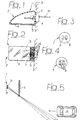
- the numeral 1 indicates a rear view mirror assembly for a motor-vehicle, comprising a body 2 mounted on the side of the vehicle 3, or in the bottom front corner of the side window, and fitted with a reflecting plate 4.
- the constructional details of the mirror 1 and of the way in which said mirror is attached to the motor-vehicle are not described here because they can be achieved in any known manner and they do not form a part of the present invention.
- the reflecting plate 4 there is vertically elongated plate 5 comprising a number of Fresnel lenses 6 serving to focus the infrared radiation emitted by an overtaking vehicle on a sensor 7 comprising a pair of pyroelectric cells 8, each of which is designed to emit an electric signal proportional to its temperature.
- Figure 4 illustrates a variant of Figure 3 in which four pyroelectric cells 8 are used.
- the sensor 7 is associated with an electronic circuit 9 which emits a global electric signal 10 that is proportional to the difference between the signals emitted by the two cells 8.
- Figure 5 schematically illustrates the focusing optics 5 and the two cells 8 forming part of the sensor 7, with the corresponding angular operating range. It is clear from the illustration that an overtaking vehicle V intercepts first the field of vision A of the outer cell 8 and then the field of vision B of the inner cell 8.
- the global signal emitted by the device in the case of the example illustrated in Figure 5 is therefore of the type illustrated in Figure 8.
- Said figure is a diagram of the voltage as a function of the time.
- the infrared radiation emitted by the overtaking vehicle affects the outer cell 8 first, a positive voltage impulse is emitted.
- the radiation also affects the other cell 8, which first produces a negative voltage that goes to compensate the positive voltage of the outer cell and then, when the outer cell is no longer irradiated, it produces a negative voltage impulse.
- the device Because the vehicle on which the device is installed is also in motion, the device also detects static sources on the left-hand side of the road (pedestrians, parked vehicles or other sources of radiation) and vehicles travelling in the opposite direction. However, the device is capable of discriminating overtaking vehicles from such other sources, because the overtaking vehicle produces a signal of the kind illustrated in Figure 8, whereas vehicles that are travelling in the opposite direction, for instance, produce a signal of the type illustrated in Figure 9. Moreover, the signal produced by the overtaking vehicle is generally stronger because it passes closer to the device.
- Figures 6 and 7 illustrate the angular operating ranges of the device in the horizontal plane and in the vertical plane.
- the operating range extends between an angle C of 5-10° and an angle D of about 45°.
- the angular operating range in the vertical plane comes between an angle E of about 25-30° and an angle F of about 70-80°.
- the coverage can also be divided into separate areas, e.g. four in the horizontal direction and three in the vertical direction, as also illustrated in Figures 6 and 7, in order to divide the output into several impulses on the passage of the vehicle.
- the optics 5 can be protected with a diamond-type scratch-proof coating deposited at low temperatures, and can be made of high-density polyethylene (HDPE).
- HDPE high-density polyethylene
- the output signal amplified by the electronic chain can be converted into a luminous or acoustic warning signal.
- the enabling of the device (or the choice of the type of signal) can be controlled by the driver by means of a switch, or it can be connected to the use of the left-hand indicator (for left-hand drive vehicles) or the right-hand indicator (for right-hand drive vehicles).
- a device made according to this invention could also be made as a separate element from the rear view mirror.
Landscapes
- Engineering & Computer Science (AREA)
- Multimedia (AREA)
- Mechanical Engineering (AREA)
- Traffic Control Systems (AREA)
- Photometry And Measurement Of Optical Pulse Characteristics (AREA)
- Optical Radar Systems And Details Thereof (AREA)
- Rear-View Mirror Devices That Are Mounted On The Exterior Of The Vehicle (AREA)
- Air-Conditioning For Vehicles (AREA)
- Burglar Alarm Systems (AREA)
- Control Of Electric Motors In General (AREA)
Abstract
Description
- Figure 1 is a cross-section through a horizontal projection of an outside rear view mirror for a motor-vehicle fitted with a device made according to this invention,
- Figure 2 is a front view of the rear view mirror shown in Figure 1,
- Figure 3 is an exploded view of a detail of Figure 2,
- Figure 4 illustrates a variant of Figure 3,
- Figure 5 is a schematic layout that illustrates the operating principle behind the device made according to this invention,
- Figures 6 and 7 are diagrams that illustrate the angular operating range of the device made according to this invention, and
- Figures 8 and 9 re diagrams that illustrate the signal emitted by the device made according to this invention in two different operating conditions.
Claims (10)
- Infrared sensor device for motor-vehicles, designed to detect the presence of an overtaking vehicle, including infrared sensors associated with an outside rear view mirror (1) designed to detect the infrared radiation emitted by an overtaking vehicle, characterized by the fact that the device includes at least two cells (8) sensitive to infrared radiation, placed on one side of the reflecting plate (4) of the rear view mirror (1), behind focusing optics (5), in which each cell (8) emits an output signal proportional to the infrared radiation it receives, said device including an electronic circuit (9) that emits a global output signal proportional to the difference between the signals produced by the two cells (8), so as to ensure that said global signal enables the presence of an overtaking vehicle to be distinguished from that of other vehicles traveling in the opposite direction, as well as reducing the likelihood of false alarms due to electronic and electromagnetic noise.
- Sensor device according to claim 1, characterized by the fact that the above-mentioned cells are pyroelectric sensors that emit an output signal proportional to their temperature.
- Sensor device according to claim 1, characterized by the fact that said focusing optics include one or more Fresnel lens(es).
- Sensor device according to claim 3, characterized by the fact that said optics (5) are made of high-density polyethylene (HDPE).
- Sensor device according to claim 3, characterized by the fact that said optics (5) are protected with a scratch-proof coating, e.g. of the diamond type.
- Sensor device according to claim 2, characterized by the fact that said sensors are pyroelectric sensors of the two-cell or four-cell type.
- Sensor device according to claim 1, characterized by the fact that it includes an angular operating range in the horizontal plane coming between approximately 5-10° and approximately 45°, and an angular operating range in the vertical plane coming between approximately 25-30° and approximately 70-80°.
- Sensor device according to claim 7, characterized by the fact that the angular operating range of the device in the horizontal plane and in the vertical plane is divided into a number of distinct sectors, so as to divide the output into several impulses on the passage of a vehicle.
- Sensor device according to claim 1, characterized by the fact that it is designed to come on automatically following the enabling of the motor-vehicle's direction indicator on the overtaking side.
- Sensor device according to claim 1, characterized by the fact that it can be enabled manually and it includes an acoustic and/or luminous signal.
Applications Claiming Priority (2)
| Application Number | Priority Date | Filing Date | Title |
|---|---|---|---|
| IT1999TO000856A IT1307358B1 (en) | 1999-10-06 | 1999-10-06 | INFRARED SENSOR DEVICE FOR MOTOR VEHICLES, SUITABLE TO DETECT THE PRESENCE OF ANOTHER VEHICLE IN THE OVERPASS PHASE. |
| ITTO990856 | 1999-10-06 |
Publications (2)
| Publication Number | Publication Date |
|---|---|
| EP1090810A2 true EP1090810A2 (en) | 2001-04-11 |
| EP1090810A3 EP1090810A3 (en) | 2002-05-02 |
Family
ID=11418119
Family Applications (1)
| Application Number | Title | Priority Date | Filing Date |
|---|---|---|---|
| EP00830648A Withdrawn EP1090810A3 (en) | 1999-10-06 | 2000-10-02 | Infrared sensor for detecting an overtaking vehicle |
Country Status (3)
| Country | Link |
|---|---|
| US (1) | US6388566B1 (en) |
| EP (1) | EP1090810A3 (en) |
| IT (1) | IT1307358B1 (en) |
Families Citing this family (5)
| Publication number | Priority date | Publication date | Assignee | Title |
|---|---|---|---|---|
| US20030202097A1 (en) * | 2000-10-26 | 2003-10-30 | Autoliv Development Ab | Night vision arrangement |
| US7995095B2 (en) * | 2001-10-18 | 2011-08-09 | Autoliv Development Ab | Night vision device for a vehicle |
| EP1497155B1 (en) * | 2002-04-23 | 2006-08-16 | Autoliv Development Ab | A night vision arrangement |
| US6927677B2 (en) * | 2003-03-14 | 2005-08-09 | Darryll Anderson | Blind spot detector system |
| CN101915947B (en) * | 2010-08-24 | 2014-12-10 | 深圳市豪恩安全科技有限公司 | Fresnel lens, detector and security system |
Family Cites Families (10)
| Publication number | Priority date | Publication date | Assignee | Title |
|---|---|---|---|---|
| DE4228794A1 (en) * | 1992-08-29 | 1994-03-03 | Bosch Gmbh Robert | Vehicle blind spot monitoring device - uses detection element and evaluation device for operating signalling device indicating presence of vehicle within blind spot zone |
| GB9303807D0 (en) * | 1993-02-25 | 1993-04-14 | Glaverbel | Rear-view assembly for a vehicle and an adaptor therefor |
| WO1995025322A1 (en) * | 1994-03-15 | 1995-09-21 | Gallium Software Inc. | Blind spot detector |
| DE19507957C1 (en) * | 1995-03-07 | 1996-09-12 | Daimler Benz Ag | Vehicle with optical scanning device for a side lane area |
| AU705003B2 (en) * | 1995-06-12 | 1999-05-13 | Toyoda Gosei Co. Ltd. | Information indicator for vehicle |
| CA2157237A1 (en) * | 1995-08-30 | 1997-03-01 | John W. Patchell | Thermal emitted radiation detecting device |
| ID16934A (en) * | 1996-05-22 | 1997-11-20 | Samsung Electronics Co Ltd | DIRECTION CONTROL DIRECTION AND AIR FLOW SPEED EXTENDED BY AIR CONDUCTING MACHINE AND WORK METHOD |
| US6166848A (en) * | 1997-04-02 | 2000-12-26 | Gentex Corporation | Electrochromic rearview mirror incorporating a third surface metal reflector and a display/signal light |
| DE19806150C1 (en) * | 1998-02-14 | 1999-09-16 | Daimler Chrysler Ag | Vehicle with object detection device |
| US6193380B1 (en) * | 1999-04-20 | 2001-02-27 | Raymond A. Jacobs | Vehicle blind spot mirror |
-
1999
- 1999-10-06 IT IT1999TO000856A patent/IT1307358B1/en active
-
2000
- 2000-10-02 EP EP00830648A patent/EP1090810A3/en not_active Withdrawn
- 2000-10-06 US US09/680,474 patent/US6388566B1/en not_active Expired - Fee Related
Also Published As
| Publication number | Publication date |
|---|---|
| ITTO990856A0 (en) | 1999-10-06 |
| EP1090810A3 (en) | 2002-05-02 |
| ITTO990856A1 (en) | 2001-04-06 |
| US6388566B1 (en) | 2002-05-14 |
| IT1307358B1 (en) | 2001-11-06 |
Similar Documents
| Publication | Publication Date | Title |
|---|---|---|
| US6470273B2 (en) | Collision warning system | |
| US6919796B2 (en) | Dimming mirror with blind zone sub-mirror and indicator | |
| JP4485477B2 (en) | Detection device | |
| US7148482B2 (en) | Multiple sensor thermal radiation detector and method | |
| GB2311265A (en) | Vehicle blind spot detection and display system | |
| TW580644B (en) | An image pickup apparatus of a surrounding area of a vehicle | |
| JPWO2019059026A1 (en) | Vehicle exterior panel with sensor | |
| EP1261957A1 (en) | Blind spot detector | |
| US7828478B2 (en) | Apparatus and method for thermal detection | |
| EP0685077A1 (en) | A vehicle anti-collision device | |
| WO2019203177A1 (en) | Sensor-equipped vehicle lamp | |
| EP2083253A2 (en) | Thermal radiation detector | |
| US6388566B1 (en) | Infrared sensor device for motor-vehicles, adapted for detecting presence of an overtaking vehicle | |
| US7932835B2 (en) | Vehicle zone detection system and method | |
| JPH07134178A (en) | In-vehicle distance measuring device using laser light | |
| CN1323279C (en) | Object detection device and irregular object detection device used for the device | |
| US7348538B2 (en) | Methods and systems for detecting proximity of an object | |
| US20030141452A1 (en) | Object detection apparatus | |
| WO1998034131A1 (en) | Signal warning device on vehicles to attract the driver's attention | |
| JP2004021506A (en) | Intruder detection device | |
| JPS6242594Y2 (en) | ||
| JPH0829537A (en) | Distance measuring device | |
| JPH046883B2 (en) | ||
| JPH10119676A (en) | Collision alarm system for vehicle | |
| KR20070064430A (en) | Vehicles with optical side peripheral sensors embedded in turn signals |
Legal Events
| Date | Code | Title | Description |
|---|---|---|---|
| PUAI | Public reference made under article 153(3) epc to a published international application that has entered the european phase |
Free format text: ORIGINAL CODE: 0009012 |
|
| AK | Designated contracting states |
Kind code of ref document: A2 Designated state(s): AT BE CH CY DE DK ES FI FR GB GR IE IT LI LU MC NL PT SE |
|
| AX | Request for extension of the european patent |
Free format text: AL;LT;LV;MK;RO;SI |
|
| PUAL | Search report despatched |
Free format text: ORIGINAL CODE: 0009013 |
|
| AK | Designated contracting states |
Kind code of ref document: A3 Designated state(s): AT BE CH CY DE DK ES FI FR GB GR IE IT LI LU MC NL PT SE |
|
| AX | Request for extension of the european patent |
Free format text: AL;LT;LV;MK;RO;SI |
|
| AKX | Designation fees paid | ||
| REG | Reference to a national code |
Ref country code: DE Ref legal event code: 8566 |
|
| STAA | Information on the status of an ep patent application or granted ep patent |
Free format text: STATUS: THE APPLICATION IS DEEMED TO BE WITHDRAWN |
|
| 18D | Application deemed to be withdrawn |
Effective date: 20021103 |