EP1090609A1 - Device and method for preparing calcium phosphate-based cement - Google Patents
Device and method for preparing calcium phosphate-based cement Download PDFInfo
- Publication number
- EP1090609A1 EP1090609A1 EP00305155A EP00305155A EP1090609A1 EP 1090609 A1 EP1090609 A1 EP 1090609A1 EP 00305155 A EP00305155 A EP 00305155A EP 00305155 A EP00305155 A EP 00305155A EP 1090609 A1 EP1090609 A1 EP 1090609A1
- Authority
- EP
- European Patent Office
- Prior art keywords
- plug
- kneading
- cement
- body portion
- cylindrical body
- Prior art date
- Legal status (The legal status is an assumption and is not a legal conclusion. Google has not performed a legal analysis and makes no representation as to the accuracy of the status listed.)
- Withdrawn
Links
- 239000004568 cement Substances 0.000 title claims abstract description 106
- 239000001506 calcium phosphate Substances 0.000 title claims abstract description 26
- 229910000389 calcium phosphate Inorganic materials 0.000 title claims abstract description 26
- 235000011010 calcium phosphates Nutrition 0.000 title claims abstract description 26
- QORWJWZARLRLPR-UHFFFAOYSA-H tricalcium bis(phosphate) Chemical compound [Ca+2].[Ca+2].[Ca+2].[O-]P([O-])([O-])=O.[O-]P([O-])([O-])=O QORWJWZARLRLPR-UHFFFAOYSA-H 0.000 title claims abstract description 26
- 238000000034 method Methods 0.000 title claims description 13
- 238000004898 kneading Methods 0.000 claims abstract description 92
- 238000003756 stirring Methods 0.000 claims description 30
- 239000007788 liquid Substances 0.000 claims description 20
- 239000013536 elastomeric material Substances 0.000 claims 2
- 230000002093 peripheral effect Effects 0.000 claims 1
- 229960001714 calcium phosphate Drugs 0.000 description 20
- 241000894006 Bacteria Species 0.000 description 7
- 210000000988 bone and bone Anatomy 0.000 description 7
- 230000000052 comparative effect Effects 0.000 description 5
- 238000002347 injection Methods 0.000 description 4
- 239000007924 injection Substances 0.000 description 4
- 239000004570 mortar (masonry) Substances 0.000 description 4
- 230000002950 deficient Effects 0.000 description 3
- 230000007246 mechanism Effects 0.000 description 3
- 238000002156 mixing Methods 0.000 description 3
- -1 polypropylene Polymers 0.000 description 3
- 239000000843 powder Substances 0.000 description 3
- 238000012360 testing method Methods 0.000 description 3
- VEXZGXHMUGYJMC-UHFFFAOYSA-N Hydrochloric acid Chemical compound Cl VEXZGXHMUGYJMC-UHFFFAOYSA-N 0.000 description 2
- 239000004743 Polypropylene Substances 0.000 description 2
- 238000007796 conventional method Methods 0.000 description 2
- 238000001125 extrusion Methods 0.000 description 2
- 229910052751 metal Inorganic materials 0.000 description 2
- 239000002184 metal Substances 0.000 description 2
- 229920001155 polypropylene Polymers 0.000 description 2
- XLYOFNOQVPJJNP-UHFFFAOYSA-N water Chemical compound O XLYOFNOQVPJJNP-UHFFFAOYSA-N 0.000 description 2
- BVKZGUZCCUSVTD-UHFFFAOYSA-M Bicarbonate Chemical compound OC([O-])=O BVKZGUZCCUSVTD-UHFFFAOYSA-M 0.000 description 1
- 229920001875 Ebonite Polymers 0.000 description 1
- 229920001967 Metal rubber Polymers 0.000 description 1
- 208000001132 Osteoporosis Diseases 0.000 description 1
- 229930182556 Polyacetal Natural products 0.000 description 1
- 239000004952 Polyamide Substances 0.000 description 1
- 239000004698 Polyethylene Substances 0.000 description 1
- 239000004793 Polystyrene Substances 0.000 description 1
- 239000007983 Tris buffer Substances 0.000 description 1
- 239000000853 adhesive Substances 0.000 description 1
- 230000001070 adhesive effect Effects 0.000 description 1
- 238000004873 anchoring Methods 0.000 description 1
- 239000007864 aqueous solution Substances 0.000 description 1
- 210000001124 body fluid Anatomy 0.000 description 1
- 239000010839 body fluid Substances 0.000 description 1
- FUFJGUQYACFECW-UHFFFAOYSA-L calcium hydrogenphosphate Chemical compound [Ca+2].OP([O-])([O-])=O FUFJGUQYACFECW-UHFFFAOYSA-L 0.000 description 1
- 239000000919 ceramic Substances 0.000 description 1
- 239000004927 clay Substances 0.000 description 1
- 230000007423 decrease Effects 0.000 description 1
- 235000019700 dicalcium phosphate Nutrition 0.000 description 1
- 239000012153 distilled water Substances 0.000 description 1
- 238000011156 evaluation Methods 0.000 description 1
- 238000003780 insertion Methods 0.000 description 1
- 230000037431 insertion Effects 0.000 description 1
- 230000001788 irregular Effects 0.000 description 1
- 239000000203 mixture Substances 0.000 description 1
- 230000000399 orthopedic effect Effects 0.000 description 1
- 235000011837 pasties Nutrition 0.000 description 1
- 229920002647 polyamide Polymers 0.000 description 1
- 229920000515 polycarbonate Polymers 0.000 description 1
- 239000004417 polycarbonate Substances 0.000 description 1
- 229920000728 polyester Polymers 0.000 description 1
- 229920000573 polyethylene Polymers 0.000 description 1
- 229920006324 polyoxymethylene Polymers 0.000 description 1
- 229920002223 polystyrene Polymers 0.000 description 1
- 239000001054 red pigment Substances 0.000 description 1
- 229920005989 resin Polymers 0.000 description 1
- 239000011347 resin Substances 0.000 description 1
- 229920002050 silicone resin Polymers 0.000 description 1
- 230000001954 sterilising effect Effects 0.000 description 1
- 238000004659 sterilization and disinfection Methods 0.000 description 1
- 229920003002 synthetic resin Polymers 0.000 description 1
- 239000000057 synthetic resin Substances 0.000 description 1
- 238000010998 test method Methods 0.000 description 1
- GBNXLQPMFAUCOI-UHFFFAOYSA-H tetracalcium;oxygen(2-);diphosphate Chemical compound [O-2].[Ca+2].[Ca+2].[Ca+2].[Ca+2].[O-]P([O-])([O-])=O.[O-]P([O-])([O-])=O GBNXLQPMFAUCOI-UHFFFAOYSA-H 0.000 description 1
- LENZDBCJOHFCAS-UHFFFAOYSA-N tris Chemical compound OCC(N)(CO)CO LENZDBCJOHFCAS-UHFFFAOYSA-N 0.000 description 1
- 230000000007 visual effect Effects 0.000 description 1
Images



Classifications
-
- B—PERFORMING OPERATIONS; TRANSPORTING
- B01—PHYSICAL OR CHEMICAL PROCESSES OR APPARATUS IN GENERAL
- B01F—MIXING, e.g. DISSOLVING, EMULSIFYING OR DISPERSING
- B01F31/00—Mixers with shaking, oscillating, or vibrating mechanisms
- B01F31/40—Mixers with shaking, oscillating, or vibrating mechanisms with an axially oscillating rotary stirrer
-
- A—HUMAN NECESSITIES
- A61—MEDICAL OR VETERINARY SCIENCE; HYGIENE
- A61B—DIAGNOSIS; SURGERY; IDENTIFICATION
- A61B17/00—Surgical instruments, devices or methods
- A61B17/56—Surgical instruments or methods for treatment of bones or joints; Devices specially adapted therefor
- A61B17/58—Surgical instruments or methods for treatment of bones or joints; Devices specially adapted therefor for osteosynthesis, e.g. bone plates, screws or setting implements
- A61B17/88—Osteosynthesis instruments; Methods or means for implanting or extracting internal or external fixation devices
- A61B17/8802—Equipment for handling bone cement or other fluid fillers
- A61B17/8805—Equipment for handling bone cement or other fluid fillers for introducing fluid filler into bone or extracting it
- A61B17/8825—Equipment for handling bone cement or other fluid fillers for introducing fluid filler into bone or extracting it characterised by syringe details
-
- B—PERFORMING OPERATIONS; TRANSPORTING
- B01—PHYSICAL OR CHEMICAL PROCESSES OR APPARATUS IN GENERAL
- B01F—MIXING, e.g. DISSOLVING, EMULSIFYING OR DISPERSING
- B01F33/00—Other mixers; Mixing plants; Combinations of mixers
- B01F33/50—Movable or transportable mixing devices or plants
- B01F33/501—Movable mixing devices, i.e. readily shifted or displaced from one place to another, e.g. portable during use
- B01F33/5011—Movable mixing devices, i.e. readily shifted or displaced from one place to another, e.g. portable during use portable during use, e.g. hand-held
-
- B—PERFORMING OPERATIONS; TRANSPORTING
- B01—PHYSICAL OR CHEMICAL PROCESSES OR APPARATUS IN GENERAL
- B01F—MIXING, e.g. DISSOLVING, EMULSIFYING OR DISPERSING
- B01F35/00—Accessories for mixers; Auxiliary operations or auxiliary devices; Parts or details of general application
- B01F35/40—Mounting or supporting mixing devices or receptacles; Clamping or holding arrangements therefor
- B01F35/41—Mounting or supporting stirrer shafts or stirrer units on receptacles
- B01F35/411—Mounting or supporting stirrer shafts or stirrer units on receptacles by supporting only one extremity of the shaft
- B01F35/4111—Mounting or supporting stirrer shafts or stirrer units on receptacles by supporting only one extremity of the shaft at the top of the receptacle
-
- B—PERFORMING OPERATIONS; TRANSPORTING
- B01—PHYSICAL OR CHEMICAL PROCESSES OR APPARATUS IN GENERAL
- B01F—MIXING, e.g. DISSOLVING, EMULSIFYING OR DISPERSING
- B01F35/00—Accessories for mixers; Auxiliary operations or auxiliary devices; Parts or details of general application
- B01F35/75—Discharge mechanisms
- B01F35/754—Discharge mechanisms characterised by the means for discharging the components from the mixer
- B01F35/75425—Discharge mechanisms characterised by the means for discharging the components from the mixer using pistons or plungers
- B01F35/754251—Discharge mechanisms characterised by the means for discharging the components from the mixer using pistons or plungers reciprocating in the mixing receptacle
-
- A—HUMAN NECESSITIES
- A61—MEDICAL OR VETERINARY SCIENCE; HYGIENE
- A61B—DIAGNOSIS; SURGERY; IDENTIFICATION
- A61B17/00—Surgical instruments, devices or methods
- A61B17/56—Surgical instruments or methods for treatment of bones or joints; Devices specially adapted therefor
- A61B17/58—Surgical instruments or methods for treatment of bones or joints; Devices specially adapted therefor for osteosynthesis, e.g. bone plates, screws or setting implements
- A61B17/88—Osteosynthesis instruments; Methods or means for implanting or extracting internal or external fixation devices
- A61B17/8802—Equipment for handling bone cement or other fluid fillers
- A61B17/8805—Equipment for handling bone cement or other fluid fillers for introducing fluid filler into bone or extracting it
- A61B17/8822—Equipment for handling bone cement or other fluid fillers for introducing fluid filler into bone or extracting it characterised by means facilitating expulsion of fluid from the introducer, e.g. a screw pump plunger, hydraulic force transmissions, application of vibrations or a vacuum
-
- A—HUMAN NECESSITIES
- A61—MEDICAL OR VETERINARY SCIENCE; HYGIENE
- A61B—DIAGNOSIS; SURGERY; IDENTIFICATION
- A61B17/00—Surgical instruments, devices or methods
- A61B17/56—Surgical instruments or methods for treatment of bones or joints; Devices specially adapted therefor
- A61B17/58—Surgical instruments or methods for treatment of bones or joints; Devices specially adapted therefor for osteosynthesis, e.g. bone plates, screws or setting implements
- A61B17/88—Osteosynthesis instruments; Methods or means for implanting or extracting internal or external fixation devices
- A61B17/8802—Equipment for handling bone cement or other fluid fillers
- A61B17/8833—Osteosynthesis tools specially adapted for handling bone cement or fluid fillers; Means for supplying bone cement or fluid fillers to introducing tools, e.g. cartridge handling means
- A61B2017/8838—Osteosynthesis tools specially adapted for handling bone cement or fluid fillers; Means for supplying bone cement or fluid fillers to introducing tools, e.g. cartridge handling means for mixing bone cement or fluid fillers
-
- A—HUMAN NECESSITIES
- A61—MEDICAL OR VETERINARY SCIENCE; HYGIENE
- A61B—DIAGNOSIS; SURGERY; IDENTIFICATION
- A61B50/00—Containers, covers, furniture or holders specially adapted for surgical or diagnostic appliances or instruments, e.g. sterile covers
- A61B2050/005—Containers, covers, furniture or holders specially adapted for surgical or diagnostic appliances or instruments, e.g. sterile covers with a lid or cover
- A61B2050/0066—Containers, covers, furniture or holders specially adapted for surgical or diagnostic appliances or instruments, e.g. sterile covers with a lid or cover with additional sealing means, e.g. O-ring
-
- B—PERFORMING OPERATIONS; TRANSPORTING
- B01—PHYSICAL OR CHEMICAL PROCESSES OR APPARATUS IN GENERAL
- B01F—MIXING, e.g. DISSOLVING, EMULSIFYING OR DISPERSING
- B01F2101/00—Mixing characterised by the nature of the mixed materials or by the application field
- B01F2101/20—Mixing of ingredients for bone cement
-
- B—PERFORMING OPERATIONS; TRANSPORTING
- B01—PHYSICAL OR CHEMICAL PROCESSES OR APPARATUS IN GENERAL
- B01F—MIXING, e.g. DISSOLVING, EMULSIFYING OR DISPERSING
- B01F27/00—Mixers with rotary stirring devices in fixed receptacles; Kneaders
- B01F27/05—Stirrers
- B01F27/11—Stirrers characterised by the configuration of the stirrers
- B01F27/112—Stirrers characterised by the configuration of the stirrers with arms, paddles, vanes or blades
- B01F27/1125—Stirrers characterised by the configuration of the stirrers with arms, paddles, vanes or blades with vanes or blades extending parallel or oblique to the stirrer axis
-
- B—PERFORMING OPERATIONS; TRANSPORTING
- B01—PHYSICAL OR CHEMICAL PROCESSES OR APPARATUS IN GENERAL
- B01F—MIXING, e.g. DISSOLVING, EMULSIFYING OR DISPERSING
- B01F35/00—Accessories for mixers; Auxiliary operations or auxiliary devices; Parts or details of general application
- B01F35/30—Driving arrangements; Transmissions; Couplings; Brakes
- B01F35/32—Driving arrangements
- B01F35/32005—Type of drive
- B01F35/3202—Hand driven
Definitions
- the plug may assume any form so long as it is slidable within the cylinder body and does not permit escape of kneaded cement from the cylinder, and preferably assumes a substantially cylindrical form corresponding to the interior profile of the cylinder body.
- An O-ring may be fitted into a groove formed on at least either an inner wall surface or an outer wall surface of the plug. The O-ring fitted to a sliding portion of the plug prevents escape of the kneaded cement from the device and entry of unwanted bacteria into the device and facilitates sliding of the plug and rotation of the shaft.
- the kneading element 32 is located at a distal end of the shaft 31.
- the kneading element 32 includes four stirring blades 321A, which extend radially from the center of the kneading element 32.
- Each stirring blade 321A has a substantially wedge-like section; i.e., the thickness of the blade decreases towards its radially outer end.
- the handle 34 assumes the form of a disk, the center of which is attached to the proximal end of the shaft 31.
- the handle 34 has an eccentric knob 35 formed on its upper side which serves for rotating the shaft 31.
- the handle 34 also serves as a finger rest for moving the piston assembly 3 and the plug 2 toward the nozzle 12 so as to extrude kneaded cement from the cylinder 1.
- the device A having the stirring blades 321A shown in FIG. 3 produced good kneaded cement when the internal threads 21 and the shaft 31 had a thread pitch of about 10 mm. Time required for kneading was about 2 minutes. The percentage of residual kneaded cement after extrusion was not greater than 10%.
Landscapes
- Health & Medical Sciences (AREA)
- Chemical Kinetics & Catalysis (AREA)
- Chemical & Material Sciences (AREA)
- Life Sciences & Earth Sciences (AREA)
- Orthopedic Medicine & Surgery (AREA)
- Surgery (AREA)
- Biomedical Technology (AREA)
- Engineering & Computer Science (AREA)
- Nuclear Medicine, Radiotherapy & Molecular Imaging (AREA)
- Heart & Thoracic Surgery (AREA)
- Medical Informatics (AREA)
- Molecular Biology (AREA)
- Animal Behavior & Ethology (AREA)
- General Health & Medical Sciences (AREA)
- Public Health (AREA)
- Veterinary Medicine (AREA)
- Dental Tools And Instruments Or Auxiliary Dental Instruments (AREA)
- Materials For Medical Uses (AREA)
Abstract
A kneading device suitable for preparing calcium phosphate-based
cement and for applying the cement direct to the required site comprises a
cylinder (1) which includes a hollow cylindrical body portion (11) and a
nozzle (12) formed at the distal end of the cylindrical body portion (11); a plug (2)
having an axial through-hole (21), slidably disposed within the proximal end
of the cylindrical body portion (11); a piston assembly (3) which includes a shaft
(31) extending through the through-hole (21) of the plug (2) for axial and rotatable
movement, a kneading element (32) at the distal end of the shaft (31) within the
cylindrical body portion (11), and a handle (34) formed at the proximal end of the
shaft (31) external of the cylindrical body portion (11); a cover member (4) attached to
and forming a closure for the nozzle (12); and a stop member (5) for locating the
plug (2) in position at the proximal end of the cylindrical body portion (11).
Description
- This invention relates to a device suitable for preparing by kneading a calcium phosphate-based cement which may be utilized as a dental or medical cement and for applying the resultant kneaded cement to a treatment site, and to a method for preparing a calcium phosphate-based cement. More particularly, the invention relates to a kneading device for preparing calcium phosphate-based cement and for applying the resultant kneaded cement to defective portions of bone, for example bone which has suffered fracture or osteoporosis, or applying the resultant kneaded cement as an adhesive for bonding artificial bone, such as that formed from metal or ceramic, to bone, as well as to a method for preparing the calcium phosphate-based cement.
- Calcium phosphate-based cement, which contains a predominant amount of calcium phosphate, is identical to the inorganic component of bones or teeth. Calcium phosphate-based cement therefore exhibits high bio-compatibility and is useful in certain fields of medical treatment, such as orthopedics and anaplasty. Such calcium phosphate-based cement is conventionally prepared by mixing calcium phosphate powder and a kneading liquid, such as distilled water, for example, in a mortar to obtain kneaded cement which may then be filled into or applied to a defective portion of bone or tooth using a syringe or spatula and then allowed to cure.
- However, the whole procedure involves strenuous labor in kneading whether performed manually or with motor assistance and in introducing the kneaded cement into a syringe. Further, foreign matter or unwanted bacteria may enter the cement during the course of kneading or of introduction into the syringe.
- The present invention seeks to solve the above problems encountered in the conventional procedure and to provide a kneading device for calcium phosphate-based cement which facilitates kneading and is capable of preventing entry of foreign matter or unwanted bacteria into the cement being kneaded, as well as to provide a method for preparing and applying calcium phosphate-based cement.
- The kneading device according to the invention suitable for preparing calcium phosphate-based cement comprises: a cylinder, which includes a hollow cylindrical body portion and a nozzle formed at the distal end of the cylindrical body portion; a plug including an axial through-hole slidably disposed within the cylindrical body portion; a piston assembly which includes a shaft extending through the through-hole of the plug for axial and rotatable movement, a kneading element at the distal end of the shaft within the cylindrical body portion and a handle formed at the proximal end of the shaft external of the cylindrical body portion; a cover member attached to and forming a closure for the nozzle; and a stop member for locating the plug in position at the proximal end of the cylindrical body portion
- The method according to the present invention for preparing calcium phosphate-based cement comprises the steps of: introducing calcium phosphate-based cement and a kneading liquid into the hollow interior space defined by the cylinder and the plug of the kneading device described above; subjecting the piston to axial and rotary movement relative to the cylinder thereby to knead the calcium phosphate-based cement and the kneading liquid into kneaded cement; retracting the piston assembly such that the kneading element contacts the plug; detaching the cover member and the stop member; and moving the piston assembly towards the nozzle so as to extrude the kneaded cement from the cylinder through the nozzle.
- The kneading device of the invention may be formed or manufactured from resin, metal or hard rubber, but is preferably of a synthetic resin, such as polypropylene, polyethylene, polystyrene, polycarbonate, polyamide, polyacetal or polyester.
- The cylinder preferably assumes a right cylindrical form. The amount of cement that can be kneaded within the cylinder is preferably equal to or slightly greater than the amount of cement to be consumed in a single phase of treatment (for example, when the amount of cement to be consumed in a single treatment is 10 ml, the capacity of the cylinder may be 10-13 ml). If the capacity of the cylinder is less than the amount of cement to be consumed in a single phase of treatment, kneading must be performed several times. Alternatively, if the capacity of the cylinder is greatly in excess of the amount of cement to be consumed in a single phase of treatment, wastage of kneaded cement will result.
- The plug may assume any form so long as it is slidable within the cylinder body and does not permit escape of kneaded cement from the cylinder, and preferably assumes a substantially cylindrical form corresponding to the interior profile of the cylinder body. An O-ring may be fitted into a groove formed on at least either an inner wall surface or an outer wall surface of the plug. The O-ring fitted to a sliding portion of the plug prevents escape of the kneaded cement from the device and entry of unwanted bacteria into the device and facilitates sliding of the plug and rotation of the shaft.
- Means for allowing the shaft of the piston assembly to move vertically (axially) and to rotate may assume any form. Examples of such means include screw cam mechanisms formed on the shaft and a through-hole formed in the plug and extending along the center axis of the plug. Preferably, a screw mechanism is employed. Through employment of such a screw mechanism, the kneading element formed on the distal end of the shaft can be moved vertically when the shaft is rotated. Further, the plug can be moved vertically when the shaft portion is moved vertically without being rotated.
- The kneading element may assume any form so long as it can homogeneously knead cement and a kneading liquid. The kneading element may incorporate one or more stirring blades arranged circumferentially along its side edges. The stirring blade may assume any form so long as it exhibits good stirring performance. Examples of such forms of stirring blades include those represented by blades 321A, 321B, 321C, 321D, and 321E shown in FIGS. 3 and 9-12, described in detail below. The form represented by the stirring blade 321A of FIG. 3 is particularly preferred. The stirring blade 321A further improves stirring performance. The shaft having such a stirring blade 321A is preferably threaded at a pitch of 5-25 mm (more preferably 6-20 mm, most preferably 7-15 mm). Through use of such a threaded shaft and stirring blade, homogeneously kneaded cement can be easily prepared within a short period of time.
- The handle may assume any form so long as (1) it enables the piston assembly to be rotated for kneading and (2) it enables the piston assembly and the plug to move towards the nozzle so as to extrude kneaded cement from the cylinder through the nozzle. Examples of such a form of the handle include a bar, a Y shape, a cross, a disk, or a polygonal plate. In order to facilitate rotation, a knob may be attached eccentrically to the handle.
- The nozzle may assume any form so long as it allows introduction into the cylinder of calcium-phosphate-based cement and a kneading liquid and ejection of kneaded cement to the exterior of the cylinder. Examples of the nozzle include a Luer-Lok form, which is employed in commercially available syringes. Employment of a Luer-Lok form enables easy attachment to and detachment from the nozzle of an injection needle or a catheter for use with such a commercially available syringe.
- The cover member may assume any form so long as it prevents unwanted escape of kneaded cement from the cylinder through the nozzle. Examples of such a cover include a closed-bottomed form for covering the nozzle, a pin-like form for insertion into the nozzle and an appendix form that forms with the nozzle a one-piece unitary element and is broken off for opening the nozzle.
- The stop member may assume any form so long as it can fix the plug within the cylinder at a predetermined position while the kneading element is performing its kneading function. Examples of such a stop member include a pin to be inserted for fixation or a screw to be screwed for fixation (FIG. 2, for example) or an elastic element that forms with the plug or the cylinder a one-piece unitary form and is snap-engaged with the cylinder or the plug (FIG. 13, for example).
- The device according to the invention, and its operation will now be described in greater detail, by way of example only, with reference to the accompanying drawings, in which:
- Fig. 1 is a side view of a kneading device according to the invention;
- Fig. 2 is a side sectional view of the device of Fig. 1;
- Fig. 3(a) is a side view of the stirring blades of the device of Figs. 1 and 2, and Fig. 3(b) is a sectional view taken along line I-I of FIG. 3(a);
- Fig. 4 is a side sectional view of the kneading device of Fig. 1 with the kneading element fully advanced;
- Fig. 5 is a side sectional view of the kneading device of Fig. 1 with the kneading element fully retracted;
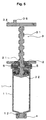
- Fig. 6 is a side sectional view of the kneading device of Fig. 1 with the kneading element and plug fully advanced;
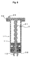
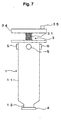
- Figs. 7 and 8 are, respectively, side and side sectional views of a second device according to the invention, incorporating alternative forms of kneading element;
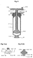
- Figs 9(a) and (b), 10(a) and (b), 11(a) and (b) and 12(a) and (b) are respectively side and sectional views of different forms of kneading elements; and
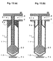
- Figs. 13(a) and (b) are side sectional views of still further forms of device according to the invention.
-
- A kneading device suitable for calcium phosphate-based cement shown in FIGS. 1 and 2 is formed from polypropylene and includes a
cylinder 1, aplug 2, apiston assembly 3, acover member 4, and stopmembers 5. - The
cylinder 1 has a length of about 100 mm and a diameter of about 25 mm and includes a hollowcylindrical body portion 11 of substantially right cylindrical shape and anozzle 12 formed at one end of thecylindrical body portion 11 and adapted for the extrusion of kneaded cement therethrough. Thecylinder 1 can be used to prepare approximately 10 ml of kneaded cement in a single operation. Thenozzle 12 includes a protrusion 121 which constitutes a Luer-Lok structure. - As shown in FIG. 2, the
plug 2 assumes a substantially cylindrical form. It is inserted into thecylinder 1 through the top open end of thecylinder 1 and is fixed in place by means of thestop members 5. An internally-threaded through-hole 21 is formed axially in theplug 2. Reception holes for thestop members 5 are formed in the side wall of theplug 2.Circumferential grooves 22 and 23 are formed in the side wall and the internally-threaded through-hole 21, respectively, of theplug 2, and O-rings 61 and 62 formed of silicone resin are fitted into thegrooves 22 and 23, respectively. - As shown in FIGS. 2 and 3, the
piston assembly 3 includes ashaft 31, akneading element 32, four stirring blades 321A and ahandle 34 including aknob 35. Theshaft 31 assumes the form of an externally-threaded rod. The external threads of theshaft 31 engage theinternal threads 21 of theplug 2, whereby rotation of theshaft 31 causes thepiston assembly 3 to move vertically (axially) within thecylinder 1. - As shown in FIG. 3(a), the
kneading element 32 is located at a distal end of theshaft 31. As shown in FIGS. 3(a) and 3(b), thekneading element 32 includes four stirring blades 321A, which extend radially from the center of thekneading element 32. Each stirring blade 321A has a substantially wedge-like section; i.e., the thickness of the blade decreases towards its radially outer end. - As shown in FIGS. 1 and 2, the
handle 34 assumes the form of a disk, the center of which is attached to the proximal end of theshaft 31. Thehandle 34 has aneccentric knob 35 formed on its upper side which serves for rotating theshaft 31. Thehandle 34 also serves as a finger rest for moving thepiston assembly 3 and theplug 2 toward thenozzle 12 so as to extrude kneaded cement from thecylinder 1. - The
cover member 4 is engaged with the protrusion 121 of thenozzle 12 of thecylinder 1 and is adapted to prevent escape of cement from thecylinder 1 while the cement is being kneaded. Thecover 4 has a protrusion formed at its center so as to prevent kneaded cement from remaining within thecover 4. - Each of the
stop members 5 assumes the form of a pin for fixing theplug 2 in place within thecylinder 1. Eachstop member 5 is inserted through a corresponding through-hole formed in the side wall of thecylinder 1 and into a corresponding reception hole formed in the side wall of theplug 2, thereby fixing theplug 2 within thecylinder 1 at a predetermined position. - The kneading device described above can be easily manufactured and can be stored in a sterile state before use. The kneading device may be used as a disposable tool.
- A method for kneading calcium phosphate-based cement by using the kneading device described above will now be described.
- In order to prevent escape of cement through the
nozzle 12 in the course of kneading, thecover member 4 is attached to thenozzle 12 to thereby block the nozzle. A predetermined amount of cement is then placed into thecylinder 1. Theplug 2 is inserted into the cylinder and is fixed in place by means of thestop members 5. As shown in FIG. 5, theplug 2 and thepiston assembly 3 are engaged beforehand, theshaft 31 of thepiston assembly 3 being screw-engaged with the internally-threaded through-hole 21 of theplug 2, and the kneadingelement 32 being in with theplug 2. - Subsequently, the device containing cement is irradiated with γ rays for sterilization. Since the subsequent kneading operation is performed within the closed device entry of foreign matter or unwanted bacteria into the device can be prevented.
- The
cover member 4 is thereafter removed from thenozzle 12. A Luer-Lok syringe containing a kneading liquid is then connected to thenozzle 12 via a Luer-Lok (not shown) and kneading liquid is injected into the device from the syringe. Subsequently, the syringe is disconnected from the device and thecover member 4 is re-attached to thenozzle 12 to thereby block the nozzle. - The kneading device is gently shaken for, say 10-15 seconds. Then, the
handle 34 is rotated while theknob 35 is grasped in the operator's fingers, so as to move the kneadingelement 32 axially towards thenozzle 12 as shown in FIG. 4. Subsequently, thehandle 34 is rotated counterclockwise so as to move the kneadingelement 32 axially towards theplug 2 as shown in FIG. 5. This back-and-forth operation is repeated, for example 3-10 times to thereby knead the cement and the kneading liquid. - The
cover member 4 and thestop members 5 are then removed from thecylinder 1. Subsequently, as shown in FIG. 6, thehandle 34 is pressed down so as to move thepiston assembly 3 together with theplug 2 axially towards thenozzle 12, thereby extruding kneaded cement from thecylinder 1 through the nozzle. The extruded cement is filled into or applied to a target site, such as a defective portion of bone. - When the pasty kneaded cement is of low viscosity, the cement may be filled into or applied to a target site through a Luer-Lok catheter or a Luer-Lok injection needle attached to the
nozzle 12. - As described above, rotation of the
handle 34 causes rotation of the threadedshaft 31. As a result, the stirring blades 321A formed on the kneadingelement 31 located at the distal end of theshaft 31 rotate and move vertically while stirring the cement and the kneading liquid contained in thecylinder 1. Thus, this kneading operation requires less force and consumes less time than does kneading by use of a mortar. - Further, kneading is performed within a closed space defined by the
cylinder 1, theplug 2, and thecover member 4. After kneading, the device can be used directly for filling kneaded cement into a target site or for applying the cement to a target site, thereby preventing entry of foreign matter or unwanted bacteria into the kneaded cement. Particularly, the O-rings 61 and 62 fitted to sliding surfaces of theplug 2 facilitate rotation of theshaft 31 and sliding of theplug 2 while maintaining closure of the device. - The stirring blades 321A can homogeneously knead the cement, irrespective of the viscosity of the cement. That is, the device can prepare kneaded cement of high viscosity, or low powder-liquid ratio, as well as kneaded cement of low viscosity, or high powder-liquid ratio. Kneaded cement of high viscosity features high formability and high strength. Kneaded cement of low viscosity can be filled into or applied to a target site by means of a fine injection needle.
- Kneaded cements obtained by use of the kneading device were subjected to evaluation tests as follows.
- Cement and a kneading liquid were kneaded in the proportions shown in Table 1 according to the method described above, thereby obtaining kneaded cements of Examples 1 and 2. The kneaded cement of Example 1 has a high viscosity and exhibits the consistency of clay. The kneaded cement of Example 2 has a low viscosity and can be extruded through an injection needle of gauge 18.
- The kneaded cements of Comparative Examples 1 and 2 were obtained by kneading in a mortar the cement and the kneading liquid at powder-liquid ratio shown in Table 1.
Cement Kneading liquid Powder-liquid weight ratio Wet compressive strength Example 1 20 g 4.6 g 0.23 598 kg/cm2 Example 2 20 g 6.0 g 0.30 465 kg/cm2 Comparative Example 1 20 g 4.6 g 0.23 613 kg/cm2 Comparative Example 2 20 g 6.0 g 0.30 421 kg/cm2 Cement: equimolar powder mixture of calcium hydrogenphosphate and tetracalcium phosphate
Kneading liquid: pure water - In order to examine the homogeneity of these kneaded cements, the kneading liquid contained a red pigment. The homogeneity of the kneaded cements was determined through visual observation for irregular color. The kneaded cements of Examples 1 and 2 exhibited a homogeneously kneaded state.
- The kneaded cements of Examples 1 and 2 and of Comparative Examples 1 and 2 were tested for wet compressive strength according to the decay rate test method described in JIS T 6602. Specifically, each of the kneaded cements was filled into a die having a depth of 11 mm and a diameter of 6 mm and the cement was allowed to cure at a temperature of 37°C and a relative humidity of 100% for 1 hour. The cured cement was then removed from the die and immersed in pseudo body fluid [aqueous solution containing Na+ (142.0 mmol), K+ (5.0 mmol), Ca2+ (2.5 mmol), Mg2+ (1.5 mmol), HCO3 -(4.2 mmol), Cl- (148.0 mmol), HPO4 2- (1.0 mmol), SO4 2- (0.5 mmol), TRIS buffer (33.3 mmol), and hydrochloric acid (30 mM)] having a temperature of 37°C for 24 hours. Subsequently, the cement was tested for wet compressive strength by use of a compressive strength test machine (product of Instron Corp.). The test results are shown in Table 1.
- As seen from Table 1, the cements of Examples 1 and 2, which were prepared by means of the kneading device of the present invention, exhibit wet compressive strength values substantially equivalent to these exhibited by the kneaded cements of Comparative Examples 1 and 2, which were prepared by use of a mortar. That is, the method of the present invention yields kneaded cement in a kneading operation easier than that of the conventional method. The cement cures to hardness equivalent to that associated with kneaded cement obtained by the conventional method.
- In order to examine the relationship between the form of the
stirring blades 321 and the degree of mixing, there were assembled kneading devices A, B, C, D and E having stirring blades 321A (FIG. 3), 321B (FIG. 9), 321C (FIG. 10), 321D (FIG. 11) and 321E (FIG. 12). These devices A, B, C, D and E were tested for kneading operability and the degree of mixing. - The device A having the stirring blades 321A shown in FIG. 3 produced good kneaded cement when the
internal threads 21 and theshaft 31 had a thread pitch of about 10 mm. Time required for kneading was about 2 minutes. The percentage of residual kneaded cement after extrusion was not greater than 10%. - The device B having the stirring blades 321B shown in FIG. 9 produced good kneaded cement when the thread pitch was about 2.5 mm. Accordingly, time required for kneading was longer than that required in the case of the stirring blade 321A. Similarly, the device C having the stirring blades 321C shown in FIG. 10 produced good kneaded cement.
- The devices D and E having the stirring blades 321D and 321E of FIGS. 11 and 12, respectively, had the disadvantage that cement powder was caught in the gap between the stirring blades 321D and between the stirring blades 321E, resulting in a tendency toward lower homogeneity of kneaded cement as compared to the devices A, B, and C.
- The present invention has been described with reference to specific embodiments, but may be embodied in many other specific forms according to objectives or applications without departing from the spirit or scope of the invention. For example, the cover member for the
nozzle 12 may assume a plug-type form as shown in FIGS. 7 and 8. Alternatively, the cover member for thenozzle 12 may assume the form of a protrusion 4a as shown in FIG. 13(a), which is integrally formed with thecylinder 1 and can be broken off. A device having the protrusion 4a, which serves as a cover member for the nozzle, prevents escape of cement or kneaded cement from the cylinder through the nozzle unless the protrusion is broken off. Also, the device having the protrusion 4a permits immediate observation as to whether it has been used. - The form of the stirring blades can be modified according to application. For example, the stirring blades may be arranged to incline with respect to the axis of the kneading element. Alternatively, the stirring blades may be arranged non-symmetrically with respect to the axis of the kneading element.
- The above embodiments have been described using a pin-type stop member. However, the device is not limited thereto. The stop member may assume the form of any other anchoring means. For example, as shown in FIG. 13(a), an upper portion of the
cylinder 1 may be formed with an elastic portion 5a serving as a stop member. A protrusion 51a formed on the elastic portion 5a engages theplug 2 to thereby locate the plug in position. Alternatively, as shown in FIG. 13(b), a portion of theplug 2 may be formed into an elastic portion 5b serving as a stop member. A protrusion 51b formed on the elastic portion 5b is engaged by thecylinder 1 to thereby locate the plug in position. Since the elastic portions 5a and 5b are a portion of thecylinder 1 and theplug 2, respectively, such stop members cannot become lost or misplaced. - By use of the kneading device of the present invention and the method for preparing kneaded calcium phosphate-based cement using it, calcium phosphate-based cement can be quickly prepared through kneading and filled into or applied to a target site. Also, entry of foreign matter or unwanted bacteria into the device in the course of kneading can be prevented. Further, homogeneously kneaded cement can be obtained irrespective of viscosity of the cement.
- As a result of the kneading element including the stirring blades described above, kneading can be performed more homogeneously. Use of the O-rings results in the kneading operation being facilitated, and entry of foreign matter or unwanted bacteria into the kneader in the course of kneading can be prevented more effectively.
Claims (7)
- A kneading device suitable for preparing calcium phosphate-based cement, said device comprising: a cylinder (1), which includes a hollow cylindrical body portion (11) and a nozzle (12) formed at the distal end of the cylindrical body portion; a plug (2) including an axial through-hole (21), slidably disposed within the proximal end of the cylindrical body portion; a piston assembly (3) which includes a shaft (31) extending through the through-hole of the plug for axial and rotatable movement, a kneading element (32) at the distal end of the shaft within the cylindrical body portion and a handle (34) formed at the proximal end of the shaft external of the cylindrical body portion; a cover member (4) attached to and forming a closure for the nozzle; and a stop member (5) for locating the plug in position at the proximal end of the cylindrical body portion.
- A kneading device according to claim 1, wherein the kneading element (32) incorporates a stirring blade (321A,321B,321C) disposed along its circumferentially peripheral edges.
- A kneading device according to claim 1 or claim 2, wherein the outer surface of the plug (2) has a circumferential groove (22) formed therein and wherein the device includes also an O-ring (61) of an elastomeric material located within the groove thereby to form a seal between the outer surface of the plug and the interior of the hollow cylindrical body portion.
- A kneading device according to any one of claims 1 to 3, wherein the through-hole (21) of the plug (2) has a circumferential groove (23) formed therein and wherein the device includes also an O-ring (62) of an elastomeric material located within the groove thereby to form a seal between the through-hole of the plug and the shaft of the piston assembly.
- A kneading device according to any one of claims 1 to 4, wherein the shaft is threaded through said through-hole of said plug.
- A kneading device according to claim 5, wherein the thread has a pitch of 5-25mm.
- A method for preparing calcium phosphate-based cement, the method comprising the steps of:introducing calcium phosphate-based cement and a kneading liquid into the space defined by the cylinder (1) and the plug (2) of a kneading device according to any one of claims 1 to 6;rotating and vertically moving the piston assembly (3) within the cylinder so as to thereby knead the calcium phosphate-based cement and the kneading liquid into kneaded cement, moving the piston assembly such that the kneading element (32) comes into contact with the plug, and detaching the cover member (4) and the stop member (5); andmoving the piston assembly and plug towards the nozzle (12) so as thereby to extrude the kneaded cement from the cylinder through the nozzle.
Applications Claiming Priority (2)
| Application Number | Priority Date | Filing Date | Title |
|---|---|---|---|
| JP28730299A JP4159202B2 (en) | 1998-12-21 | 1999-10-07 | Calcium phosphate cement kneading apparatus and method for preparing calcium phosphate cement kneaded material |
| JP28730299 | 1999-10-07 |
Publications (1)
| Publication Number | Publication Date |
|---|---|
| EP1090609A1 true EP1090609A1 (en) | 2001-04-11 |
Family
ID=17715623
Family Applications (1)
| Application Number | Title | Priority Date | Filing Date |
|---|---|---|---|
| EP00305155A Withdrawn EP1090609A1 (en) | 1999-10-07 | 2000-06-19 | Device and method for preparing calcium phosphate-based cement |
Country Status (2)
| Country | Link |
|---|---|
| US (1) | US6550957B2 (en) |
| EP (1) | EP1090609A1 (en) |
Cited By (2)
| Publication number | Priority date | Publication date | Assignee | Title |
|---|---|---|---|---|
| WO2005048886A3 (en) * | 2003-11-18 | 2005-07-28 | Scimed Life Systems Inc | Apparatus for mixing and dispensing a multi-component bone cement |
| WO2006118884A3 (en) * | 2005-04-29 | 2007-03-01 | Wyeth Corp | Drug delivery devices and related components, systems and methods |
Families Citing this family (42)
| Publication number | Priority date | Publication date | Assignee | Title |
|---|---|---|---|---|
| SE524714C2 (en) * | 2002-06-28 | 2004-09-21 | Asept Medical Ab | Bone cement processor and applicator |
| GB0218310D0 (en) * | 2002-08-07 | 2002-09-11 | Depuy Int Ltd | An instrument for preparing a bone cement material |
| US7153454B2 (en) * | 2003-01-21 | 2006-12-26 | University Of Southern California | Multi-nozzle assembly for extrusion of wall |
| ES2545328T3 (en) | 2003-03-14 | 2015-09-10 | Depuy Spine, Inc. | Bone cement hydraulic injection device in percutaneous vertebroplasty |
| US7014640B2 (en) * | 2003-03-28 | 2006-03-21 | Depuy Products, Inc. | Bone graft delivery device and method of use |
| US8066713B2 (en) | 2003-03-31 | 2011-11-29 | Depuy Spine, Inc. | Remotely-activated vertebroplasty injection device |
| US20040267272A1 (en) * | 2003-05-12 | 2004-12-30 | Henniges Bruce D | Bone cement mixing and delivery system |
| WO2006011152A2 (en) | 2004-06-17 | 2006-02-02 | Disc-O-Tech Medical Technologies, Ltd. | Methods for treating bone and other tissue |
| US8415407B2 (en) | 2004-03-21 | 2013-04-09 | Depuy Spine, Inc. | Methods, materials, and apparatus for treating bone and other tissue |
| US7736049B2 (en) * | 2003-08-21 | 2010-06-15 | Medmix Systems Ag | Device and method for the storage mixing and dispensing components |
| US20050060100A1 (en) * | 2003-09-15 | 2005-03-17 | Becton Dickinson And Company | Computer software and algorithms for systems biologically linked to cellular phenotype |
| WO2005030034A2 (en) | 2003-09-26 | 2005-04-07 | Depuy Spine, Inc. | Device for delivering viscous material |
| US20050105384A1 (en) * | 2003-11-18 | 2005-05-19 | Scimed Life Systems, Inc. | Apparatus for mixing and dispensing a multi-component bone cement |
| US20080319445A9 (en) * | 2004-08-17 | 2008-12-25 | Scimed Life Systems, Inc. | Apparatus and methods for delivering compounds into vertebrae for vertebroplasty |
| US8038682B2 (en) * | 2004-08-17 | 2011-10-18 | Boston Scientific Scimed, Inc. | Apparatus and methods for delivering compounds into vertebrae for vertebroplasty |
| US8727605B2 (en) * | 2005-01-21 | 2014-05-20 | Medic Tools Ag | One-way mixer homogenizer, extractor, fractioner or slurry producer |
| US8029183B2 (en) * | 2005-02-23 | 2011-10-04 | Biomet Manufacturing Corp. | Apparatus for mixing bone cement |
| US9381024B2 (en) | 2005-07-31 | 2016-07-05 | DePuy Synthes Products, Inc. | Marked tools |
| US9918767B2 (en) | 2005-08-01 | 2018-03-20 | DePuy Synthes Products, Inc. | Temperature control system |
| US8360629B2 (en) | 2005-11-22 | 2013-01-29 | Depuy Spine, Inc. | Mixing apparatus having central and planetary mixing elements |
| CN101415483A (en) * | 2006-02-10 | 2009-04-22 | 陶氏环球技术公司 | Retractable pin mixing sample forming device |
| EP2059196A2 (en) * | 2006-09-07 | 2009-05-20 | Wyeth | Bone cement mixing systems and related methods |
| CA2663447A1 (en) | 2006-09-14 | 2008-03-20 | Depuy Spine, Inc. | Polymeric bone cement and methods of use thereof |
| EP2091818B1 (en) | 2006-10-19 | 2016-06-08 | DePuy Spine, Inc. | Fluid delivery system and related method |
| US7905654B1 (en) * | 2006-11-13 | 2011-03-15 | Luis Cordero | Hand held manually operated mixer |
| DE102008030623A1 (en) * | 2008-01-03 | 2009-07-09 | Umsonst-Kübler, Petra | Device for mixing a mass |
| US8167835B2 (en) * | 2008-02-28 | 2012-05-01 | Medmix Systems Ag | Single chamber device for drawing in and dispensing components |
| AU2009296318B2 (en) | 2008-09-29 | 2014-09-18 | Lidds Ab | Injector device |
| USD635248S1 (en) | 2009-04-03 | 2011-03-29 | Ebi, Llc | Bone cement dispenser |
| EP2413992B1 (en) | 2009-04-03 | 2019-07-03 | Zimmer Biomet Spine, Inc. | Apparatus for delivering bone cement |
| DE102010052323A1 (en) | 2010-11-25 | 2012-05-31 | Heraeus Medical Gmbh | Cartridge with lockable delivery piston |
| CA143779S (en) * | 2011-08-19 | 2012-07-26 | Sulzer Mixpac Ag | Mixer |
| US8833606B2 (en) | 2012-01-03 | 2014-09-16 | Howmedica Osteonics Corporation | Device and method for mixing and applying biomaterials |
| US8845578B2 (en) * | 2013-02-28 | 2014-09-30 | Medtronic Xomed, Inc. | Biomaterial delivery device |
| US8920364B2 (en) | 2013-02-28 | 2014-12-30 | Medtronic Xomed, Inc. | Biomaterial delivery device |
| CA153529S (en) * | 2013-05-29 | 2014-07-31 | Sulzer Mixpac Ag | Dynamic mixer |
| ES2759858T3 (en) * | 2014-08-29 | 2020-05-12 | Milton Roy Europe | Disassembly system of the sealing of a ball joint |
| CN104482191B (en) * | 2014-12-25 | 2018-02-06 | 成都中车电机有限公司 | A kind of agitating device applied to installing locomotive gear cases |
| US10758287B2 (en) | 2018-09-13 | 2020-09-01 | Warsaw Orthopedic, Inc. | Bone material mixing and dispensing devices and methods |
| DE102020134316A1 (en) * | 2020-12-18 | 2022-06-23 | Kulzer Gmbh | Rotor shaft with worm thread for a dynamic mixer for mixing low to high viscosity components |
| US11241330B1 (en) | 2021-04-02 | 2022-02-08 | Brixton Biosciences, Inc. | Apparatus for creation of injectable slurry |
| US11737802B1 (en) * | 2022-07-25 | 2023-08-29 | Zavation Medical Products, Llc | Bone cement mixer |
Citations (13)
| Publication number | Priority date | Publication date | Assignee | Title |
|---|---|---|---|---|
| US2825134A (en) * | 1956-01-09 | 1958-03-04 | Paul L Hicks | Device for use in making impressions from dental impression material |
| US3417971A (en) * | 1967-02-23 | 1968-12-24 | Robert J. Blank | Mixing and ejection tool |
| US3724077A (en) * | 1971-11-26 | 1973-04-03 | Unitek Corp | Mixing syringe |
| WO1986006618A1 (en) * | 1985-05-14 | 1986-11-20 | Labor Für Experimentelle Chirurgie | Method and apparatus for preparaing a self-curing two component powder/liquid cement |
| DE3640279A1 (en) * | 1985-12-23 | 1987-06-25 | Mit Ab | DEVICE FOR MIXING BONE CEMENT IN A VACUUM |
| WO1990013264A1 (en) * | 1989-05-03 | 1990-11-15 | Surgitec Ab | Device for preparing bone cement |
| EP0445951A2 (en) * | 1990-03-09 | 1991-09-11 | Howmedica Inc. | Surgical adhesives mixing and dispensing implement |
| EP0603871A2 (en) * | 1992-12-23 | 1994-06-29 | Volkmar Dr. Jansson | Process and apparatus for mixing and applying bone cement |
| EP0692229A1 (en) * | 1994-07-16 | 1996-01-17 | MERCK PATENT GmbH | Mixing and dispensing device for bone cement |
| DE19532015A1 (en) * | 1995-08-31 | 1997-03-06 | Alfred Von Schuckmann | Device for mixing and dispensing multi-component products |
| WO1997021485A1 (en) * | 1995-12-09 | 1997-06-19 | Depuy International Limited | Mixing bone cement |
| GB2338428A (en) * | 1998-06-19 | 1999-12-22 | David Grant | A syringe with an agitator whose shaft passes through a slidable dispensing plunger |
| EP1090610A2 (en) * | 1999-10-06 | 2001-04-11 | Ngk Spark Plug Co., Ltd | Assisting-tool for extruding a chemical agent, kneader for preparing and extruding a chemical agent, and methods for using the same |
Family Cites Families (18)
| Publication number | Priority date | Publication date | Assignee | Title |
|---|---|---|---|---|
| US3140078A (en) | 1961-06-15 | 1964-07-07 | Adhesive Eng Co | Mixing and dispensing device |
| US3188057A (en) | 1962-03-12 | 1965-06-08 | Pyles Ind Inc | Apparatus for mixing and dispensing multi-component materials |
| US3475010A (en) | 1968-04-24 | 1969-10-28 | Prod Res & Chem Corp | Dispensing cartridge for intermixing separate ingredients |
| NL140052B (en) | 1970-02-09 | 1973-10-15 | Vries Robert De | DISPENSER FOR ICE CREAM |
| US3858853A (en) | 1973-05-25 | 1975-01-07 | Paul Gilger Rausch | Container with mixer and method of use |
| US4371094A (en) | 1980-07-31 | 1983-02-01 | Products Research & Chemical Corporation | Barrier two part pairing and dispensing cartridge |
| US4469153A (en) | 1981-05-15 | 1984-09-04 | Kidde, Inc. | Apparatus for mixing and dispensing liquids |
| FR2533495B2 (en) | 1981-12-18 | 1986-05-30 | Morel Atel Electromec | CARTRIDGE FOR INJECTING A SEMI-PASTA PRODUCT |
| AT382090B (en) | 1985-03-21 | 1987-01-12 | Kreuziger Wolf Dieter | MIXING DEVICE AND METHOD FOR THEIR OPERATION |
| US4676655A (en) | 1985-11-18 | 1987-06-30 | Isidore Handler | Plunger type cartridge mixer for fluent materials |
| DE3708803A1 (en) | 1987-03-18 | 1988-09-29 | Fischbach A Kunststoff Kg | MIXING DEVICE FOR PASTOESE MULTI-COMPONENT DIMENSIONS |
| DE3723309A1 (en) | 1987-07-15 | 1989-01-26 | Fischbach A Kunststoff Kg | MIXING DEVICE |
| US4863072A (en) | 1987-08-18 | 1989-09-05 | Robert Perler | Single hand operable dental composite package |
| JP3123214B2 (en) | 1992-05-20 | 2001-01-09 | 三菱マテリアル株式会社 | Container and filling device for kneading calcium phosphate cement |
| JP3371688B2 (en) | 1996-06-11 | 2003-01-27 | 三菱マテリアル株式会社 | Biological cement injector |
| CA2274787C (en) | 1996-12-13 | 2009-01-27 | Norian Corporation | Preparation, storage and administration of cements |
| US5842786A (en) | 1997-03-07 | 1998-12-01 | Solomon; Alan | Method and device for mixing medical compositions |
| JP3414195B2 (en) | 1997-05-20 | 2003-06-09 | 三菱マテリアル株式会社 | Medical cement kneading injector |
-
2000
- 2000-06-19 EP EP00305155A patent/EP1090609A1/en not_active Withdrawn
-
2002
- 2002-02-22 US US10/079,568 patent/US6550957B2/en not_active Expired - Lifetime
Patent Citations (13)
| Publication number | Priority date | Publication date | Assignee | Title |
|---|---|---|---|---|
| US2825134A (en) * | 1956-01-09 | 1958-03-04 | Paul L Hicks | Device for use in making impressions from dental impression material |
| US3417971A (en) * | 1967-02-23 | 1968-12-24 | Robert J. Blank | Mixing and ejection tool |
| US3724077A (en) * | 1971-11-26 | 1973-04-03 | Unitek Corp | Mixing syringe |
| WO1986006618A1 (en) * | 1985-05-14 | 1986-11-20 | Labor Für Experimentelle Chirurgie | Method and apparatus for preparaing a self-curing two component powder/liquid cement |
| DE3640279A1 (en) * | 1985-12-23 | 1987-06-25 | Mit Ab | DEVICE FOR MIXING BONE CEMENT IN A VACUUM |
| WO1990013264A1 (en) * | 1989-05-03 | 1990-11-15 | Surgitec Ab | Device for preparing bone cement |
| EP0445951A2 (en) * | 1990-03-09 | 1991-09-11 | Howmedica Inc. | Surgical adhesives mixing and dispensing implement |
| EP0603871A2 (en) * | 1992-12-23 | 1994-06-29 | Volkmar Dr. Jansson | Process and apparatus for mixing and applying bone cement |
| EP0692229A1 (en) * | 1994-07-16 | 1996-01-17 | MERCK PATENT GmbH | Mixing and dispensing device for bone cement |
| DE19532015A1 (en) * | 1995-08-31 | 1997-03-06 | Alfred Von Schuckmann | Device for mixing and dispensing multi-component products |
| WO1997021485A1 (en) * | 1995-12-09 | 1997-06-19 | Depuy International Limited | Mixing bone cement |
| GB2338428A (en) * | 1998-06-19 | 1999-12-22 | David Grant | A syringe with an agitator whose shaft passes through a slidable dispensing plunger |
| EP1090610A2 (en) * | 1999-10-06 | 2001-04-11 | Ngk Spark Plug Co., Ltd | Assisting-tool for extruding a chemical agent, kneader for preparing and extruding a chemical agent, and methods for using the same |
Cited By (2)
| Publication number | Priority date | Publication date | Assignee | Title |
|---|---|---|---|---|
| WO2005048886A3 (en) * | 2003-11-18 | 2005-07-28 | Scimed Life Systems Inc | Apparatus for mixing and dispensing a multi-component bone cement |
| WO2006118884A3 (en) * | 2005-04-29 | 2007-03-01 | Wyeth Corp | Drug delivery devices and related components, systems and methods |
Also Published As
| Publication number | Publication date |
|---|---|
| US20020118596A1 (en) | 2002-08-29 |
| US6550957B2 (en) | 2003-04-22 |
Similar Documents
| Publication | Publication Date | Title |
|---|---|---|
| US6367962B1 (en) | Device and method for preparing calcium phosphate-based bone cement | |
| US6550957B2 (en) | Device and method for preparing calcium phosphate-based cement | |
| EP1433446B1 (en) | Assisting-tool for extruding a chemical agent, kneader for preparing and extruding a chemical agent, and methods for using the same | |
| US12172142B2 (en) | Bone cement mixing and delivery system with reduced fume exposure | |
| CA2581766C (en) | Curable material mixing and delivery device | |
| US6676663B2 (en) | Applicator device for controllably injecting a surgical cement into bones | |
| EP2436342B1 (en) | Device for the application of bone substitute material | |
| WO2005096970A2 (en) | Methods and devices for cavity creation in mammalian bone tissue | |
| US20140269147A1 (en) | Bone cement mixing and delivery system with reduced fume exposure | |
| JP2001218774A (en) | Kneading device for calcium phosphate cement and method for preparing calcium phosphate cement using the same | |
| US10098682B2 (en) | High pressure remote delivery system for cement and methods of use | |
| KR20120082885A (en) | Bone cement containing bone marrow | |
| JP6936005B2 (en) | Syringe and treatment set | |
| EP3212099B1 (en) | Device for applying bone replacement pastes | |
| JP4185254B2 (en) | Kneading container, injector and kneading device | |
| EP3831344A1 (en) | Seal for application of bone cement | |
| JP2009095608A (en) | Medical paste injection kneader and medical paste injection kneader | |
| CN121400954A (en) | Device for mixing and injecting compositions, especially bone cement. | |
| JP2000350737A (en) | Kneading device for calcium phosphate cement and method for preparing calcium phosphate cement |
Legal Events
| Date | Code | Title | Description |
|---|---|---|---|
| PUAI | Public reference made under article 153(3) epc to a published international application that has entered the european phase |
Free format text: ORIGINAL CODE: 0009012 |
|
| AK | Designated contracting states |
Kind code of ref document: A1 Designated state(s): DE FR GB |
|
| AX | Request for extension of the european patent |
Free format text: AL;LT;LV;MK;RO;SI |
|
| 17P | Request for examination filed |
Effective date: 20011005 |
|
| AKX | Designation fees paid |
Free format text: DE FR GB |
|
| 17Q | First examination report despatched |
Effective date: 20030915 |
|
| STAA | Information on the status of an ep patent application or granted ep patent |
Free format text: STATUS: THE APPLICATION IS DEEMED TO BE WITHDRAWN |
|
| 18D | Application deemed to be withdrawn |
Effective date: 20040326 |