EP1090586A2 - Methods and apparatus for cardiac imaging with conventional computed tomography - Google Patents
Methods and apparatus for cardiac imaging with conventional computed tomography Download PDFInfo
- Publication number
- EP1090586A2 EP1090586A2 EP00308616A EP00308616A EP1090586A2 EP 1090586 A2 EP1090586 A2 EP 1090586A2 EP 00308616 A EP00308616 A EP 00308616A EP 00308616 A EP00308616 A EP 00308616A EP 1090586 A2 EP1090586 A2 EP 1090586A2
- Authority
- EP
- European Patent Office
- Prior art keywords
- patient
- heart
- segments
- accordance
- scanning
- Prior art date
- Legal status (The legal status is an assumption and is not a legal conclusion. Google has not performed a legal analysis and makes no representation as to the accuracy of the status listed.)
- Withdrawn
Links
Images


Classifications
-
- A—HUMAN NECESSITIES
- A61—MEDICAL OR VETERINARY SCIENCE; HYGIENE
- A61B—DIAGNOSIS; SURGERY; IDENTIFICATION
- A61B6/00—Apparatus or devices for radiation diagnosis; Apparatus or devices for radiation diagnosis combined with radiation therapy equipment
- A61B6/54—Control of apparatus or devices for radiation diagnosis
- A61B6/541—Control of apparatus or devices for radiation diagnosis involving acquisition triggered by a physiological signal
-
- A—HUMAN NECESSITIES
- A61—MEDICAL OR VETERINARY SCIENCE; HYGIENE
- A61B—DIAGNOSIS; SURGERY; IDENTIFICATION
- A61B6/00—Apparatus or devices for radiation diagnosis; Apparatus or devices for radiation diagnosis combined with radiation therapy equipment
- A61B6/02—Arrangements for diagnosis sequentially in different planes; Stereoscopic radiation diagnosis
- A61B6/03—Computed tomography [CT]
- A61B6/032—Transmission computed tomography [CT]
-
- A—HUMAN NECESSITIES
- A61—MEDICAL OR VETERINARY SCIENCE; HYGIENE
- A61B—DIAGNOSIS; SURGERY; IDENTIFICATION
- A61B6/00—Apparatus or devices for radiation diagnosis; Apparatus or devices for radiation diagnosis combined with radiation therapy equipment
- A61B6/50—Apparatus or devices for radiation diagnosis; Apparatus or devices for radiation diagnosis combined with radiation therapy equipment specially adapted for specific body parts; specially adapted for specific clinical applications
- A61B6/503—Apparatus or devices for radiation diagnosis; Apparatus or devices for radiation diagnosis combined with radiation therapy equipment specially adapted for specific body parts; specially adapted for specific clinical applications for diagnosis of the heart
-
- A—HUMAN NECESSITIES
- A61—MEDICAL OR VETERINARY SCIENCE; HYGIENE
- A61B—DIAGNOSIS; SURGERY; IDENTIFICATION
- A61B6/00—Apparatus or devices for radiation diagnosis; Apparatus or devices for radiation diagnosis combined with radiation therapy equipment
- A61B6/02—Arrangements for diagnosis sequentially in different planes; Stereoscopic radiation diagnosis
- A61B6/027—Arrangements for diagnosis sequentially in different planes; Stereoscopic radiation diagnosis characterised by the use of a particular data acquisition trajectory, e.g. helical or spiral
Definitions
- This invention relates generally to methods and apparatus for cardiac CT imaging, and more particularly to methods and apparatus for reducing induced motion artifacts in cardiac CT imaging.
- an x-ray source projects a fan-shaped beam which is collimated to lie within an X-Y plane of a Cartesian coordinate system and generally referred to as the "imaging plane".
- the x-ray beam passes through the object being imaged, such as a patient.
- the beam after being attenuated by the object, impinges-upon an array of radiation detectors.
- the intensity of the attenuated beam radiation received at the detector array is dependent upon the attenuation of the x-ray beam by the object.
- Each detector element of the array produces a separate electrical signal that is a measurement of the beam attenuation at the detector location.
- the attenuation measurements from all the detectors are acquired separately to produce a transmission profile.
- the x-ray source and the detector array are rotated with a gantry within the imaging plane and around the object to be imaged so that the angle at which the x-ray beam intersects the object constantly changes.
- a group of x-ray attenuation measurements, i.e., projection data, from the detector array at one gantry angle is referred to as a "view”.
- a "scan" of the object comprises a set of views made at different gantry angles, or view angles, during one revolution of the x-ray source and detector.
- the projection data is processed to construct an image that corresponds to a two dimensional slice taken through the object.
- CT numbers integers called "CT numbers” or “Hounsfield units”, which are used to control the brightness of a corresponding pixel on a cathode ray tube display.
- the rotating gantry rotates at a rate no greater than 2.0 rotations per second, or equivalently, 0.5 seconds per rotation.
- a typical period for a cardiac cycle is slightly less than one second.
- Motion-induced image artifacts result and are a major problem in cardiac CT imaging.
- an entire scan is performed in a fraction of cardiac cycle with an electron beam CT (EBCT) imaging device.
- EBCT electron beam CT
- x-ray emissions generated by a scanning electron beam are used for imaging.
- the present invention thus provides methods and apparatus for reducing motion-induced artifacts in CT imaging equipment, including those with a conventional rotating gantry, radiation source, and radiation detector array.
- a method for imaging a heart with a scanning computed tomography (CT) imaging system in which a cardiac cycle of a patient is measured; the patient's heart is scanned with the scanning CT imaging system, at an angular rate asynchronous to the measured cardiac cycle to obtain image data; and an image of the patient's heart is assembled from chronologically discontinuous segments of the image data.
- the assembled image is representative of a selected portion of the cardiac cycle, for example, a relatively quiescent portion.
- the above-described embodiment provides greatly improved temporal resolution, because a complete data set can be formed from chronologically discontinuous segments of image data that are each obtained during a very short period of time and at equivalent phases of the patient's cardiac cycle.
- No special gantry, radiation source, or detector array is required for the CT scanning equipment, yet temporal resolutions comparable to those obtainable with EBCT imaging devices is attainable.
- the resulting images are useful in medical applications requiring high temporal resolution images, for example, calcification scoring, which requires a high-resolution image of a relatively still heart.
- Figure 1 is a pictorial view of a CT imaging system.
- Figure 2 is a block schematic diagram of the system illustrated in Figure 1.
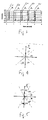
- Figure 3 is a graph illustrative of segments of image data obtained in one embodiment of the present invention, relative to phases of a cardiac cycle of a patient.
- Figure 4 is a chart illustrative of chronologically discontinuous segments of image data obtained sequentially one embodiment of the invention.
- Figure 5 is a chart illustrative of segments of shuffled, chronologically discontinuous image data obtained in another embodiment of the invention.
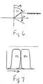
- Figure 6 is a chart illustrative of overlapping of image data segments.
- Figure 7 is a chart showing blending of adjacent, overlapping image data segments.
- Figure 8 is a graph showing a weighted scan of 180° plus one fan angle divided into four equal segments for scanning, so that the first and last segments have substantially better resolution than the middle two segments.
- Figure 9 is a graph showing a weighted scan of 180° plus one fan angle divided into unequal segments for scanning, to equalize temporal resolution of the segments after weighting is applied.
- a computed tomograph (CT) imaging system 10 is shown as including a gantry 12 representative of a "third generation" CT scanner.
- Gantry 12 has an x-ray source 14 that projects a beam of x-rays 16 toward a detector array 18 on the opposite side of gantry 12.
- Detector array 18 is formed by detector elements 20 which together sense the projected x-rays that pass through an object 22, for example a medical patient.
- Detector array 18 may be fabricated in a single slice or multi-slice configuration.
- Each detector element 20 produces an electrical signal that represents the intensity of an impinging x-ray beam and hence the attenuation of the beam as it passes through patient 22.
- gantry 12 and the components mounted thereon rotate about a center of rotation 24.
- Control mechanism 26 includes an x-ray controller 28 that provides power and timing signals to x-ray source 14 and a gantry motor controller 30 that controls the rotational speed and position of gantry 12.
- a data acquisition system (DAS) 32 in control mechanism 26 samples analog data from detector elements 20 and converts the data to digital signals for subsequent processing.
- An image reconstructor 34 receives sampled and digitized x-ray data from DAS 32 and performs high speed image reconstruction. The reconstructed image is applied as an input to a computer 36 which stores the image in a mass storage device 38.
- DAS data acquisition system
- Computer 36 also receives commands and scanning parameters from an operator via console 40 that has a keyboard.
- An associated cathode ray tube display 42 allows the operator to observe the reconstructed image and other data from computer 36.
- the operator supplied commands and parameters are used by computer 36 to provide control signals and information to DAS 32, x-ray controller 28 and gantry motor controller 30.
- computer 36 operates a table motor controller 44 which controls a motorized table 46 to position patient 22 in gantry 12. Particularly, table 46 moves portions of patient 22 through gantry opening 48 along an axis of rotation of gantry 12, i.e., along a z-axis.
- CT imaging system 10 provides significantly improved temporal resolution by scanning the heart of patient 22 at an angular rate asynchronous to a measured cardiac cycle to obtain imaging data. An image of the heart of patient 22 at a selected portion of the cardiac cycle is then reassembled from chronologically discontinuous segments of image data.
- An EKG machine 50 is used to obtain an EKG recording of patient 22 immediately before scanning with imaging system 10. It is assumed that an EKG obtained at this time, such as that shown in Figure 3, is adequately representative of a heart rate of patient 22 during a scan. Peaks R, which are nearly one second apart, are preceded by a relatively quiescent period 52 of the cardiac cycle of patient 22. Because the heart is relatively still during this portion of the cycle, this is the most advantageous portion for providing images with a minimum of motion-induced artifacts. Quiescent period 52 is also selected for imaging in at least one known diagnostic test in which cardiac calcification deposits are scored.
- Quiescent period 52 is too short to provide a satisfactory image of the heart when gantry 12 completes a full 360° rotation every 0.5 seconds. Therefore, image data is collected, one during each successive quiescent period 52 during a plurality of gantry rotations, each time at gantry positions providing segments having different view angles.
- image data from segments that, in total, correspond to a scan of 180° plus a fan angle of data is accumulated over five cardiac cycles.
- a fan angle is defined as an angle of fan-shaped radiation beam 16 intercepted by detector array 18.
- a total amount of image data corresponding to 180° plus one fan angle is collected in 0.3 seconds.
- Five segments totaling this amount of image data are collected during quiescent period 52. Each segment represents data collected in a 60 millisecond window, and each segment is representative of only a portion of a total scan of 180° plus one fan angle. However, the five segments are of adjacent angular ranges, so that, when assembled, a total scan of 180° plus one fan angle is produced.
- Each 60 millisecond window occurs during a different rotational cycle of gantry 12, but at a corresponding portion of a cardiac cycle.
- Different numbers of image segments can be collected, depending upon the rate of rotation of gantry 12 and a cardiac cycle of patient 22.
- Cardiac cycle time of the heart of patient 22 is measured, and a rotation rate of gantry 12 is set that is asynchronous with the measured cardiac cycle time.
- An asynchronous gantry rotation rate is selected to ensure that image data obtained during multiple segments represent essentially non-overlapping or only slightly overlapping angular portions of a total assembled scan. For example, if a measured heart rate is 60 beats per minute (bpm), a rate of 1.0 rotations per second would be unsatisfactory, because gantry 12 would be at the same angle during identical phases of the cardiac cycle.
- data acquisition is accomplished in an axial mode.
- Table 46 on which patient 22 rests, remains stationary during multiple gantry 12 rotations, for example, five rotations, during which a set of chronologically discontinuous image data to be assembled is collected. After the image data is collected, table 46 is indexed or stepped in a z-axis direction to another location if additional slices of data are to be collected.
- data acquisition is accomplished in a helical scan mode, so that table 46 advances during scanning along a z-axis.
- a helical pitch is selected in accordance with a number of segments desired for image reconstruction and a selected z-axis location for all segments.
- CT scanner 10 operates in four-slice mode, and eight segments are desired to form a complete data set.
- a helical pitch of 0.5:1 is used so that the same z-axis slice location is viewed eight times during data acquisition.
- helical pitch is optimized for sampling continuity.
- scanner 10 operates in four-slice mode, and helical pitch of 5/6:1 is used to ensure that each segment starts at the same z-axis location for a heart rate of 64.3 bpm and a scan speed of 0.8 sec.
- a helical pitch of 1:1 is used to ensure that the z-axis location for neighboring views in adjacent segments has substantially the same z-location, to ensure continuity of the projection data set.
- chronologically discontinuous segments of a projection are acquired in sequential order, i.e., segments of data representative of each next adjacent view angle range are obtained sequentially.
- segments of data representative of each next adjacent view angle range are obtained sequentially.
- four segments are obtained of a 65 beat/second cardiac cycle with a gantry 12 rotation rate of 0.8 seconds/revolution.
- Gantry 12 rotates in a ⁇ direction.
- Each segment S1, S2, S3, and S4 is obtained, in the order indicated by their numbering, in a 123 millisecond portion of consecutive cardiac cycles.
- "shuffled" segments of a projection are acquired, i.e., segments of data representative of next adjacent view angle ranges are obtained nonsequentially.
- each segment S1, S2, S3, S4, S5, S6, S7, and S8 is obtained in the order indicated by their numbering in separate 61.5 millisecond periods of consecutive cardiac cycles.
- consecutively obtained segments are not immediately adjacent one another. Instead, they are obtained in a "shuffled" order and are assembled according to the view angle ranges from which they are obtained, as shown in Figure 5.
- segments are blended prior to image reconstruction.
- adjoining segments S1 and S2 are obtained from slightly overlapping view angle ranges, as shown in Figure 6, and a weighting function is applied segments S 1 and S2 as a function of view angle, as shown in Figure 7.
- the weighting functions of overlapping segments sum to unity at each angular position at which they overlap.
- artifact-free images are obtained by applying an appropriate additional weighting.
- a known halfscan weighting function is used.
- another weighting function for example, a known helical scan weighting such as HE or HI weighting, or an underscan weighting function is used.
- an effective temporal resolution for segments is no longer constant.
- the first and last segments have substantially better resolution than the middle two segments.
- Figure 8 shows weights for an isochannel as a function of projection angle. Note that weights for an initial portion of the 1st segment and a final portion of the 4th segment are substantially zero. Therefore, their contribution to final image formation is small. As a result, temporal resolution for these two segments is substantially better than that of the others.
- scanner 10 is commanded to perform cardiac calcification scoring using conventional methodology, such as half-scan with EKG gating. Once a location is identified for further investigation, scanner 10 "zooms into” the site and performs multi-segmentation scanning.
- CT imaging system 10 is configured to perform the methods described herein.
- an EKG signal from EKG machine 50 is provided as an input to computer 36.
- Computer 36 selects an appropriate gantry rotation speed based upon a measured interval between R-peaks.
- Computer 36 is also programmed to obtain segments at appropriate times during the cardiac cycle and to assemble the segments into an image in accordance with the methods of the present invention.
- Modifiable parameters for example, a number of segments to obtain and assemble for each image, are entered via console 40.
- default values of modifiable parameters are provided, for example, by a computation based upon a measured cardiac cycle, the number of slices CT imaging system 10 is configured to obtain during a scan, and an available range of gantry 12 rotation rates.
- CT imaging system 10 is "conventional" in that no special gantry 12, radiation source 14, or detector array 18 is required. Instead, software (or firmware) is provided to configure the system to obtain high temporal resolution for cardiac imaging, with only an input for a EKG signal required.
- a quiescent period of a cardiac cycle is selected in some embodiments as the most advantageous portion of a cycle for providing images with a minimum of motion-induced artifacts.
- a reduction of motion-induced imaging artifact is achieved by the methods of this invention irrespective of which portion of the cardiac cycle is selected.
Landscapes
- Health & Medical Sciences (AREA)
- Life Sciences & Earth Sciences (AREA)
- Engineering & Computer Science (AREA)
- Medical Informatics (AREA)
- Biomedical Technology (AREA)
- Surgery (AREA)
- High Energy & Nuclear Physics (AREA)
- Physics & Mathematics (AREA)
- Nuclear Medicine, Radiotherapy & Molecular Imaging (AREA)
- Optics & Photonics (AREA)
- Pathology (AREA)
- Radiology & Medical Imaging (AREA)
- Veterinary Medicine (AREA)
- Heart & Thoracic Surgery (AREA)
- Molecular Biology (AREA)
- Biophysics (AREA)
- Animal Behavior & Ethology (AREA)
- General Health & Medical Sciences (AREA)
- Public Health (AREA)
- Physiology (AREA)
- Cardiology (AREA)
- Dentistry (AREA)
- Oral & Maxillofacial Surgery (AREA)
- Pulmonology (AREA)
- Theoretical Computer Science (AREA)
- Apparatus For Radiation Diagnosis (AREA)
Abstract
Description
| Heart rate (bpm) | 60-65 | 65-75 | 70-88 | 89-100 |
| gantry rate (sec/rotat.) | 0.8 | 0.7 | 0.6 | 0.5 |
The sake of good order, various features of the invention are set out in the following clauses:-
selecting a number of segments to assemble in said assembling step; and adjusting a scanning pitch so that each segment starts at a same location on the z-axis.
said system being configured to select a number of segments to assemble in said assembling step; and to adjust a scanning pitch so that a same slice location of the patient's heart is scanned a number of times equal to the selected number of segments.
said system being configured to select a number of segments to assemble in said assembling step; and to adjust a scanning pitch so that each segment starts at a same location on the z-axis.
said system being configured to select a number of segments to assemble in said assembling step; and to adjust a scanning pitch so that a z-axis location for neighboring views in adjacent segments has substantially the same z-axis location.
Claims (10)
- A method for imaging a heart with a scanning computed tomography (CT) imaging system, said method comprising the steps of:measuring a cardiac cycle of a patient;scanning the patient's heart with the scanning CT imaging system at an angular rate asynchronous to the measured cardiac cycle to obtain image data; andassembling an image of the patient's heart representative of a selected portion of the cardiac cycle from chronologically discontinuous segments of the image data.
- A method in accordance with Claim 1 wherein scanning the patient's heart comprises the step of axially scanning the patient's heart.
- A method in accordance with Claim 2 wherein the patient is supported on a moveable table, said step of axially scanning the patient's heart is repeated a plurality of times and said step or assembling an image of the patient's heart is repeated for each step of axially scanning the patient's heart, and further comprising the step of indexing the table between said steps of axially scanning the patient's heart.
- A method in accordance with Claim 3 wherein said step of indexing the table comprises the step of indexing the table so that consecutive scans from which images are assembled are of non-overlapping volumes.
- A method in accordance with Claim 3 wherein said step of indexing the table comprises the step of indexing the table an amount equal to a volume coverage of data in a preceding scan.
- A scanning computed tomography (CT) imaging system for imaging a heart, said system configured to:compute a cardiac cycle of a patient from an EKG signal;scan the patient's heart a plurality of times at a cycle rate asynchronous to the measured cardiac cycle to obtain image data; andassemble an image of the patient's heart representative -of a selected portion of the cardiac cycle from chronologically discontinuous segments of the image data.
- A system in accordance with Claim 6 further configured to axially scan the patient's heart.
- A system in accordance with Claim 7 further comprising a moveable table configured to support the patient, and wherein said system is further configured to perfonn plural axial scans of the patient's heart, to assemble an image of the patient's heart for each of said plural axial scans, and to index said table between each of said axial scans.
- A system in accordance with Claim 8 further configured to index said table so that consecutive scans from which images are assembled are of non overlapping volumes.
- A system in accordance with Claim 8 further configured to index said table an amount equal to a volume coverage of data in a preceding scan.
Priority Applications (1)
| Application Number | Priority Date | Filing Date | Title |
|---|---|---|---|
| EP04016712A EP1466559B1 (en) | 1999-09-30 | 2000-09-29 | Methods and apparatus for cardiac imaging with conventional computed tomography |
Applications Claiming Priority (2)
| Application Number | Priority Date | Filing Date | Title |
|---|---|---|---|
| US410157 | 1999-09-30 | ||
| US09/410,157 US6639965B1 (en) | 1999-09-30 | 1999-09-30 | Methods and apparatus for cardiac imaging with conventional computed tomography |
Related Child Applications (1)
| Application Number | Title | Priority Date | Filing Date |
|---|---|---|---|
| EP04016712A Division EP1466559B1 (en) | 1999-09-30 | 2000-09-29 | Methods and apparatus for cardiac imaging with conventional computed tomography |
Publications (2)
| Publication Number | Publication Date |
|---|---|
| EP1090586A2 true EP1090586A2 (en) | 2001-04-11 |
| EP1090586A3 EP1090586A3 (en) | 2001-10-31 |
Family
ID=23623477
Family Applications (2)
| Application Number | Title | Priority Date | Filing Date |
|---|---|---|---|
| EP00308616A Withdrawn EP1090586A3 (en) | 1999-09-30 | 2000-09-29 | Methods and apparatus for cardiac imaging with conventional computed tomography |
| EP04016712A Expired - Lifetime EP1466559B1 (en) | 1999-09-30 | 2000-09-29 | Methods and apparatus for cardiac imaging with conventional computed tomography |
Family Applications After (1)
| Application Number | Title | Priority Date | Filing Date |
|---|---|---|---|
| EP04016712A Expired - Lifetime EP1466559B1 (en) | 1999-09-30 | 2000-09-29 | Methods and apparatus for cardiac imaging with conventional computed tomography |
Country Status (5)
| Country | Link |
|---|---|
| US (1) | US6639965B1 (en) |
| EP (2) | EP1090586A3 (en) |
| JP (1) | JP4127955B2 (en) |
| DE (1) | DE60040025D1 (en) |
| IL (1) | IL138567A (en) |
Cited By (19)
| Publication number | Priority date | Publication date | Assignee | Title |
|---|---|---|---|---|
| US6370217B1 (en) | 1999-05-07 | 2002-04-09 | General Electric Company | Volumetric computed tomography system for cardiac imaging |
| US6393091B1 (en) | 1999-12-13 | 2002-05-21 | General Electric Company | Methods and apparatus for non-uniform temporal cardiac imaging |
| US6421552B1 (en) | 1999-12-27 | 2002-07-16 | Ge Medical Systems Global Technology Company, Llc | Methods and apparatus for estimating cardiac motion using projection data |
| EP1114616A3 (en) * | 2000-01-07 | 2003-03-12 | GE Medical Systems Global Technology Company LLC | Apparatus for reduced radiation computed tomography imaging |
| US6708052B1 (en) * | 2001-04-11 | 2004-03-16 | Harbor Ucla Research And Education Institute | Method and apparatus for cardiac imaging with minimized cardiac motion artifact |
| WO2003101300A3 (en) * | 2002-06-04 | 2004-04-08 | Koninkl Philips Electronics Nv | Rotational angiography based hybrid 3-d reconstruction of coronary arterial structure |
| EP1323378A3 (en) * | 2001-12-07 | 2004-04-21 | Philips Intellectual Property & Standards GmbH | Method for reconstructing a 3d-image data set of an examination area |
| EP1457156A1 (en) * | 2003-03-14 | 2004-09-15 | Kabushiki Kaisha Toshiba | X-ray computed tomographic apparatus for cardiac imaging |
| NL1024930C2 (en) * | 2002-12-23 | 2004-12-10 | Ge Med Sys Global Tech Co Llc | Spiral heart scan with large pitch and with extensive reconstruction windows. |
| CN100398069C (en) * | 2001-12-28 | 2008-07-02 | 株式会社东芝 | Computed tomography device |
| CN100401984C (en) * | 2001-11-30 | 2008-07-16 | 株式会社日立医药 | Method and apparatus for producing cardiac tomographic image using X-ray CT apparatus |
| CN100407994C (en) * | 2001-12-20 | 2008-08-06 | 皇家菲利浦电子有限公司 | Chromatographing X-ray image forming apparatus of computer |
| NL1033652C2 (en) * | 2006-04-06 | 2008-12-15 | Ge Med Sys Global Tech Co Llc | X-ray CT equipment. |
| EP1762176A3 (en) * | 2005-09-07 | 2009-12-02 | Kabushiki Kaisha Toshiba | X-Ray computed tomography apparatus |
| US7758501B2 (en) | 2006-01-04 | 2010-07-20 | Depuy Spine, Inc. | Surgical reactors and methods of minimally invasive surgery |
| US7955257B2 (en) | 2006-01-05 | 2011-06-07 | Depuy Spine, Inc. | Non-rigid surgical retractor |
| US7981031B2 (en) | 2006-01-04 | 2011-07-19 | Depuy Spine, Inc. | Surgical access devices and methods of minimally invasive surgery |
| US8038611B2 (en) | 2003-12-18 | 2011-10-18 | Depuy Spine, Inc. | Surgical methods and surgical kits |
| DE102020205433A1 (en) * | 2020-04-29 | 2021-06-02 | Siemens Healthcare Gmbh | Method and device for reconstructing an image data set |
Families Citing this family (38)
| Publication number | Priority date | Publication date | Assignee | Title |
|---|---|---|---|---|
| US7058440B2 (en) * | 2001-06-28 | 2006-06-06 | Koninklijke Philips Electronics N.V. | Dynamic computed tomography imaging using positional state modeling |
| JP2003052688A (en) * | 2001-08-10 | 2003-02-25 | Ge Medical Systems Global Technology Co Llc | Image generation method and X-ray CT apparatus |
| US6990222B2 (en) | 2001-11-21 | 2006-01-24 | Arnold Ben A | Calibration of tissue densities in computerized tomography |
| US8649843B2 (en) * | 2001-11-24 | 2014-02-11 | Ben A. Arnold | Automated calcium scoring of the aorta |
| US7558611B2 (en) * | 2001-11-24 | 2009-07-07 | Image Analysis, Inc. | Automatic detection and quantification of coronary and aortic calcium |
| US7103134B2 (en) * | 2001-12-28 | 2006-09-05 | Kabushiki Kaisha Toshiba | Computed tomography apparatus |
| JP4157302B2 (en) * | 2002-01-10 | 2008-10-01 | 株式会社日立メディコ | X-ray CT system |
| US7050529B2 (en) * | 2002-07-23 | 2006-05-23 | Ge Medical Systems Global Technolgy Company, Llc | Methods and apparatus for performing a computed tomography scan |
| US20040119712A1 (en) * | 2002-12-19 | 2004-06-24 | Kenknight Bruce H. | System and method for representing multi-dimensional patient health |
| JP2005137390A (en) * | 2003-11-04 | 2005-06-02 | Ge Medical Systems Global Technology Co Llc | CT image generation method and X-ray CT apparatus |
| DE102004003367B4 (en) * | 2004-01-22 | 2015-04-16 | Siemens Aktiengesellschaft | Method for generating tomographic slice images of a periodically moving object with a focus-detector combination |
| GB2418336A (en) * | 2004-09-17 | 2006-03-22 | Elekta Ab | Radiotherapy device and scanner |
| US7856079B2 (en) * | 2004-11-15 | 2010-12-21 | Koninklijke Philips Electronics N.V. | Reconstruction method for computer tomography and computer tomograph |
| US7570733B2 (en) * | 2005-06-10 | 2009-08-04 | General Electric Company | Step-and-shoot cardiac CT imaging |
| US7668288B2 (en) * | 2005-08-15 | 2010-02-23 | Digirad Corporation | Discrete sampling of gamma ray field over multiple portions using multiple heads with spaces between the different portions |
| US8364244B2 (en) * | 2005-11-23 | 2013-01-29 | General Electric Company | Methods and systems to facilitate reducing banding artifacts in images |
| US7918792B2 (en) | 2006-01-04 | 2011-04-05 | Depuy Spine, Inc. | Surgical retractor for use with minimally invasive spinal stabilization systems and methods of minimally invasive surgery |
| CN101454804B (en) * | 2006-05-26 | 2013-05-01 | 皇家飞利浦电子股份有限公司 | Dynamic computed tomography imaging |
| JP4509971B2 (en) * | 2006-06-09 | 2010-07-21 | ジーイー・メディカル・システムズ・グローバル・テクノロジー・カンパニー・エルエルシー | X-ray CT system |
| JP5190825B2 (en) * | 2006-11-13 | 2013-04-24 | 国立大学法人京都工芸繊維大学 | Image reconstruction apparatus, image reconstruction method, image reconstruction program, and CT apparatus |
| US7729467B2 (en) | 2007-03-22 | 2010-06-01 | General Electric Company | Methods and systems for attentuation correction in medical imaging |
| US8483804B2 (en) * | 2007-07-10 | 2013-07-09 | General Electric Company | Method and apparatus for reconstructing images of moving structures based on motion cycle temporal data |
| JP4342588B2 (en) * | 2008-03-07 | 2009-10-14 | アロカ株式会社 | X-ray CT apparatus and control program thereof |
| JP2010022418A (en) * | 2008-07-15 | 2010-02-04 | Toshiba Corp | Ultrasonic image diagnostic apparatus |
| JP4486144B2 (en) * | 2008-08-26 | 2010-06-23 | アロカ株式会社 | X-ray image forming apparatus |
| US7940886B2 (en) * | 2008-10-03 | 2011-05-10 | Siemens Medical Solutions Usa, Inc. | 3D medical anatomical image system using 2D images |
| US8186880B1 (en) | 2008-11-27 | 2012-05-29 | Arnold Ben A | Extended and fixed INTable simultaneously imaged calibration and correction methods and references for 3-D imaging devices |
| US8649577B1 (en) | 2008-11-30 | 2014-02-11 | Image Analysis, Inc. | Automatic method and system for measurements of bone density and structure of the hip from 3-D X-ray imaging devices |
| DE102009007366A1 (en) * | 2009-02-04 | 2010-08-12 | Siemens Aktiengesellschaft | CT image of a moving examination object |
| DE102009019841A1 (en) * | 2009-05-04 | 2010-11-11 | Siemens Aktiengesellschaft | Jitter-free local triggering of a detector of a CT system |
| US8517608B1 (en) | 2011-08-03 | 2013-08-27 | Ben A. Arnold | System and method for calibration of CT scanners and display of images in density units without the use of water phantoms |
| CN104510486B (en) * | 2013-09-30 | 2021-04-20 | Ge医疗系统环球技术有限公司 | Computerized tomography equipment and its frame rotation control device and method |
| US9107641B2 (en) * | 2013-11-15 | 2015-08-18 | General Electric Company | Heartbeat synchronized cardiac imaging |
| US9538974B2 (en) | 2014-11-20 | 2017-01-10 | General Electric Company | Methods and systems for correcting table deflection |
| US9427205B1 (en) | 2015-03-20 | 2016-08-30 | General Electic Company | Systems and methods for artifact removal for computed tomography imaging |
| US9869646B2 (en) * | 2015-04-09 | 2018-01-16 | Analogic Corporation | View triggering for radiation imaging system |
| US10013780B2 (en) | 2016-02-29 | 2018-07-03 | General Electric Company | Systems and methods for artifact removal for computed tomography imaging |
| EP4002279A1 (en) * | 2020-11-12 | 2022-05-25 | Koninklijke Philips N.V. | Method for use in x-ray ct image reconstruction |
Family Cites Families (26)
| Publication number | Priority date | Publication date | Assignee | Title |
|---|---|---|---|---|
| GB1475308A (en) | 1973-07-21 | 1977-06-01 | Emi Ltd | Radiography |
| US4182311A (en) * | 1977-04-22 | 1980-01-08 | Varian Associates, Inc. | Method and system for cardiac computed tomography |
| FR2455451A1 (en) | 1979-05-02 | 1980-11-28 | Radiologie Cie Gle | TOMODENSITOMETRY PROCESS AND TOMODENSITOMETER SUITABLE FOR THIS PROCESS |
| JPS5917334A (en) | 1982-07-21 | 1984-01-28 | 株式会社東芝 | Cardiac pulse cooperated radiation ct apparatus |
| DE3571642D1 (en) * | 1984-06-29 | 1989-08-24 | Ciba Geigy Ag | Lubricant additives |
| JP2529949B2 (en) | 1986-08-12 | 1996-09-04 | 株式会社東芝 | Synchronous image reconstruction device |
| US5396418A (en) * | 1988-10-20 | 1995-03-07 | Picker International, Inc. | Four dimensional spiral volume imaging using fast retrace |
| US5544212A (en) | 1988-10-20 | 1996-08-06 | Picker International, Inc. | Spiral CT using an integrating interpolator |
| US4994965A (en) * | 1988-11-23 | 1991-02-19 | General Electric Company | Method for reducing motion induced image artifacts in projection imaging |
| US5216601A (en) * | 1989-11-22 | 1993-06-01 | General Electric Company | Method for fan beam helical scanning using rebinning |
| JPH053867A (en) * | 1991-06-28 | 1993-01-14 | Toshiba Corp | 3D image diagnostic device |
| US5271055A (en) | 1992-08-19 | 1993-12-14 | General Electric Company | Methods for reducing motion induced artifacts in a projection imaging system |
| US5533085A (en) | 1995-02-27 | 1996-07-02 | University Of Washington | Automatic indexing of cine-angiograms |
| JP3510389B2 (en) * | 1995-07-10 | 2004-03-29 | ジーイー横河メディカルシステム株式会社 | X-ray CT system |
| US5602891A (en) | 1995-11-13 | 1997-02-11 | Beth Israel | Imaging apparatus and method with compensation for object motion |
| DE19622075C2 (en) * | 1996-05-31 | 1999-10-14 | Siemens Ag | Method and device for radiological examination of a patient's heart phases |
| US5747840A (en) | 1996-10-21 | 1998-05-05 | Foveonics, Inc. | Photodiode with improved photoresponse behavior |
| US5818896A (en) * | 1996-11-18 | 1998-10-06 | General Electric Company | Methods and apparatus for three-dimensional and maximum intensity projection image reconstruction in a computed tomography system |
| US5848117A (en) * | 1996-11-27 | 1998-12-08 | Analogic Corporation | Apparatus and method for computed tomography scanning using halfscan reconstruction with asymmetric detector system |
| IL121484A0 (en) * | 1997-08-06 | 1998-02-08 | Elscint Ltd | Cardiac imaging |
| DE19740214A1 (en) * | 1997-09-12 | 1999-04-01 | Siemens Ag | Computer tomography device with spiral scanning e.g. for examination of heart |
| US6154516A (en) | 1998-09-04 | 2000-11-28 | Picker International, Inc. | Cardiac CT system |
| US6243437B1 (en) | 1998-11-25 | 2001-06-05 | General Electric Company | Coronary calcification detection using retrospective cardiac gating of imaging system |
| US6275560B1 (en) | 1998-12-22 | 2001-08-14 | General Electric Company | Cardiac gated computed tomography system |
| US6370217B1 (en) | 1999-05-07 | 2002-04-09 | General Electric Company | Volumetric computed tomography system for cardiac imaging |
| IL137251A0 (en) | 1999-07-28 | 2001-07-24 | Gen Electric | Retrospective cardiac gating with cine scans on a multislice scanner |
-
1999
- 1999-09-30 US US09/410,157 patent/US6639965B1/en not_active Expired - Lifetime
-
2000
- 2000-09-19 IL IL13856700A patent/IL138567A/en active IP Right Grant
- 2000-09-29 EP EP00308616A patent/EP1090586A3/en not_active Withdrawn
- 2000-09-29 JP JP2000297807A patent/JP4127955B2/en not_active Expired - Lifetime
- 2000-09-29 EP EP04016712A patent/EP1466559B1/en not_active Expired - Lifetime
- 2000-09-29 DE DE60040025T patent/DE60040025D1/en not_active Expired - Lifetime
Cited By (28)
| Publication number | Priority date | Publication date | Assignee | Title |
|---|---|---|---|---|
| US6370217B1 (en) | 1999-05-07 | 2002-04-09 | General Electric Company | Volumetric computed tomography system for cardiac imaging |
| US6393091B1 (en) | 1999-12-13 | 2002-05-21 | General Electric Company | Methods and apparatus for non-uniform temporal cardiac imaging |
| US6421552B1 (en) | 1999-12-27 | 2002-07-16 | Ge Medical Systems Global Technology Company, Llc | Methods and apparatus for estimating cardiac motion using projection data |
| EP1114616A3 (en) * | 2000-01-07 | 2003-03-12 | GE Medical Systems Global Technology Company LLC | Apparatus for reduced radiation computed tomography imaging |
| US6708052B1 (en) * | 2001-04-11 | 2004-03-16 | Harbor Ucla Research And Education Institute | Method and apparatus for cardiac imaging with minimized cardiac motion artifact |
| CN100401984C (en) * | 2001-11-30 | 2008-07-16 | 株式会社日立医药 | Method and apparatus for producing cardiac tomographic image using X-ray CT apparatus |
| EP1323378A3 (en) * | 2001-12-07 | 2004-04-21 | Philips Intellectual Property & Standards GmbH | Method for reconstructing a 3d-image data set of an examination area |
| CN100407994C (en) * | 2001-12-20 | 2008-08-06 | 皇家菲利浦电子有限公司 | Chromatographing X-ray image forming apparatus of computer |
| CN100398069C (en) * | 2001-12-28 | 2008-07-02 | 株式会社东芝 | Computed tomography device |
| WO2003101300A3 (en) * | 2002-06-04 | 2004-04-08 | Koninkl Philips Electronics Nv | Rotational angiography based hybrid 3-d reconstruction of coronary arterial structure |
| US7180976B2 (en) | 2002-06-04 | 2007-02-20 | Koninklijke Philips Electronics N.V. | Rotational angiography based hybrid 3-D reconstruction of coronary arterial structure |
| NL1024930C2 (en) * | 2002-12-23 | 2004-12-10 | Ge Med Sys Global Tech Co Llc | Spiral heart scan with large pitch and with extensive reconstruction windows. |
| EP1457156A1 (en) * | 2003-03-14 | 2004-09-15 | Kabushiki Kaisha Toshiba | X-ray computed tomographic apparatus for cardiac imaging |
| CN1294880C (en) * | 2003-03-14 | 2007-01-17 | 株式会社东芝 | X-ray computer tomographic device |
| US7079618B2 (en) | 2003-03-14 | 2006-07-18 | Kabushiki Kaisha Toshiba | X-ray computed tomographic apparatus |
| EP1972278A1 (en) * | 2003-03-14 | 2008-09-24 | Kabushiki Kaisha Toshiba | X-ray computed tomographic apparatus for cardiac imaging |
| EP1815793A1 (en) * | 2003-03-14 | 2007-08-08 | Kabushiki Kaisha Toshiba | X-ray computed tomographic apparatus for cardiac imaging |
| US8038611B2 (en) | 2003-12-18 | 2011-10-18 | Depuy Spine, Inc. | Surgical methods and surgical kits |
| US10869657B2 (en) | 2003-12-18 | 2020-12-22 | DePuy Synthes Products, Inc. | Surgical retractor systems and illuminated cannulae |
| US8602984B2 (en) | 2003-12-18 | 2013-12-10 | DePuy Synthes Products, LLC | Surgical retractor systems and illuminated cannulae |
| US7715520B2 (en) | 2005-09-07 | 2010-05-11 | Kabushiki Kaisha Toshiba | X-ray computed tomography apparatus |
| EP1762176A3 (en) * | 2005-09-07 | 2009-12-02 | Kabushiki Kaisha Toshiba | X-Ray computed tomography apparatus |
| US7981031B2 (en) | 2006-01-04 | 2011-07-19 | Depuy Spine, Inc. | Surgical access devices and methods of minimally invasive surgery |
| US7758501B2 (en) | 2006-01-04 | 2010-07-20 | Depuy Spine, Inc. | Surgical reactors and methods of minimally invasive surgery |
| US7955257B2 (en) | 2006-01-05 | 2011-06-07 | Depuy Spine, Inc. | Non-rigid surgical retractor |
| US9254126B2 (en) | 2006-01-05 | 2016-02-09 | DePuy Synthes Products, Inc. | Non-rigid surgical retractor |
| NL1033652C2 (en) * | 2006-04-06 | 2008-12-15 | Ge Med Sys Global Tech Co Llc | X-ray CT equipment. |
| DE102020205433A1 (en) * | 2020-04-29 | 2021-06-02 | Siemens Healthcare Gmbh | Method and device for reconstructing an image data set |
Also Published As
| Publication number | Publication date |
|---|---|
| IL138567A (en) | 2005-06-19 |
| EP1090586A3 (en) | 2001-10-31 |
| EP1466559A3 (en) | 2005-06-08 |
| US6639965B1 (en) | 2003-10-28 |
| EP1466559B1 (en) | 2008-08-20 |
| DE60040025D1 (en) | 2008-10-02 |
| JP4127955B2 (en) | 2008-07-30 |
| EP1466559A2 (en) | 2004-10-13 |
| IL138567A0 (en) | 2001-10-31 |
| JP2001137232A (en) | 2001-05-22 |
Similar Documents
| Publication | Publication Date | Title |
|---|---|---|
| EP1466559B1 (en) | Methods and apparatus for cardiac imaging with conventional computed tomography | |
| US6628742B2 (en) | Cardiac helical half scan reconstructions for multiple detector row CT | |
| EP1088517B1 (en) | Method and apparatus for motion-free cardiac CT imaging | |
| US6504894B2 (en) | Phase-driven multisector reconstruction for multislice helical CT imaging | |
| EP1114616B1 (en) | Apparatus for reduced radiation computed tomography imaging | |
| EP1605826B1 (en) | Computerized tomographic imaging system | |
| EP1113396B1 (en) | Method and apparauts for multislice CT using partial scan | |
| EP1050272A1 (en) | Volumetric computed tomography system for cardiac imaging | |
| US20040131140A1 (en) | Method for computed tomography of a periodically moving object to be examined, and a CT unit for carrying out this method | |
| EP1095619B1 (en) | Hybrid reconstruction for high pitch multi-slice helical cardiac imaging | |
| US5974110A (en) | Helical reconstruction algorithm | |
| US6061423A (en) | Fluoroscopy image reconstruction | |
| IL138112A (en) | Methods and apparatus for pre-filtering weighting in image reconstruction | |
| JPH11197146A (en) | Detector for computed tomography system |
Legal Events
| Date | Code | Title | Description |
|---|---|---|---|
| PUAI | Public reference made under article 153(3) epc to a published international application that has entered the european phase |
Free format text: ORIGINAL CODE: 0009012 |
|
| AK | Designated contracting states |
Kind code of ref document: A2 Designated state(s): AT BE CH CY DE DK ES FI FR GB GR IE IT LI LU MC NL PT SE Kind code of ref document: A2 Designated state(s): DE NL |
|
| AX | Request for extension of the european patent |
Free format text: AL;LT;LV;MK;RO;SI |
|
| PUAL | Search report despatched |
Free format text: ORIGINAL CODE: 0009013 |
|
| AK | Designated contracting states |
Kind code of ref document: A3 Designated state(s): AT BE CH CY DE DK ES FI FR GB GR IE IT LI LU MC NL PT SE |
|
| AX | Request for extension of the european patent |
Free format text: AL;LT;LV;MK;RO;SI |
|
| 17P | Request for examination filed |
Effective date: 20020502 |
|
| AKX | Designation fees paid |
Free format text: DE NL |
|
| 17Q | First examination report despatched |
Effective date: 20030710 |
|
| STAA | Information on the status of an ep patent application or granted ep patent |
Free format text: STATUS: THE APPLICATION IS DEEMED TO BE WITHDRAWN |
|
| 18D | Application deemed to be withdrawn |
Effective date: 20061107 |