EP1090565A2 - Stud member for a snap fastener - Google Patents
Stud member for a snap fastener Download PDFInfo
- Publication number
- EP1090565A2 EP1090565A2 EP00120444A EP00120444A EP1090565A2 EP 1090565 A2 EP1090565 A2 EP 1090565A2 EP 00120444 A EP00120444 A EP 00120444A EP 00120444 A EP00120444 A EP 00120444A EP 1090565 A2 EP1090565 A2 EP 1090565A2
- Authority
- EP
- European Patent Office
- Prior art keywords
- male
- snap fastener
- head
- male assembly
- cap
- Prior art date
- Legal status (The legal status is an assumption and is not a legal conclusion. Google has not performed a legal analysis and makes no representation as to the accuracy of the status listed.)
- Withdrawn
Links
Images


Classifications
-
- A—HUMAN NECESSITIES
- A44—HABERDASHERY; JEWELLERY
- A44B—BUTTONS, PINS, BUCKLES, SLIDE FASTENERS, OR THE LIKE
- A44B17/00—Press-button or snap fasteners
- A44B17/0011—Press-button fasteners in which the elastic retaining action is obtained by a spring working in the plane of the fastener
Definitions
- the present invention relates to an improved back-male assembly for snap fasteners in general, and a snap-fastener including this back-male assembly.
- the field of the invention is that of the snap fasteners used for quickly closing cloth article flaps, leather article flaps and the like.
- Said snap fasteners conventionally comprise a male portion or assembly riveted on a back-male portion or assembly, therebetween a reinforcement washer, threaded axially on the back-male assembly stem is arranged.
- the thus made back-male assembly can be easily fitted on the female portion of the snap fastener, to which a corresponding clamping head is riveted.
- prior reinforcement washer-snap fastener arrangements have the further disadvantage that the operation for applying thereto a covering cap, to be arranged on the back-male head, to provide the snap fastener with a desired aesthetic aspect, is very difficult.
- the main object of the present invention is to provide a novel back-male assembly or element for snap fasteners in general which, differently from prior back-male assemblies, does not require any provision of a reinforcement washer and which, moreover, can be easily and quickly coupled to a covering cap for covering the back-male assembly head.
- a further object of the invention is to provide a snap-fastener including the mentioned back-male assembly.
- the snap fastener according to the present invention provides a lot of advantages.
- the construction of the snap fastener is very simplified, since it does not include any reinforcement washers, while providing the same effect as that provided by a conventional reinforcement washer.
- the snap fastener comprises a covering cap for covering the back-male assembly head, thereby providing it with a desired aesthetic and ornamental pattern.
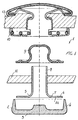
- Said back-male assembly comprises a back-male element 5 thereon a first fabric flap 11, or any other desired material, is clamped by a male element 9.
- Said male element 9 back-male 5 assembly is specifically designed for engaging with a female portion 10 in turn coupled to a second fabric flap 13 or the like.
- the back-male 5 has a substantially T-shape cross section and comprises a head 4 and a stem 8 arranged cross-wise of said head.
- a cap 2 preferably made of a plastic material, is applied.
- Said cap comprises a flat bottom 3, thereon, at the side of and in the direction of the head 4 of the back-male 5, an edge 6, adapted to be upturned and clamped on said surface 7 of said head 7 is provided.
- the cap 2 is affixed to the head 4 of the back-male element 5 by causing the bottom 3 to adhere to the surface 14 of said back-male head 4 and by clamping the edge 6 of the cap along the contour of the head 4 and against the surface 7 thereof.
- the size of the upturned edge 6 is so designed as to cover a broad portion of the top surface 7 of the head 4, to cooperate with a corresponding portion of the surface 12 of the bottom 15 of the male element 9 to held said fabric flap 11 therebetween ( Figure 3).
- the cooperation of the upturned edge 6 of the cap 2 and corresponding portion 12 of the bottom 15 of the male element 9 will improve the clamping of the snap fastener to the fabric flap 11, pressed therebetween, thereby providing a firm connection and preventing a possible damage of the fabric from detaching the snap fastener.
- the upturned arrangement of the edge 6 of the cap 2 on the back-male element 5 head 4 providing the above mentioned reinforcement function of the snap fastener clamped on the fabric, will provide a simultaneous covering of the head 4 of the back male 5.
- This covering in actual practice, is provided by the disclosed flat bottom 3 fully covering the exposed to the view portion of the head 4 of the back male 5, to provide the desired chromatic effects, as well as allowing figures, marks, signs and the like to be easily applied.
- the invention can be easily used for making any desired types of snap fasteners, such as that type of snap fastener including a parallel or round spring on the female portion thereof, or including a back male element having a tubular or pointed stem.
- the invention can be also applied to jeans snap fastener, by providing an upturned edge cap on the head of the nail element to be affixed in the jeans snap fastener.
- an upturned edge cap on the head of the nail element to be affixed in the jeans snap fastener.
- a cooperation between the upturned edges of the cap on the head and the snap fastener stem, favoring a proper clamping of the snap fastener to the fabric material, will be obtained.
Abstract
Description
- The present invention relates to an improved back-male assembly for snap fasteners in general, and a snap-fastener including this back-male assembly.
- More specifically, the field of the invention is that of the snap fasteners used for quickly closing cloth article flaps, leather article flaps and the like.
- Said snap fasteners conventionally comprise a male portion or assembly riveted on a back-male portion or assembly, therebetween a reinforcement washer, threaded axially on the back-male assembly stem is arranged. The thus made back-male assembly can be easily fitted on the female portion of the snap fastener, to which a corresponding clamping head is riveted.
- The above mentioned snap fasteners and, in particular, the snap fasteners including a reinforcement washer therein, have the drawback that they are rather complex construction-wise. In fact, the provision of said reinforcement washer requires a pre-assembling of said reinforcement washer on the stem of the back-male element, with the consequent requirement of performing a perfect centering of the two portions and threading the washer on the stem, with a consequent increase of the making cost.
- Moreover, prior reinforcement washer-snap fastener arrangements have the further disadvantage that the operation for applying thereto a covering cap, to be arranged on the back-male head, to provide the snap fastener with a desired aesthetic aspect, is very difficult.
- Actually, the application of the mentioned cover cap, in the presence of a reinforcement washer, would provide an excessive thickness, which would be antiaesthetic, as well as of difficult and expensive making.
- Accordingly, the main object of the present invention is to provide a novel back-male assembly or element for snap fasteners in general which, differently from prior back-male assemblies, does not require any provision of a reinforcement washer and which, moreover, can be easily and quickly coupled to a covering cap for covering the back-male assembly head.
- A further object of the invention is to provide a snap-fastener including the mentioned back-male assembly.
- The above mentioned object, as well as yet other objects, which will become more apparent hereinafter, are achieved by an improved back-male assembly and snap fastener respectively according to
Claims 1 and 7. Preferred embodiments of the invention are defined in the dependent claims. - Thus, the snap fastener according to the present invention provides a lot of advantages.
- At first, the construction of the snap fastener is very simplified, since it does not include any reinforcement washers, while providing the same effect as that provided by a conventional reinforcement washer.
- Moreover, the assembling operations of the snap fastener are made much quicker, since on the back-male assembly of the snap fastener no reinforcement washer must be mounted.
- Finally, the snap fastener according to the present invention comprises a covering cap for covering the back-male assembly head, thereby providing it with a desired aesthetic and ornamental pattern.
- The above mentioned objects, characteristics and advantages will become more apparent hereinafter from the following detailed disclosure of a preferred embodiment of the snap fastener according to the invention, being shown, by way of an indicative, but not limitative, example, in the figures of the accompanying drawings, where:
- Figure 1 is an exploded view showing an exemplary snap fastener including a back-male assembly or element according to the present invention;
- Figure 2 is a longitudinal cross-sectional view illustrating the back-male assembly of the snap fastener shown in Figure 1, an assembled cap being provided on the head thereof;
- Figure 3 shows the back-male assembly of Figure 2 including, riveted thereon, the snap fastener male element, applying an application to a fabric material or the like; and
- Figure 4 illustrates a modified embodiment of the counter-male assembly of Figure 3.
-
- The snap-fastener according to the present invention has been generally indicated in Figure 1 by the reference number 1. Said back-male assembly comprises a back-
male element 5 thereon afirst fabric flap 11, or any other desired material, is clamped by amale element 9. Saidmale element 9 back-male 5 assembly is specifically designed for engaging with afemale portion 10 in turn coupled to asecond fabric flap 13 or the like. - The back-
male 5 has a substantially T-shape cross section and comprises ahead 4 and a stem 8 arranged cross-wise of said head. Against thesurface 14 of the back-male 5 head, opposite to that 7 supporting the stem 8, acap 2, preferably made of a plastic material, is applied. Said cap comprises aflat bottom 3, thereon, at the side of and in the direction of thehead 4 of the back-male 5, anedge 6, adapted to be upturned and clamped on saidsurface 7 of saidhead 7 is provided. - As shown in Figure 2, the
cap 2 is affixed to thehead 4 of the back-male element 5 by causing thebottom 3 to adhere to thesurface 14 of said back-male head 4 and by clamping theedge 6 of the cap along the contour of thehead 4 and against thesurface 7 thereof. According to the invention, the size of theupturned edge 6 is so designed as to cover a broad portion of thetop surface 7 of thehead 4, to cooperate with a corresponding portion of thesurface 12 of thebottom 15 of themale element 9 to held saidfabric flap 11 therebetween (Figure 3). - Preferably, if "L" is the width of the
bottom 15 of themale element 9 and "I" is the width of theedge portion 6 of theupturned cap 2 of thehead 4 of the back-male 5, then the ratio L/I will vary from 1/1 and 2/1. The first of these embodiments is shown in Figure 4. According to an example of the invention, said sizes "L" of thebottom 15 and "I" of theedge 6 upturned portion are respectively of 2.7 mm and 2 mm. - Thus, the cooperation of the
upturned edge 6 of thecap 2 andcorresponding portion 12 of thebottom 15 of themale element 9 will improve the clamping of the snap fastener to thefabric flap 11, pressed therebetween, thereby providing a firm connection and preventing a possible damage of the fabric from detaching the snap fastener. - Owing to the invention, and as is shown in Figure 3, the upturned arrangement of the
edge 6 of thecap 2 on the back-male element 5head 4, providing the above mentioned reinforcement function of the snap fastener clamped on the fabric, will provide a simultaneous covering of thehead 4 of theback male 5. This covering, in actual practice, is provided by the disclosedflat bottom 3 fully covering the exposed to the view portion of thehead 4 of theback male 5, to provide the desired chromatic effects, as well as allowing figures, marks, signs and the like to be easily applied. - The invention, as above disclosed and illustrated, can be easily used for making any desired types of snap fasteners, such as that type of snap fastener including a parallel or round spring on the female portion thereof, or including a back male element having a tubular or pointed stem.
- The invention can be also applied to jeans snap fastener, by providing an upturned edge cap on the head of the nail element to be affixed in the jeans snap fastener. In such a case too, in actual practice, a cooperation between the upturned edges of the cap on the head and the snap fastener stem, favoring a proper clamping of the snap fastener to the fabric material, will be obtained.
Claims (9)
- An improved back-male assembly for snap fasteners in general, of the type comprising a head and a stem, characterized in that said back-male assembly comprises reinforcement means for reinforcing a clamping of the snap fastener to a supporting material, said reinforcing means being integrated in a covering cap for covering said head of said back-male assembly.
- A back-male assembly according to Claim 1, characterized in that said back-male assembly comprises a cap including a bottom covering an exposed surface of said head of said back-male assembly, said reinforcing means comprising an edge made as a single piece with said cap, said edge being provided for being upturned about said head and above said head thereby covering at least a major portion of a surface of said head supporting said stem and arranged oppositely from said exposed surface.
- A snap fastener according to Claim 2, characterized in that said upturned edge portion is designed for cooperating with a corresponding portion of a surface of the bottom of said back-male assembly of the snap fastener, thereby clamping said supporting material flap and providing a reinforcement of the latter as clamped to said snap fastener.
- A back-male assembly, according to Claim 3, characterized in that a ratio L/I of a width of said bottom of said male element and L of a width of said edge portion of said cap varies from 1:1 top 2:1.
- A back-male assembly according to Claim 4, characterized in that said width of said bottom and said width of said upturned edge portion have respectively a value of 2.7 mm and 2 mm.
- A back-male assembly according to Claim 1, characterized in that said cap is made of a plastic material.
- A snap fastener of a type including a male and back-male assembly, clamped on a first material flap and a female portion clamped to a second material flap, characterized in that said back male assembly includes a cap having an upturned edge according to Claim 5.
- A snap fastener according to Claim 7, characterized in that said snap fastener comprises a parallel or round spring on said female portion, and a back-male element having a tubular or pointed stem.
- A jeans snap fastener, characterized in that said jeans snap fastener comprises a nail having a head including an upturned edge cap according to Claim 6.
Applications Claiming Priority (2)
| Application Number | Priority Date | Filing Date | Title |
|---|---|---|---|
| IT1999MI002088A IT1313772B1 (en) | 1999-10-06 | 1999-10-06 | IMPROVED COUNTERMASK FOR AUTOMATIC AND AUTOMATIC BUTTON EQUIPPED WITH THIS COUNTERMASK. |
| ITMI992088 | 1999-10-06 |
Publications (2)
| Publication Number | Publication Date |
|---|---|
| EP1090565A2 true EP1090565A2 (en) | 2001-04-11 |
| EP1090565A3 EP1090565A3 (en) | 2002-09-25 |
Family
ID=11383731
Family Applications (1)
| Application Number | Title | Priority Date | Filing Date |
|---|---|---|---|
| EP00120444A Withdrawn EP1090565A3 (en) | 1999-10-06 | 2000-09-19 | Stud member for a snap fastener |
Country Status (2)
| Country | Link |
|---|---|
| EP (1) | EP1090565A3 (en) |
| IT (1) | IT1313772B1 (en) |
Cited By (4)
| Publication number | Priority date | Publication date | Assignee | Title |
|---|---|---|---|---|
| EP1632143A2 (en) * | 2004-09-03 | 2006-03-08 | Ykk Corporation | Fixture and button |
| CN102858198A (en) * | 2010-02-26 | 2013-01-02 | Ykk株式会社 | Button fixing member and method for forming button fixing member, eyelet member and method for forming eyelet member |
| CN104939385A (en) * | 2014-03-26 | 2015-09-30 | Ykk株式会社 | Installing device used for hook fitting |
| CN110027455A (en) * | 2019-04-25 | 2019-07-19 | 傲科塑料制品(张家港)有限公司 | A kind of automotive seat buckle sealing strip |
Citations (3)
| Publication number | Priority date | Publication date | Assignee | Title |
|---|---|---|---|---|
| US1887466A (en) * | 1930-02-03 | 1932-11-08 | Puc Vojtech | Press fastener |
| US3975803A (en) * | 1974-05-21 | 1976-08-24 | Gondra Industries & Co. | Fastening snap |
| EP0487162A1 (en) * | 1990-11-22 | 1992-05-27 | UTMAC S.N.C. DI VILLA ERMANNO & C. | Improved press-stud |
-
1999
- 1999-10-06 IT IT1999MI002088A patent/IT1313772B1/en active
-
2000
- 2000-09-19 EP EP00120444A patent/EP1090565A3/en not_active Withdrawn
Patent Citations (3)
| Publication number | Priority date | Publication date | Assignee | Title |
|---|---|---|---|---|
| US1887466A (en) * | 1930-02-03 | 1932-11-08 | Puc Vojtech | Press fastener |
| US3975803A (en) * | 1974-05-21 | 1976-08-24 | Gondra Industries & Co. | Fastening snap |
| EP0487162A1 (en) * | 1990-11-22 | 1992-05-27 | UTMAC S.N.C. DI VILLA ERMANNO & C. | Improved press-stud |
Cited By (8)
| Publication number | Priority date | Publication date | Assignee | Title |
|---|---|---|---|---|
| EP1632143A2 (en) * | 2004-09-03 | 2006-03-08 | Ykk Corporation | Fixture and button |
| EP1632143A3 (en) * | 2004-09-03 | 2007-01-17 | Ykk Corporation | Fixture and button |
| CN100450390C (en) * | 2004-09-03 | 2009-01-14 | Ykk株式会社 | Fixture and button |
| CN102858198A (en) * | 2010-02-26 | 2013-01-02 | Ykk株式会社 | Button fixing member and method for forming button fixing member, eyelet member and method for forming eyelet member |
| CN102858198B (en) * | 2010-02-26 | 2015-06-17 | Ykk株式会社 | Button fixing member and method for forming button fixing member, eyelet member and method for forming eyelet member |
| CN104939385A (en) * | 2014-03-26 | 2015-09-30 | Ykk株式会社 | Installing device used for hook fitting |
| CN110027455A (en) * | 2019-04-25 | 2019-07-19 | 傲科塑料制品(张家港)有限公司 | A kind of automotive seat buckle sealing strip |
| CN110027455B (en) * | 2019-04-25 | 2024-03-29 | 傲科塑料制品(张家港)有限公司 | Automobile seat buckle sealing strip |
Also Published As
| Publication number | Publication date |
|---|---|
| ITMI992088A1 (en) | 2001-04-06 |
| ITMI992088A0 (en) | 1999-10-06 |
| EP1090565A3 (en) | 2002-09-25 |
| IT1313772B1 (en) | 2002-09-17 |
Similar Documents
| Publication | Publication Date | Title |
|---|---|---|
| US5160209A (en) | Fastener assembly for concealably fastening a paper retaining mechanism to a binder | |
| US3142878A (en) | Staple button fastener | |
| US4011635A (en) | Retainer clip | |
| CA2048560C (en) | Snap button | |
| US20060021198A1 (en) | Chromatic snap fastener | |
| US2322656A (en) | Snap fastener for trimming and like strips | |
| US1675787A (en) | Fastener | |
| CA1048235A (en) | Retainer clips | |
| EP1090565A2 (en) | Stud member for a snap fastener | |
| GB2119632A (en) | Button cover | |
| EP0960783A1 (en) | Trim assembly for vehicle and method for manufacturing the same | |
| US3783477A (en) | Snap fastener | |
| US4159542A (en) | Tie holder | |
| US4658845A (en) | Umbrella cloth mounting assembly and method | |
| US2286988A (en) | Molding and like fastener and installation thereof | |
| US2961723A (en) | Molding clip | |
| US4907320A (en) | Detachable drop-off-proof button | |
| US2106728A (en) | Separable fastener | |
| US5305772A (en) | Strut structure of a folding umbrella having a seamless umbrella cover | |
| US5201076A (en) | Tie tip | |
| US2377179A (en) | Loose-leaf binder | |
| US6062627A (en) | No-tabbing visor mounting pin | |
| US2057588A (en) | Securing trim material | |
| US3120685A (en) | Paper coat fastener | |
| US2350275A (en) | Means for mounting buttons and similar articles |
Legal Events
| Date | Code | Title | Description |
|---|---|---|---|
| PUAI | Public reference made under article 153(3) epc to a published international application that has entered the european phase |
Free format text: ORIGINAL CODE: 0009012 |
|
| AK | Designated contracting states |
Kind code of ref document: A2 Designated state(s): AT BE CH CY DE DK ES FI FR GB GR IE IT LI LU MC NL PT SE |
|
| AX | Request for extension of the european patent |
Free format text: AL;LT;LV;MK;RO;SI |
|
| RIN1 | Information on inventor provided before grant (corrected) |
Inventor name: RACCOSTA, SANDRO Inventor name: RACCOSTA, GAETANO |
|
| PUAL | Search report despatched |
Free format text: ORIGINAL CODE: 0009013 |
|
| AK | Designated contracting states |
Kind code of ref document: A3 Designated state(s): AT BE CH CY DE DK ES FI FR GB GR IE IT LI LU MC NL PT SE |
|
| AX | Request for extension of the european patent |
Free format text: AL;LT;LV;MK;RO;SI |
|
| 17P | Request for examination filed |
Effective date: 20021219 |
|
| AKX | Designation fees paid |
Designated state(s): AT BE CH CY DE DK ES FI FR GB GR IE IT LI LU MC NL PT SE |
|
| 17Q | First examination report despatched |
Effective date: 20030724 |
|
| 17Q | First examination report despatched |
Effective date: 20030724 |
|
| 17Q | First examination report despatched |
Effective date: 20030724 |
|
| STAA | Information on the status of an ep patent application or granted ep patent |
Free format text: STATUS: THE APPLICATION IS DEEMED TO BE WITHDRAWN |
|
| 18D | Application deemed to be withdrawn |
Effective date: 20080401 |