EP1090158B1 - Spraying method to form a thick coating of metal oxides - Google Patents
Spraying method to form a thick coating of metal oxides Download PDFInfo
- Publication number
- EP1090158B1 EP1090158B1 EP99926408A EP99926408A EP1090158B1 EP 1090158 B1 EP1090158 B1 EP 1090158B1 EP 99926408 A EP99926408 A EP 99926408A EP 99926408 A EP99926408 A EP 99926408A EP 1090158 B1 EP1090158 B1 EP 1090158B1
- Authority
- EP
- European Patent Office
- Prior art keywords
- coating
- substrate
- flame
- temperature
- spraying
- Prior art date
- Legal status (The legal status is an assumption and is not a legal conclusion. Google has not performed a legal analysis and makes no representation as to the accuracy of the status listed.)
- Expired - Lifetime
Links
Images


Classifications
-
- B—PERFORMING OPERATIONS; TRANSPORTING
- B05—SPRAYING OR ATOMISING IN GENERAL; APPLYING FLUENT MATERIALS TO SURFACES, IN GENERAL
- B05B—SPRAYING APPARATUS; ATOMISING APPARATUS; NOZZLES
- B05B12/00—Arrangements for controlling delivery; Arrangements for controlling the spray area
- B05B12/08—Arrangements for controlling delivery; Arrangements for controlling the spray area responsive to condition of liquid or other fluent material to be discharged, of ambient medium or of target ; responsive to condition of spray devices or of supply means, e.g. pipes, pumps or their drive means
- B05B12/084—Arrangements for controlling delivery; Arrangements for controlling the spray area responsive to condition of liquid or other fluent material to be discharged, of ambient medium or of target ; responsive to condition of spray devices or of supply means, e.g. pipes, pumps or their drive means responsive to condition of liquid or other fluent material already sprayed on the target, e.g. coating thickness, weight or pattern
-
- B—PERFORMING OPERATIONS; TRANSPORTING
- B05—SPRAYING OR ATOMISING IN GENERAL; APPLYING FLUENT MATERIALS TO SURFACES, IN GENERAL
- B05B—SPRAYING APPARATUS; ATOMISING APPARATUS; NOZZLES
- B05B12/00—Arrangements for controlling delivery; Arrangements for controlling the spray area
- B05B12/08—Arrangements for controlling delivery; Arrangements for controlling the spray area responsive to condition of liquid or other fluent material to be discharged, of ambient medium or of target ; responsive to condition of spray devices or of supply means, e.g. pipes, pumps or their drive means
- B05B12/10—Arrangements for controlling delivery; Arrangements for controlling the spray area responsive to condition of liquid or other fluent material to be discharged, of ambient medium or of target ; responsive to condition of spray devices or of supply means, e.g. pipes, pumps or their drive means responsive to temperature or viscosity of liquid or other fluent material discharged
-
- B—PERFORMING OPERATIONS; TRANSPORTING
- B05—SPRAYING OR ATOMISING IN GENERAL; APPLYING FLUENT MATERIALS TO SURFACES, IN GENERAL
- B05B—SPRAYING APPARATUS; ATOMISING APPARATUS; NOZZLES
- B05B13/00—Machines or plants for applying liquids or other fluent materials to surfaces of objects or other work by spraying, not covered by groups B05B1/00 - B05B11/00
- B05B13/02—Means for supporting work; Arrangement or mounting of spray heads; Adaptation or arrangement of means for feeding work
- B05B13/04—Means for supporting work; Arrangement or mounting of spray heads; Adaptation or arrangement of means for feeding work the spray heads being moved during spraying operation
- B05B13/0436—Installations or apparatus for applying liquid or other fluent material to elongated bodies, e.g. light poles, pipes
-
- B—PERFORMING OPERATIONS; TRANSPORTING
- B05—SPRAYING OR ATOMISING IN GENERAL; APPLYING FLUENT MATERIALS TO SURFACES, IN GENERAL
- B05B—SPRAYING APPARATUS; ATOMISING APPARATUS; NOZZLES
- B05B13/00—Machines or plants for applying liquids or other fluent materials to surfaces of objects or other work by spraying, not covered by groups B05B1/00 - B05B11/00
- B05B13/02—Means for supporting work; Arrangement or mounting of spray heads; Adaptation or arrangement of means for feeding work
- B05B13/04—Means for supporting work; Arrangement or mounting of spray heads; Adaptation or arrangement of means for feeding work the spray heads being moved during spraying operation
- B05B13/0463—Installation or apparatus for applying liquid or other fluent material to moving work of indefinite length
- B05B13/0468—Installation or apparatus for applying liquid or other fluent material to moving work of indefinite length with reciprocating or oscillating spray heads
- B05B13/0473—Installation or apparatus for applying liquid or other fluent material to moving work of indefinite length with reciprocating or oscillating spray heads with spray heads reciprocating along a straight line
-
- C—CHEMISTRY; METALLURGY
- C23—COATING METALLIC MATERIAL; COATING MATERIAL WITH METALLIC MATERIAL; CHEMICAL SURFACE TREATMENT; DIFFUSION TREATMENT OF METALLIC MATERIAL; COATING BY VACUUM EVAPORATION, BY SPUTTERING, BY ION IMPLANTATION OR BY CHEMICAL VAPOUR DEPOSITION, IN GENERAL; INHIBITING CORROSION OF METALLIC MATERIAL OR INCRUSTATION IN GENERAL
- C23C—COATING METALLIC MATERIAL; COATING MATERIAL WITH METALLIC MATERIAL; SURFACE TREATMENT OF METALLIC MATERIAL BY DIFFUSION INTO THE SURFACE, BY CHEMICAL CONVERSION OR SUBSTITUTION; COATING BY VACUUM EVAPORATION, BY SPUTTERING, BY ION IMPLANTATION OR BY CHEMICAL VAPOUR DEPOSITION, IN GENERAL
- C23C14/00—Coating by vacuum evaporation, by sputtering or by ion implantation of the coating forming material
- C23C14/22—Coating by vacuum evaporation, by sputtering or by ion implantation of the coating forming material characterised by the process of coating
- C23C14/34—Sputtering
- C23C14/3407—Cathode assembly for sputtering apparatus, e.g. Target
- C23C14/3414—Metallurgical or chemical aspects of target preparation, e.g. casting, powder metallurgy
-
- C—CHEMISTRY; METALLURGY
- C23—COATING METALLIC MATERIAL; COATING MATERIAL WITH METALLIC MATERIAL; CHEMICAL SURFACE TREATMENT; DIFFUSION TREATMENT OF METALLIC MATERIAL; COATING BY VACUUM EVAPORATION, BY SPUTTERING, BY ION IMPLANTATION OR BY CHEMICAL VAPOUR DEPOSITION, IN GENERAL; INHIBITING CORROSION OF METALLIC MATERIAL OR INCRUSTATION IN GENERAL
- C23C—COATING METALLIC MATERIAL; COATING MATERIAL WITH METALLIC MATERIAL; SURFACE TREATMENT OF METALLIC MATERIAL BY DIFFUSION INTO THE SURFACE, BY CHEMICAL CONVERSION OR SUBSTITUTION; COATING BY VACUUM EVAPORATION, BY SPUTTERING, BY ION IMPLANTATION OR BY CHEMICAL VAPOUR DEPOSITION, IN GENERAL
- C23C4/00—Coating by spraying the coating material in the molten state, e.g. by flame, plasma or electric discharge
- C23C4/04—Coating by spraying the coating material in the molten state, e.g. by flame, plasma or electric discharge characterised by the coating material
- C23C4/10—Oxides, borides, carbides, nitrides or silicides; Mixtures thereof
- C23C4/11—Oxides
-
- C—CHEMISTRY; METALLURGY
- C23—COATING METALLIC MATERIAL; COATING MATERIAL WITH METALLIC MATERIAL; CHEMICAL SURFACE TREATMENT; DIFFUSION TREATMENT OF METALLIC MATERIAL; COATING BY VACUUM EVAPORATION, BY SPUTTERING, BY ION IMPLANTATION OR BY CHEMICAL VAPOUR DEPOSITION, IN GENERAL; INHIBITING CORROSION OF METALLIC MATERIAL OR INCRUSTATION IN GENERAL
- C23C—COATING METALLIC MATERIAL; COATING MATERIAL WITH METALLIC MATERIAL; SURFACE TREATMENT OF METALLIC MATERIAL BY DIFFUSION INTO THE SURFACE, BY CHEMICAL CONVERSION OR SUBSTITUTION; COATING BY VACUUM EVAPORATION, BY SPUTTERING, BY ION IMPLANTATION OR BY CHEMICAL VAPOUR DEPOSITION, IN GENERAL
- C23C4/00—Coating by spraying the coating material in the molten state, e.g. by flame, plasma or electric discharge
- C23C4/12—Coating by spraying the coating material in the molten state, e.g. by flame, plasma or electric discharge characterised by the method of spraying
- C23C4/123—Spraying molten metal
-
- C—CHEMISTRY; METALLURGY
- C23—COATING METALLIC MATERIAL; COATING MATERIAL WITH METALLIC MATERIAL; CHEMICAL SURFACE TREATMENT; DIFFUSION TREATMENT OF METALLIC MATERIAL; COATING BY VACUUM EVAPORATION, BY SPUTTERING, BY ION IMPLANTATION OR BY CHEMICAL VAPOUR DEPOSITION, IN GENERAL; INHIBITING CORROSION OF METALLIC MATERIAL OR INCRUSTATION IN GENERAL
- C23C—COATING METALLIC MATERIAL; COATING MATERIAL WITH METALLIC MATERIAL; SURFACE TREATMENT OF METALLIC MATERIAL BY DIFFUSION INTO THE SURFACE, BY CHEMICAL CONVERSION OR SUBSTITUTION; COATING BY VACUUM EVAPORATION, BY SPUTTERING, BY ION IMPLANTATION OR BY CHEMICAL VAPOUR DEPOSITION, IN GENERAL
- C23C4/00—Coating by spraying the coating material in the molten state, e.g. by flame, plasma or electric discharge
- C23C4/12—Coating by spraying the coating material in the molten state, e.g. by flame, plasma or electric discharge characterised by the method of spraying
- C23C4/129—Flame spraying
-
- H—ELECTRICITY
- H10—SEMICONDUCTOR DEVICES; ELECTRIC SOLID-STATE DEVICES NOT OTHERWISE PROVIDED FOR
- H10N—ELECTRIC SOLID-STATE DEVICES NOT OTHERWISE PROVIDED FOR
- H10N60/00—Superconducting devices
- H10N60/01—Manufacture or treatment
- H10N60/0268—Manufacture or treatment of devices comprising copper oxide
- H10N60/0296—Processes for depositing or forming copper oxide superconductor layers
- H10N60/0492—Processes for depositing or forming copper oxide superconductor layers by thermal spraying, e.g. plasma deposition
-
- B—PERFORMING OPERATIONS; TRANSPORTING
- B05—SPRAYING OR ATOMISING IN GENERAL; APPLYING FLUENT MATERIALS TO SURFACES, IN GENERAL
- B05B—SPRAYING APPARATUS; ATOMISING APPARATUS; NOZZLES
- B05B7/00—Spraying apparatus for discharge of liquids or other fluent materials from two or more sources, e.g. of liquid and air, of powder and gas
- B05B7/16—Spraying apparatus for discharge of liquids or other fluent materials from two or more sources, e.g. of liquid and air, of powder and gas incorporating means for heating or cooling the material to be sprayed
- B05B7/20—Spraying apparatus for discharge of liquids or other fluent materials from two or more sources, e.g. of liquid and air, of powder and gas incorporating means for heating or cooling the material to be sprayed by flame or combustion
- B05B7/201—Spraying apparatus for discharge of liquids or other fluent materials from two or more sources, e.g. of liquid and air, of powder and gas incorporating means for heating or cooling the material to be sprayed by flame or combustion downstream of the nozzle
- B05B7/205—Spraying apparatus for discharge of liquids or other fluent materials from two or more sources, e.g. of liquid and air, of powder and gas incorporating means for heating or cooling the material to be sprayed by flame or combustion downstream of the nozzle the material to be sprayed being originally a particulate material
- B05B7/206—Spraying apparatus for discharge of liquids or other fluent materials from two or more sources, e.g. of liquid and air, of powder and gas incorporating means for heating or cooling the material to be sprayed by flame or combustion downstream of the nozzle the material to be sprayed being originally a particulate material in a container fixed to the discharge device
-
- Y—GENERAL TAGGING OF NEW TECHNOLOGICAL DEVELOPMENTS; GENERAL TAGGING OF CROSS-SECTIONAL TECHNOLOGIES SPANNING OVER SEVERAL SECTIONS OF THE IPC; TECHNICAL SUBJECTS COVERED BY FORMER USPC CROSS-REFERENCE ART COLLECTIONS [XRACs] AND DIGESTS
- Y10—TECHNICAL SUBJECTS COVERED BY FORMER USPC
- Y10S—TECHNICAL SUBJECTS COVERED BY FORMER USPC CROSS-REFERENCE ART COLLECTIONS [XRACs] AND DIGESTS
- Y10S428/00—Stock material or miscellaneous articles
- Y10S428/922—Static electricity metal bleed-off metallic stock
- Y10S428/9265—Special properties
- Y10S428/93—Electric superconducting
-
- Y—GENERAL TAGGING OF NEW TECHNOLOGICAL DEVELOPMENTS; GENERAL TAGGING OF CROSS-SECTIONAL TECHNOLOGIES SPANNING OVER SEVERAL SECTIONS OF THE IPC; TECHNICAL SUBJECTS COVERED BY FORMER USPC CROSS-REFERENCE ART COLLECTIONS [XRACs] AND DIGESTS
- Y10—TECHNICAL SUBJECTS COVERED BY FORMER USPC
- Y10S—TECHNICAL SUBJECTS COVERED BY FORMER USPC CROSS-REFERENCE ART COLLECTIONS [XRACs] AND DIGESTS
- Y10S505/00—Superconductor technology: apparatus, material, process
- Y10S505/725—Process of making or treating high tc, above 30 k, superconducting shaped material, article, or device
- Y10S505/737—From inorganic salt precursors, e.g. nitrates
-
- Y—GENERAL TAGGING OF NEW TECHNOLOGICAL DEVELOPMENTS; GENERAL TAGGING OF CROSS-SECTIONAL TECHNOLOGIES SPANNING OVER SEVERAL SECTIONS OF THE IPC; TECHNICAL SUBJECTS COVERED BY FORMER USPC CROSS-REFERENCE ART COLLECTIONS [XRACs] AND DIGESTS
- Y10—TECHNICAL SUBJECTS COVERED BY FORMER USPC
- Y10S—TECHNICAL SUBJECTS COVERED BY FORMER USPC CROSS-REFERENCE ART COLLECTIONS [XRACs] AND DIGESTS
- Y10S505/00—Superconductor technology: apparatus, material, process
- Y10S505/80—Material per se process of making same
- Y10S505/815—Process of making per se
- Y10S505/818—Coating
Definitions
- the present invention relates to a composite and a method of spraying to form a coating on flat or curved substrates, for example, either as part of the direct formation of metallic or ceramic coatings such as superconductive or piezo-electric layers or for the production of targets for sputtering magnetrons having coatings which are precursors of such layers.
- EP-A-286 135 it is known to flame spray complex ceramic materials onto a substrate such as a tape to form a superconducting layer. It is suggested to pre-heat the substrate to temperatures above 540°C and to cool the coating slowly. It is further recommended to treat the coating in an atmosphere containing one of the components of the superconducting ceramic. An oxy-acetylene flame is used for the flame spraying. Thickness of up to 3 mm are described.
- EP-A-355 736 describes production of flat targets with metal oxides up to a layer thickness of 3 mm.
- WO 98/0833 describes the production of ⁇ 20 micron thick layers of superconducting metal oxide mixtures.
- EP-A-586 809 describes the metal spraying application of a layer of relatively homogeneous material (nickel coated silicon) which is much easier to handle than the heterogeneous oxide mixtures contemplated by the present invention. Layer thicknesses of up to 8 mm are described but 3 to 5 mm is preferred. Various layers are proposed including a Ni-Al layer for improving adhesion between the deposited layer and the substrate. A Ni-Al adhesion promoter is known from DE-A-33 18 828.
- Plasma spraying of superconducting materials is described in EP-A-288711 up to a thickness of 250 micron.
- One aspect of the present invention is to provide a substrate with a coating of a combination of metal oxides having a thickness greater than 5 mm, and more preferably greater than 8 mm.
- the deposited coating comprises the addition of a noble metal, preferably about 20% or up to 30%, to increase thermal conductivity of the coating.
- the noble metal is preferably silver.
- the noble metal may be included as a salt or oxide, e.g. silver nitrate or silver oxide, in the material to be sprayed.
- the coating is deposited by flame or plasma spraying at atmospheric pressure.
- the substrate is cylindrical and is more preferably is suitable as a cylindrical target substrate for a sputtering magnetron.
- the combination of oxides preferably comprises at least a superconductive precursor or a superconductor and at least 10% of the coating is in a superconductive phase as deposited.
- the thermal conductivity of the deposited material is preferably between 1 and 5 Wm -1 K -1 .
- the thermal conductivity of the composite preferably lies within the range 25 to 125 Wm -1 K -1 . These values are particularly preferred for YBa 2 Cu 3 O 7 coatings.
- an adhesion promoter layer is applied onto the substrate before application of the coating of the metal oxide combination.
- the adhesion promoter may be a layer of Ni-Al or a layer of an In-alloy, for example.
- the deposited coating is preferably impact resistant, e.g.
- the electrical resistivity of the deposited layer is lower than 15 x 10 -6 Ohm.m, more preferably lower than 10 x 10 -6 and most preferably less than 5 x 10 -6 Ohm.m. Values below 1 x 10 -6 Ohm.m can be achieved. Up to 30% of a noble metal such as silver may be added to lower the resistivity. These values are particularly preferred for YBa 2 Cu 3 O 7 coatings.
- the electrical , thermal and mechanical properties of the coating deposited in accordance with the present invention should be sufficient that the deposited layer can be applied to a suitable substrate by means of a sputtering magnetron preferably at a static sputtering deposition speed of at least 5 nm/minute, more preferably, at 20 nm/minute and most preferably at at least 40 nm/minute.
- a superconductor precursor or a superconductive material When a superconductor precursor or a superconductive material is deposited, at least 10% of the coating is in the superconducting phase as deposited, more preferably 15%. This may be assisted by a subsequent limited thermal treatment, e.g. 3 hours and 940°C, after deposition.
- the present invention also includes a method of depositing by flame or plasma spraying at atmospheric pressure a layer onto a substrate to form a target for a sputtering magnetron the layer having a thickness of at least 3 mm, preferably more than 5 mm and more preferably greater than 8 mm, the coating comprising metal oxides, and the method including the step of depositing an additional nobel metal with the coating and during deposition of the coating, cooling the substrate so that the solidified coating thereon has a temperature between 25 and 150°C.
- the substrate may be a target for a sputtering magnetron and the final coating may sputtered onto a final substrate in the sputtering magnetron.
- the flame of the flame spray gun preferably imparts a temperature to the powder to be sprayed of 1500°C or less, preferably 1200°C or less. Preferably the temperature imparted may be a little higher than the melting point of the powder to be sprayed, e.g. 600 to 1000°C for some metal oxides.
- the substrate is preferably cooled by bringing a cryogenic fluid into contact with the substrate.
- the cooling device should maintain the solidified coating at a temperature between room temperature ( ⁇ 25°C) and 150°C, more preferably between room temperature ( ⁇ 25°C) and 100 °C.
- the above methods may be used, for example, either as part of the direct formation of superconductive or piezo-electric layers on the substrate, e.g. a tape, or for the production of coatings on targets for use in a sputtering magnetron to sputter a superconducting layer onto a final substrate.
- the present invention may provide oxide sputtering targets supporting very high power dissipation thus enabling high sputter deposition rates of at least 50 nm/min.
- the present invention will be described with reference to certain specific embodiments and with reference to certain specific drawings but the invention is not limited thereto but only by the claims.
- the present invention will mainly be described with reference to the deposition of a superconductor precursor or superconductive coatings but the invention is not limited thereto but may be used advantageously with other heterogeneous coatings such as ceramic coatings, particularly those having special properties such as piezo-electric coatings and in particular coatings which contain components which can be degraded by high temperatures or which are more volatile than other components.
- the present invention will be described with reference to the manufacture of YBa 2 Cu 3 O 7 superconducting powders and coatings but the invention is not limited thereto but only by the claims.
- metal oxide combination coatings suitable for use as a sputtering magnetron target have been applied by oxy-acetylene flame spraying with water cooling or by atmospheric pressure or low-pressure plasma spraying to substrates including cylindrical substrates used in rotating cathode magnetrons.
- plasma spraying gasses may be used such as argon or mixtures of argon and other gasses to shield the plasma spray.
- present invention will mainly be described with reference to an input to the flame spraying head of spray dried powder.
- the present invention is not limited thereto but includes other forms of input materials such as a mixture of the metal oxides, including slurries thereof or mixtures of precursors of metal oxides such as metal nitrates as well as slurries and solutions thereof.
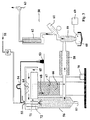
- Fig. 1 is a schematic diagram of the flame spraying apparatus 10 which can be used with embodiments of the present invention.
- a flame spraying gun is represented schematically at 12.
- the gun 12 may be a commercially available flame spraying gun as for instance available from Sulzer Metco, Westbury, NY, USA or a high velocity oxy-fuel spraying gun available from the same company.
- the gun 12 may be provided with an air pincher.
- the gun 12 may be fed with fuel gas in pipe 22, oxygen in pipe 23 and gun cooling air in pipe 24. Additional gases may be supplied to the gun 12 as described for instance in US 5,273,957 or EP-A-413 296.
- Material to be coated is fed in powder or liquid form, e.g.
- Gun 12 is mounted on a drive (not shown) which provides the necessary movements of the gun 12 to coat the substrate 19.
- substrate 19 is a cylindrical target, for instance, for a rotating cathode magnetron, this may be rotated and the movements of the gun 12 may be simple reciprocating movements parallel to the axis of the target 19.
- the movements may be provided by a suitable robot and may be complex, e.g. including rotational cycloidal motions.
- several guns 12 may spray the same substrate 19 at the same time.
- the fuel gas for the gun 12 may be selected from one of acetylene, propylene, hydrogen or similar fuels but the present invention is not necessarily limited thereto.
- Particularly preferred in one embodiment of the present invention is a fuel with a lower calorific value such as one of ethylene, natural or town gas, butane or propane as these provide a lower temperature flame than acetylene and butane is particularly preferred as it gives a stable easily controllable flame and is considered safer than acetylene if powders containing copper compounds are used. It is generally accepted that oxy-acetylene flames have temperatures of 2000 °C and more.
- the flame of the flame spraying gun 12 imparts a temperature only sufficient to just melt the powder to be sprayed. Temperatures of 1500 °C or less and preferably 1200 °C or less are preferred and temperatures between 600 and 1000 °C may be more preferable. These low flame temperatures minimise decomposition of the ceramic powder components during flame spraying. Moreover, they limit the impact of evaporation of the materials to be flame sprayed and allow a deposition efficiency of more than 80%, i.e. more than 80% of the solid mass originally introduced into the gun 12, becomes attached to the substrate 19. Mechanically stable, scratch resistant flame sprayed coatings are produced with these low temperatures.
- the gun 12 is preferably held at 7 to 15 cm from the substrate 19 to be coated but this depends upon the size of the flame. Similar coatings have been obtained using both oxy-acetylene flame spraying and plasma spraying. Attention must be paid to the energy taken up by the sprayed particles during the spraying and the transfer of this energy to the substrate. Intensive cooling of the substrate is preferred which may be on the side of the substrate remote from the deposited layer and/or on the same side. By altering the velocity of the particles in the flame or plasma the dwell time therein may be altered, thus limiting the energy uptake by the particles.
- the material of substrate 19 preferably has a high melt temperature and a high thermal conductivity and when the substrate 19 is to be used as a target for a sputtering magnetron a good electrical conductivity is preferable. It is also preferred if the thermal expansion of the substrate material is similar to that of the ceramic coating to be applied. In accordance with embodiments of the present invention low temperature flame spraying and/or intense cooling of the substrate 19 allows the use of substrates 19 with a thermal expansion coefficient up to at least twice or down to at least a half of the thermal expansion coefficient of the ceramic coating.
- a non-limiting list of suitable materials may be steel, iron, stainless steel, copper or copper alloys, however the low temperature flame spraying process in accordance with the present invention, either independently or in combination with intense cryogenic cooling of the substrate 19, allows other materials to be used such as paper, cardboard or polymeric materials.
- the substrate 19 should be free of grease and dry before deposition.
- the outer surface of metals is sand blasted and then lapped with abrasive materials. Buffer layers between the substrate and the sprayed coating may be used such as Ni-Al or an In-alloy. These may be applied by flame or plasma spraying before application of the metal oxide coating.
- the substrate 19 is rigid it may be mounted in a suitable jig.
- a cylindrical substrate 19 is preferably mounted in a rotating device such as a lathe.
- the substrate 19 may be held by rotatable chucks at each end thereof.
- the temperature of the solidified flame sprayed coating 40 on the surface of the substrate 19 is preferably measured by a temperature sensor 13, 15.
- the sensor head 13 is preferably a remote sensing optical head which is not in contact with the surface 40 of the flame sprayed coating.
- the temperature to be measured is of the solidified coating 40 and not that of the coating immediately on impacting the substrate 19 which may have a higher temperature.
- the temperature sensor 13 is preferably mounted so that it lags behind the impact position of the flame sprayed materials a little.
- a temperature sensor 31 may be provided inside the substrate 19 for further control of the deposition process.
- Control of deposition temperature is an important aspect of the present invention. Control of temperature affects the amount of thermal stress in the coating, a low stress reducing the possibility of cracks forming in the coating.
- a means for intense cooling of the substrate 19 is provided.
- This is preferably a cryogenic cooler comprising a supply 16 of cryogenic fluid and a delivery system 11, 14, 17, 29, 30.
- the delivery system may be adapted to the form of the substrate 19.
- the cooling device may be a conduit 17 for supplying the cryogenic fluid to a control valve 11, a conduit 30 with regularly spaced holes 29 for distribution of the cryogenic fluid inside the substrate 19 and a control device 14 for receiving the output of the temperature sensor 13, 15 and for controlling the operation of the control valve 11 so as to maintain the surface temperature of the solidified coating 40 to within a certain range.
- a temperature range from room temperature (25 to 30°C) to 150 °C and more preferably room temperature to 100 °C. These low temperatures avoid thermal stresses between the coating 40 and the substrate 19 providing a good bond and good coating density, hardness and scratch resistance thus helping to ensure the long term stability of such a coating.
- a cryogenic fluid such as liquid nitrogen (77 °K) is quite advantageous and economical as it does not require the complication of perfectly sealed rotating inlets and outlets to the substrate 19 when water or other liquid coolants are used. Additionally, cryogenic fluids such as liquid nitrogen produce large temperature gradients, thus increasing the thermal sink-effect. Other liquid coolants such as water are not excluded from the present invention.
- the cylindrical substrate 19 may be sealed by a seal 26 at one end and with a rotating seal 28 at the other.
- the seal 28 may be provided with a sealed feedthrough 27 for the supply of cryogenic fluid. If water cooling is used, rotating seals at both ends of the cylindrical substrate are considered very important to prevent escape of water vapour into the deposition environment.
- the ends 26, 27 allow escape of a cryogenic fluid which then forms a shield gas around substrate 19 during the spraying process.
- cryogenic fluids are liquid nitrogen, liquid oxygen and liquid air.
- a shield gas including oxygen e.g.
- liquid air or liquid oxygen which may help to reoxidise the reduced component.
- liquid nitrogen would be preferred, or a reducing gas may be included such as hydrogen.
- the deposition rate is selected in order to maintain the substrate surface temperatures mentioned above.
- the rotation speed of the substrate 19 the linear speed of the gun 12 and the rate of material exiting the gun 12 may be controlled to achieve the temperatures specified above.
- a powder delivery of 5-10 g/min was suitable to produce 3-10 mm coatings when depositing a YBa 2 Cu 3 O 7 layer.
- the rotational speed of the substrate 19 may be in the range 10 to 100 RPM with a surface speed in the range 1 to 40 m/min and the longitudinal feed of the gun 12 in the range 1-3 m/min, typically 2 m/min.
- the deposition rate per reciprocating pass of the gun 12 may be 10 to 50 micron thickness of the coating. About 10% to 15% of the deposited coating had maintained the lattice structure of the powder and exhibited superconducting properties. It will be appreciated by the skilled person that increasing the deposition speed, deposition thickness per pass or the flame temperature or reducing the thermal conductivity of the substrate material will increase the thermal load on the cooling system and adjustments of one or more of these parameters may be necessary to obtain satisfactory coatings.
- the thermal conductivity of the deposited material is preferably between 1 and 5 Wm -1 K -1 When deposited on a steel substrate the thermal conductivity preferably lies within the range 25 to 125 Wm -1 K -1 . These values are particularly preferred for YBa 2 Cu 3 O 7 coatings.
- an adhesion promoter layer is applied onto the substrate before application of the coating of the metal oxide combination.
- the adhesion promoter may be a layer of Ni-Al or a layer of an In-alloy, for example.
- the deposited coating is preferably impact resistant, e.g. withstands impact of a 0.036 kg steel ball from a height of 2 metres.
- about 20% or up to 30% of a noble metal is included in the oxide material to improve electrical and thermal properties of the deposited layer.
- the noble metal is preferably silver.
- the noble metal may in included as a salt or oxide, e.g. silver nitrate or silver oxide, in the material to be sprayed.
- the electrical resistivity of the deposited layer is lower than 15 x 10 -6 Ohm.m, more preferably lower than 10 x 10 -6 and most preferably less than 5 x 10 -6 Ohm.m. Values below 1 x 10 -6 Ohm.m can be achieved. Up to 30% of a noble metal such as silver may be added to lower the resistivity. These values are particularly preferred for YBa 2 Cu 3 O 7 coatings.
- Fig. 2 is a schematic representation of a further embodiment of the flame spraying process and apparatus in accordance with the present invention. Components in Fig. 2 with the same reference numbers as in Fig. 1 refer to equivalent items.
- the substrate 19 in accordance with this embodiment is a foil or sheet of metal, plastic or other flexible material which is wound from a pay-off spool 32 to a take-up spool 36. Where the final coating 40 cannot be spooled, the foil with coating 14 may be drawn linearly from the pay-off spool 32 and cut into lengths.
- the coating 40 which may be a superconducting layer, is flame sprayed with a flame spray gun 12 similar to the one described with respect to Fig. 1.
- the temperature of the flame of the gun 12 imparts a temperature of 1500 °C or less, more preferably 1200 °C or less to the material being sprayed through the flame.
- This material may be in the form of powder either of finished components of the coating 40, e.g. oxides, or precursors thereof, e.g. nitrates, or may be in the form of a slurry of powders, e.g. oxides, or a solution, e.g. of nitrates.
- Gun 12 may be controlled by hand or more preferably by a robot to provide zigzag motions across the width of foil 19 thus applying an even coating 40.
- a layer of 10 to 50 micron thickness is applied in each pass.
- the temperature of the coating 40 may be monitored by one or more optical sensors 13, 15.
- the temperature of the foil 19 is regulated by means of a cryogenic fluid supplied from a container 16 to a series of holes or jets 29 via conduit 17, a controllable valve 11 and a conduit 30.
- the valve 11 is controlled by a controller 14 to maintain the temperature of the foil as determined by the sensor 13, 15 to less than 400 °C, preferably less than 150 °C and most preferably between 50 and 100 °C.
- Such low temperatures allow a wide range of materials for substrate 19 including polymeric materials, cellulosic materials as well as metals.
- the present invention includes several controllers each with its own controllable cryogenic cooling device 11, 29, 30 for individually controlling the temperature of different parts of the foil 19 or coating 40.
- an optical encoder 34 may be attached to a roller 35.
- the optical encoder may be read with an optical sensor 37, 38, the pulse frequency generated in the sensor 37, 38 being proportional to the linear speed of the foil 19. This value may also be used by the controller 14 to control the complete process to maintain the temperatures and coating thicknesses mentioned above.
- the coated substrates in accordance with this invention are preferably stored for long periods in a plastic bag filled with a dry inert gas such as dry nitrogen.
- a dry inert gas such as dry nitrogen.
- One aspect of the present invention is the flame spraying of powders which already have superconducting properties in the powder form. Using the methods in accordance with the present invention it is possible to flame spray such coatings and retain 10% to 15% of superconducting property of the coating 40 produced without extensive post-heat treatments.
- the superconducting and/or ceramic powder and/or metallic powder to be used for flame spraying is preferably homogeneous, exhibits the appropriate rheological properties and correct stoichiometry to generate the required properties in the final coating.
- Typical preferred densities for superconducting powders may lie in the range 4 to 5 g/cm 3 .
- a method for production of suitable ceramic powders for use with embodiments of the present invention is provided.
- a reactive precursor powder can be obtained using commercially available spray drying equipment in batches of kilograms.
- the type of salt (mostly nitrates) should preferably be compatible with thermal decomposition to oxides in further processes such as sintering or flame spraying.
- spray dried nitrate powders may be flame sprayed directly or the powders may first be sintered and then flame sprayed.
- a spray drying system 50 for delivery of powder suitable for subsequent flame spraying embodiments of the present invention is shown schematically in Fig. 3.
- the input liquid is drawn from a suitable source 53 via a peristaltic pump 54 to a spray head 71.
- Pressurised air 51 is drawn in through an air dryer and optional pre-heater 52 to the spray head 71 by a suction device such as a fan 63 at the end of the generally closed system.
- the liquid from source 53 enters the spray head 71 which is cooled by any suitable means 55 to prevent clogging due to early evaporation of the liquid.
- the liquid is atomised in a co-current two fluid nozzle 71 by the dry pressurised air 51 and discharged it into a chamber 56 where it dries to a powder.
- the liquid from source 53 may be a solution of suitable nitrates or a slurry of the relevant oxides with the addition of other agents such as binders.
- Air 65 is drawn in by fan 63 over a heater 64 and introduced into chamber 56 via a ring orifice 72 which surrounds the outlet of the spray head 71.
- the air 65 also heats the spray head 71.
- the circumferential air flow 65 guides the evaporating liquid in chamber 56 and helps to prevent the powder sticking to the walls of the chamber 56.
- the air throughput of fan 63 is chosen so that powder of the correct grain size is swept from chamber 36 through an optional heater section 58 into a powder collector 59. Heavier particles settle out in trap 57 and are removed from the bottom of chamber 56.
- the powder collector 59 may be any suitable device such as a cyclone, a bag filter or an electrostatic filter although a cyclone is preferred.
- the cyclone discharges the powder into a removable container 60 sealed to the bottom of the cyclone 59. Spent air is removed via the trap 61 and scrubbed in scrubber 12 to remove impurities. The final clean air is exhausted to atmosphere by the fan 63 which controls air flow through the system.
- the control system 66 - 70 for the process functions as follows.
- the rotational speed of the centrifugal air pump 53, the temperature of the heating element 64 and the flow of the atomised air are set with controller 67, 70.
- Air flow is measured by gauge 68.
- the temperature of the hot air 65 and the air in the tube leading from the chamber 56 to the optional heater 58 is monitored using thermocouples 66, whereas final powder temperature is monitored by temperature sensor 69.
- the powder may be sintered in a single step.
- a superconducting powder of the general formula YBa 2 Cu 3 O 7 with optional Ag the required nitrates are dissolved in water in the correct stoichiometric proportions and spray dried as indicated above.
- the nitrates are then reduced to oxides by sintering at 920 - 960 °C for 40 to 60 hours.
- the nitrates may first be reduced by heating in air at 780 °C for 10 hours before sintering at the above temperatures and times.
- the YBa 2 Cu 3 O 7 powder produced by this procedure is superconducting.
- On aspect of the present invention is to produce powders with superconducting properties by spray drying and optional sintering and then to flame spray these superconductive powders at the lowest flame temperatures necessary to obtain melting of the powder and coating formation on the substrate while cooling the coating in the fastest possible way.
- the crystal structure present in the superconducting powder is disturbed as little as possible by the flame spraying process.
- melting the powder during flame spraying causes complete loss of crystal organisation if the time in the melt is long.
- By lowering the flame temperature and shortening the time in the melt phase by cooling the coating very rapidly in accordance with the present invention some local crystal organisation is kept in the final flame sprayed coating, e.g.
- the powder for flame spraying may be spray dried from slurries of the relevant oxides in the correct stoichiometric proportions with the optional addition of silver in the above apparatus in accordance with the present invention.
- the mixture of oxides may be produced by individually sieving them to 40 micron and then mixing in the correct proportions to obtain the stoichiometric proportions in the final coating.
- a quantity of deionised water is added of about 60% by weight of the powder as well as a quantity of an organic binder such as PVA (polyvinyl acetate) equal to about 2% by weight of the powder and then mixed into a slurry.
- the slurry is then spray dried as described above resulting in powder with a grain size from 30 to 50 micron.
- spray dried oxide slurries do not require sintering before flame spraying.
- the organic binder may be burnt out during flame spraying or in a special sintering step.
- Spray drying of 10% by weight nitrate solutions generally produce grain sizes of 3 micron on average with at least 90% of the grains between 0.5 and 5 microns. In order to obtain the required grain size it is preferable to sinter as mentioned above. Light grinding and sieving of this sintered powder may produce a mass fraction of more than 80% with grain sizes between 40 and 80 micron.
- the present invention includes the addition of organic binders such as polyvinyl acetate (PVA) to the liquid to be spray dried to control grain size in the final powder.
- organic binders such as polyvinyl acetate (PVA)
- PVA polyvinyl acetate
- Such binders may be burnt out in a later high temperature process such as sintering.
- An average grain size of 40 to 80 microns is preferred for good flame spray deposition.
- the final powder may be lightly milled and sieved to be improve the homogeneity of grain sizes.
- One aspect of the present invention is the inclusion of silver metal in the final superconducting ceramic coating. This is achieved as mentioned above by inclusion of about 20% to 30% by weight of the ceramic materials of silver nitrate when nitrate solutions are spray dried and the flame sprayed or by addition of Ag 2 O powder in an oxide slurry which is then spray dried and flame sprayed.
- the addition of silver in the flame sprayed material is beneficial for the inter-grain adhesion and heat dispersal during flame spraying thus yielding a strong and dense coating.
- the silver improves the thermal and electrical conductivity of the flame sprayed coating which is beneficial to the sputtering process when the substrate is used as a sputtering target. The improved conductivities allow higher power throughput for the magnetron than targets not containing silver.
- the flame spraying process in accordance with the present invention allows the reconditioning of targets for sputtering magnetrons. It is well known that the presence of a static race-track plasma on a magnetron target during sputtering results in an erosion groove and poor target utilisation. Using the flame spraying process of the present invention such a worn target may be reconditioned by spraying the appropriate target material into the erosion groove and building up the target to its former thickness in these regions.
- the general target temperature may be kept below 400 °C, preferably below 150°C and most preferably between room temperature ( ⁇ 25°C) and 100°C. These low temperatures result in little damage to the existing target material while still providing a mechanically strong coating in the old erosion grooves.
- the flame spraying gun 12 described above may be hand held and the contour of the erosion groove in the used target followed building up the lost material slowly, preferably 10 to 50 micron per pass.
- the gun 12 is controlled by a robot which is programmed to execute the correct motions with the gun 12 to fill up the erosion groove in the target.
Landscapes
- Chemical & Material Sciences (AREA)
- Engineering & Computer Science (AREA)
- Mechanical Engineering (AREA)
- Chemical Kinetics & Catalysis (AREA)
- Materials Engineering (AREA)
- Metallurgy (AREA)
- Organic Chemistry (AREA)
- Plasma & Fusion (AREA)
- Physics & Mathematics (AREA)
- Manufacturing & Machinery (AREA)
- Coating By Spraying Or Casting (AREA)
- Superconductors And Manufacturing Methods Therefor (AREA)
- Physical Vapour Deposition (AREA)
- Catalysts (AREA)
- Oxygen, Ozone, And Oxides In General (AREA)
Abstract
Description
- The present invention relates to a composite and a method of spraying to form a coating on flat or curved substrates, for example, either as part of the direct formation of metallic or ceramic coatings such as superconductive or piezo-electric layers or for the production of targets for sputtering magnetrons having coatings which are precursors of such layers.
- From EP-A-286 135 it is known to flame spray complex ceramic materials onto a substrate such as a tape to form a superconducting layer. It is suggested to pre-heat the substrate to temperatures above 540°C and to cool the coating slowly. It is further recommended to treat the coating in an atmosphere containing one of the components of the superconducting ceramic. An oxy-acetylene flame is used for the flame spraying. Thickness of up to 3 mm are described.
- It is also known from US 5,196,400 to plasma spray a coating onto a target for use in a sputtering magnetron to sputter a Y-Ba-CuO superconductor coating. Deposition of only a thin target coating of 0.5 mm is reported.
- The production of superconducting powders using flame spraying is reported in US 5,140,005. An oxy-acetylene flame is used. It is tacitly accepted that the high temperature of the flame changes the stoichiometric ratios of the components and that this has to be compensated by increasing the more volatile components in the original mixtures. US 5,045,365 describes a method of cooling a oxy-acetylene flame-sprayed substrate with water. Without special precautions, water cooling is unsuitable for superconductors due to the water vapour produced.
- EP-A-355 736 describes production of flat targets with metal oxides up to a layer thickness of 3 mm. WO 98/0833 describes the production of < 20 micron thick layers of superconducting metal oxide mixtures.
- The article by Murakami et. al. "Rapidly Solidified Thick Deposit Layers of Fe-C-Mo Alloys by Flame Spraying" describes up to 1.5 mm thick rapidly cooled thick layers of Fe-C-Mo alloys by flame spraying. Special precautions were taken to produce dense layers, e.g. direct application of cryogenic gas on the coating during application.
- EP-A-586 809 describes the metal spraying application of a layer of relatively homogeneous material (nickel coated silicon) which is much easier to handle than the heterogeneous oxide mixtures contemplated by the present invention. Layer thicknesses of up to 8 mm are described but 3 to 5 mm is preferred. Various layers are proposed including a Ni-Al layer for improving adhesion between the deposited layer and the substrate. A Ni-Al adhesion promoter is known from DE-A-33 18 828.
- Plasma spraying of superconducting materials is described in EP-A-288711 up to a thickness of 250 micron.
- It is an object of the present invention to provide a method of spraying heterogeneous metal oxides to form a ceramic coating on flat or curved substrates, as well as the resulting composite.
- It is a further object of the present invention to provide a method of spraying heterogeneous metal oxides to form a thick walled ceramic coating on flat or curved substrates which is structurally sound, as well as the resulting composite.
- It is a further object of the present invention to provide a method of spraying to form a thick walled coating of a superconducting ceramic material, as well as the resulting composite.
- It is still a further object of the present invention to provide a method of spraying suitable for forming a thick walled ceramic coating on flat or curved targets to be used in a sputtering magnetron, as well as the resulting target.
- It is still another object of the present invention to provide a method of producing a (magnetron) vacuum sputtering target as well as the target itself with improved thermal and electrical conductivity and high mechanical strength using a spraying process employing dedicated powder formulations.
- One aspect of the present invention is to provide a substrate with a coating of a combination of metal oxides having a thickness greater than 5 mm, and more preferably greater than 8 mm. The deposited coating comprises the addition of a noble metal, preferably about 20% or up to 30%, to increase thermal conductivity of the coating. The noble metal is preferably silver. The noble metal may be included as a salt or oxide, e.g. silver nitrate or silver oxide, in the material to be sprayed. The coating is deposited by flame or plasma spraying at atmospheric pressure. Preferably, the substrate is cylindrical and is more preferably is suitable as a cylindrical target substrate for a sputtering magnetron. The combination of oxides preferably comprises at least a superconductive precursor or a superconductor and at least 10% of the coating is in a superconductive phase as deposited. The thermal conductivity of the deposited material is preferably between 1 and 5 Wm-1K-1. When deposited on a steel substrate the thermal conductivity of the composite preferably lies within the range 25 to 125 Wm-1K-1. These values are particularly preferred for YBa2Cu3O7 coatings. Preferably, an adhesion promoter layer is applied onto the substrate before application of the coating of the metal oxide combination. The adhesion promoter may be a layer of Ni-Al or a layer of an In-alloy, for example. The deposited coating is preferably impact resistant, e.g. withstands impact of a 0.036 kg steel ball from a height of 2 metres. Preferably, the electrical resistivity of the deposited layer is lower than 15 x 10-6 Ohm.m, more preferably lower than 10 x 10-6 and most preferably less than 5 x 10⁻⁶ Ohm.m. Values below 1 x 10⁻⁶ Ohm.m can be achieved. Up to 30% of a noble metal such as silver may be added to lower the resistivity. These values are particularly preferred for YBa2Cu3O7 coatings.
- The electrical , thermal and mechanical properties of the coating deposited in accordance with the present invention should be sufficient that the deposited layer can be applied to a suitable substrate by means of a sputtering magnetron preferably at a static sputtering deposition speed of at least 5 nm/minute, more preferably, at 20 nm/minute and most preferably at at least 40 nm/minute.
- When a superconductor precursor or a superconductive material is deposited, at least 10% of the coating is in the superconducting phase as deposited, more preferably 15%. This may be assisted by a subsequent limited thermal treatment, e.g. 3 hours and 940°C, after deposition.
- The present invention also includes a method of depositing by flame or plasma spraying at atmospheric pressure a layer onto a substrate to form a target for a sputtering magnetron the layer having a thickness of at least 3 mm, preferably more than 5 mm and more preferably greater than 8 mm, the coating comprising metal oxides, and the method including the step of depositing an additional nobel metal with the coating and during deposition of the coating, cooling the substrate so that the solidified coating thereon has a temperature between 25 and 150°C.
- Preferred embodiments according to the invention are disclosed in dependent claims 2 to 9.
- The substrate may be a target for a sputtering magnetron and the final coating may sputtered onto a final substrate in the sputtering magnetron. The flame of the flame spray gun preferably imparts a temperature to the powder to be sprayed of 1500°C or less, preferably 1200°C or less. Preferably the temperature imparted may be a little higher than the melting point of the powder to be sprayed, e.g. 600 to 1000°C for some metal oxides. During flame spraying the substrate is preferably cooled by bringing a cryogenic fluid into contact with the substrate. In particular the cooling device should maintain the solidified coating at a temperature between room temperature (~25°C) and 150°C, more preferably between room temperature (~25°C) and 100 °C.
- The above methods may be used, for example, either as part of the direct formation of superconductive or piezo-electric layers on the substrate, e.g. a tape, or for the production of coatings on targets for use in a sputtering magnetron to sputter a superconducting layer onto a final substrate. The present invention may provide oxide sputtering targets supporting very high power dissipation thus enabling high sputter deposition rates of at least 50 nm/min.
- The dependent claims describe additional individual embodiments of the present invention. The present invention will now be described with reference to the following drawings.
-
- Fig. 1 is a schematic representation of a flame spraying apparatus which can be used with one embodiment of the present invention.
- Fig. 2 is a schematic representation of a flame spraying apparatus which can be used with another embodiment of the present invention.
- Fig. 3 is a schematic representation of a spray drying apparatus which can be used with another embodiment of the present invention.
- The present invention will be described with reference to certain specific embodiments and with reference to certain specific drawings but the invention is not limited thereto but only by the claims. In particular, the present invention will mainly be described with reference to the deposition of a superconductor precursor or superconductive coatings but the invention is not limited thereto but may be used advantageously with other heterogeneous coatings such as ceramic coatings, particularly those having special properties such as piezo-electric coatings and in particular coatings which contain components which can be degraded by high temperatures or which are more volatile than other components. More particularly the present invention will be described with reference to the manufacture of YBa2Cu3O7 superconducting powders and coatings but the invention is not limited thereto but only by the claims. Further one way of carrying out the present invention will be described with reference to low temperature flame spraying but the present invention is not limited thereto. By carrying out the invention in accordance with the processing details and principles described below thick layer (greater than 5 mm, more preferably greater than 8 mm) metal oxide combination coatings suitable for use as a sputtering magnetron target have been applied by oxy-acetylene flame spraying with water cooling or by atmospheric pressure or low-pressure plasma spraying to substrates including cylindrical substrates used in rotating cathode magnetrons. During plasma spraying gasses may be used such as argon or mixtures of argon and other gasses to shield the plasma spray. Also the present invention will mainly be described with reference to an input to the flame spraying head of spray dried powder. The present invention is not limited thereto but includes other forms of input materials such as a mixture of the metal oxides, including slurries thereof or mixtures of precursors of metal oxides such as metal nitrates as well as slurries and solutions thereof.
- Fig. 1 is a schematic diagram of the flame spraying apparatus 10 which can be used with embodiments of the present invention. A flame spraying gun is represented schematically at 12. The
gun 12 may be a commercially available flame spraying gun as for instance available from Sulzer Metco, Westbury, NY, USA or a high velocity oxy-fuel spraying gun available from the same company. Thegun 12 may be provided with an air pincher. Thegun 12 may be fed with fuel gas inpipe 22, oxygen inpipe 23 and gun cooling air inpipe 24. Additional gases may be supplied to thegun 12 as described for instance in US 5,273,957 or EP-A-413 296. Material to be coated is fed in powder or liquid form, e.g. a dry powder, a slurry of the powder and a liquid or in solution, to the gun viaconduit 26 fromhopper 21.Gun 12 is mounted on a drive (not shown) which provides the necessary movements of thegun 12 to coat thesubstrate 19. Whensubstrate 19 is a cylindrical target, for instance, for a rotating cathode magnetron, this may be rotated and the movements of thegun 12 may be simple reciprocating movements parallel to the axis of thetarget 19. If thesubstrate 19 is a flat rectangular or circular plate, the movements may be provided by a suitable robot and may be complex, e.g. including rotational cycloidal motions. For rapid depositionseveral guns 12 may spray thesame substrate 19 at the same time. - The fuel gas for the
gun 12 may be selected from one of acetylene, propylene, hydrogen or similar fuels but the present invention is not necessarily limited thereto. Particularly preferred in one embodiment of the present invention is a fuel with a lower calorific value such as one of ethylene, natural or town gas, butane or propane as these provide a lower temperature flame than acetylene and butane is particularly preferred as it gives a stable easily controllable flame and is considered safer than acetylene if powders containing copper compounds are used. It is generally accepted that oxy-acetylene flames have temperatures of 2000 °C and more. It is preferred in accordance with an embodiment of the present invention if the flame of theflame spraying gun 12 imparts a temperature only sufficient to just melt the powder to be sprayed. Temperatures of 1500 °C or less and preferably 1200 °C or less are preferred and temperatures between 600 and 1000 °C may be more preferable. These low flame temperatures minimise decomposition of the ceramic powder components during flame spraying. Moreover, they limit the impact of evaporation of the materials to be flame sprayed and allow a deposition efficiency of more than 80%, i.e. more than 80% of the solid mass originally introduced into thegun 12, becomes attached to thesubstrate 19. Mechanically stable, scratch resistant flame sprayed coatings are produced with these low temperatures. - The
gun 12 is preferably held at 7 to 15 cm from thesubstrate 19 to be coated but this depends upon the size of the flame. Similar coatings have been obtained using both oxy-acetylene flame spraying and plasma spraying. Attention must be paid to the energy taken up by the sprayed particles during the spraying and the transfer of this energy to the substrate. Intensive cooling of the substrate is preferred which may be on the side of the substrate remote from the deposited layer and/or on the same side. By altering the velocity of the particles in the flame or plasma the dwell time therein may be altered, thus limiting the energy uptake by the particles. - The material of
substrate 19 preferably has a high melt temperature and a high thermal conductivity and when thesubstrate 19 is to be used as a target for a sputtering magnetron a good electrical conductivity is preferable. It is also preferred if the thermal expansion of the substrate material is similar to that of the ceramic coating to be applied. In accordance with embodiments of the present invention low temperature flame spraying and/or intense cooling of thesubstrate 19 allows the use ofsubstrates 19 with a thermal expansion coefficient up to at least twice or down to at least a half of the thermal expansion coefficient of the ceramic coating. A non-limiting list of suitable materials may be steel, iron, stainless steel, copper or copper alloys, however the low temperature flame spraying process in accordance with the present invention, either independently or in combination with intense cryogenic cooling of thesubstrate 19, allows other materials to be used such as paper, cardboard or polymeric materials. Preferably, thesubstrate 19 should be free of grease and dry before deposition. Preferably, the outer surface of metals is sand blasted and then lapped with abrasive materials. Buffer layers between the substrate and the sprayed coating may be used such as Ni-Al or an In-alloy. These may be applied by flame or plasma spraying before application of the metal oxide coating. - Where the
substrate 19 is rigid it may be mounted in a suitable jig. For example, acylindrical substrate 19 is preferably mounted in a rotating device such as a lathe. Thesubstrate 19 may be held by rotatable chucks at each end thereof. The temperature of the solidified flame sprayedcoating 40 on the surface of thesubstrate 19 is preferably measured by atemperature sensor sensor head 13 is preferably a remote sensing optical head which is not in contact with thesurface 40 of the flame sprayed coating. The temperature to be measured is of the solidifiedcoating 40 and not that of the coating immediately on impacting thesubstrate 19 which may have a higher temperature. Hence, thetemperature sensor 13 is preferably mounted so that it lags behind the impact position of the flame sprayed materials a little. In addition atemperature sensor 31 may be provided inside thesubstrate 19 for further control of the deposition process. Control of deposition temperature is an important aspect of the present invention. Control of temperature affects the amount of thermal stress in the coating, a low stress reducing the possibility of cracks forming in the coating. - In accordance with one embodiment of the present invention a means for intense cooling of the
substrate 19 is provided. This is preferably a cryogenic cooler comprising asupply 16 of cryogenic fluid and adelivery system substrate 19. For example, for acylindrical substrate 19 the cooling device may be aconduit 17 for supplying the cryogenic fluid to acontrol valve 11, aconduit 30 with regularly spacedholes 29 for distribution of the cryogenic fluid inside thesubstrate 19 and acontrol device 14 for receiving the output of thetemperature sensor control valve 11 so as to maintain the surface temperature of the solidifiedcoating 40 to within a certain range. Particularly preferred is a temperature range from room temperature (25 to 30°C) to 150 °C and more preferably room temperature to 100 °C. These low temperatures avoid thermal stresses between thecoating 40 and thesubstrate 19 providing a good bond and good coating density, hardness and scratch resistance thus helping to ensure the long term stability of such a coating. Using a cryogenic fluid such as liquid nitrogen (77 °K) is quite advantageous and economical as it does not require the complication of perfectly sealed rotating inlets and outlets to thesubstrate 19 when water or other liquid coolants are used. Additionally, cryogenic fluids such as liquid nitrogen produce large temperature gradients, thus increasing the thermal sink-effect. Other liquid coolants such as water are not excluded from the present invention. - The
cylindrical substrate 19 may be sealed by aseal 26 at one end and with arotating seal 28 at the other. Theseal 28 may be provided with a sealedfeedthrough 27 for the supply of cryogenic fluid. If water cooling is used, rotating seals at both ends of the cylindrical substrate are considered very important to prevent escape of water vapour into the deposition environment. In accordance with an embodiment of the present invention it is preferred if the ends 26, 27 allow escape of a cryogenic fluid which then forms a shield gas aroundsubstrate 19 during the spraying process. Particularly preferred cryogenic fluids are liquid nitrogen, liquid oxygen and liquid air. With some complex ceramic materials, one or more components may be reduced in the spraying process. For such materials it may be advantageous to use a shield gas including oxygen, e.g. liquid air or liquid oxygen, which may help to reoxidise the reduced component. On the other hand with other complex ceramics it may be advantageous to reduce the contact time with oxygen at high temperatures, under which conditions liquid nitrogen would be preferred, or a reducing gas may be included such as hydrogen. It is preferable to control the atmosphere in the vicinity of thesubstrate 19 during coating deposition to prevent the presence of excessive water vapour and in particular to prevent condensation of water on thesubstrate 19. This may be achieved by generally air conditioning the air around thesubstrate 19 to reduce its dew point. - It is preferred if the deposition rate is selected in order to maintain the substrate surface temperatures mentioned above. Assuming the cylindrical substrate as shown in Fig. 1, the rotation speed of the
substrate 19, the linear speed of thegun 12 and the rate of material exiting thegun 12 may be controlled to achieve the temperatures specified above. For instance, it has been found that when using cylindrical substrates made of stainless steel of 15 cm diameter and up to 40 cm long, a powder delivery of 5-10 g/min was suitable to produce 3-10 mm coatings when depositing a YBa2Cu3O7 layer. The rotational speed of thesubstrate 19 may be in the range 10 to 100 RPM with a surface speed in therange 1 to 40 m/min and the longitudinal feed of thegun 12 in the range 1-3 m/min, typically 2 m/min. The deposition rate per reciprocating pass of thegun 12 may be 10 to 50 micron thickness of the coating. About 10% to 15% of the deposited coating had maintained the lattice structure of the powder and exhibited superconducting properties. It will be appreciated by the skilled person that increasing the deposition speed, deposition thickness per pass or the flame temperature or reducing the thermal conductivity of the substrate material will increase the thermal load on the cooling system and adjustments of one or more of these parameters may be necessary to obtain satisfactory coatings. The thermal conductivity of the deposited material is preferably between 1 and 5 Wm-1K-1 When deposited on a steel substrate the thermal conductivity preferably lies within the range 25 to 125 Wm-1K-1. These values are particularly preferred for YBa2Cu3O7 coatings. Preferably, an adhesion promoter layer is applied onto the substrate before application of the coating of the metal oxide combination. The adhesion promoter may be a layer of Ni-Al or a layer of an In-alloy, for example. The deposited coating is preferably impact resistant, e.g. withstands impact of a 0.036 kg steel ball from a height of 2 metres. Preferably, about 20% or up to 30% of a noble metal is included in the oxide material to improve electrical and thermal properties of the deposited layer. The noble metal is preferably silver. The noble metal may in included as a salt or oxide, e.g. silver nitrate or silver oxide, in the material to be sprayed. Preferably, the electrical resistivity of the deposited layer is lower than 15 x 10-6 Ohm.m, more preferably lower than 10 x 10-6 and most preferably less than 5 x 10⁻⁶ Ohm.m. Values below 1 x 10⁻⁶ Ohm.m can be achieved. Up to 30% of a noble metal such as silver may be added to lower the resistivity. These values are particularly preferred for YBa2Cu3O7 coatings. - Fig. 2 is a schematic representation of a further embodiment of the flame spraying process and apparatus in accordance with the present invention. Components in Fig. 2 with the same reference numbers as in Fig. 1 refer to equivalent items. The
substrate 19 in accordance with this embodiment is a foil or sheet of metal, plastic or other flexible material which is wound from a pay-offspool 32 to a take-upspool 36. Where thefinal coating 40 cannot be spooled, the foil withcoating 14 may be drawn linearly from the pay-offspool 32 and cut into lengths. Thecoating 40, which may be a superconducting layer, is flame sprayed with aflame spray gun 12 similar to the one described with respect to Fig. 1. In particular it is preferable to use a fuel with a lower calorific value than acetylene such as natural or town gas, butane or propane. Preferably, the temperature of the flame of thegun 12 imparts a temperature of 1500 °C or less, more preferably 1200 °C or less to the material being sprayed through the flame. This material may be in the form of powder either of finished components of thecoating 40, e.g. oxides, or precursors thereof, e.g. nitrates, or may be in the form of a slurry of powders, e.g. oxides, or a solution, e.g. of nitrates.Gun 12 may be controlled by hand or more preferably by a robot to provide zigzag motions across the width offoil 19 thus applying aneven coating 40. Preferably a layer of 10 to 50 micron thickness is applied in each pass. - The temperature of the
coating 40 may be monitored by one or moreoptical sensors foil 19 is regulated by means of a cryogenic fluid supplied from acontainer 16 to a series of holes orjets 29 viaconduit 17, acontrollable valve 11 and aconduit 30. Thevalve 11 is controlled by acontroller 14 to maintain the temperature of the foil as determined by thesensor substrate 19 including polymeric materials, cellulosic materials as well as metals. Although only onecontroller 14 is shown the present invention includes several controllers each with its own controllablecryogenic cooling device foil 19 orcoating 40. Optionally, anoptical encoder 34 may be attached to aroller 35. The optical encoder may be read with anoptical sensor sensor foil 19. This value may also be used by thecontroller 14 to control the complete process to maintain the temperatures and coating thicknesses mentioned above. - When producing
superconducting coatings 40, it is preferred if there is no condensation of water onto thecoating 40 nor onto thefoil 19 so it is preferred if the atmosphere around the deposition equipment is air conditioned to reduce the dew point to below ambient temperature. Preferably the coated substrates in accordance with this invention are preferably stored for long periods in a plastic bag filled with a dry inert gas such as dry nitrogen. One aspect of the present invention is the flame spraying of powders which already have superconducting properties in the powder form. Using the methods in accordance with the present invention it is possible to flame spray such coatings and retain 10% to 15% of superconducting property of thecoating 40 produced without extensive post-heat treatments. - The superconducting and/or ceramic powder and/or metallic powder to be used for flame spraying is preferably homogeneous, exhibits the appropriate rheological properties and correct stoichiometry to generate the required properties in the final coating. Typical preferred densities for superconducting powders may lie in the range 4 to 5 g/cm3. A non-limiting list of suitable materials which may be flame sprayed as powders, slurries or liquid solutions in accordance with the present invention are: superconducting materials such as R1Ba2Cu3Oy where R is Y, La, Nd, Sm, Eu, Gd, Dy, Ho, Er, Tm, Yb, Lu; or Bi2-xPbxSr2Can-1CunOy, Tl2Ba2Can-1CunO2n+3, HgBa2Can-1CunO2n+2+δ; or Ba2Can-1O2n+2x, or CaBa2Can-1CunO2n+δ; or cuprate high temperature superconductors of the general formula AmE2Rn-1CunO2n+m+2 where A, E, R are selected from various cations such as A= Bi, Tl, Hg, Pb, Cu or a lanthanide element, E = Ba or Sr and R = Ca or rare earth element; or piezo-electric ceramics, for example, with the general formula M(ZrxTi1-x)O3 where M = Pb, Ba or Sr; or refractory ceramic oxides, nitrides, carbides or phosphates, e.g. Al2O3, MgO, ZrxOy; or metals and their alloys.
- In accordance with an aspect of the present invention, a method is provided for production of suitable ceramic powders for use with embodiments of the present invention. By starting from aqueous solutions containing the salts of the metals in the correct proportions a reactive precursor powder can be obtained using commercially available spray drying equipment in batches of kilograms. The type of salt (mostly nitrates) should preferably be compatible with thermal decomposition to oxides in further processes such as sintering or flame spraying. In accordance with the present invention spray dried nitrate powders may be flame sprayed directly or the powders may first be sintered and then flame sprayed.
- A
spray drying system 50 for delivery of powder suitable for subsequent flame spraying embodiments of the present invention is shown schematically in Fig. 3. The input liquid is drawn from asuitable source 53 via aperistaltic pump 54 to aspray head 71.Pressurised air 51 is drawn in through an air dryer andoptional pre-heater 52 to thespray head 71 by a suction device such as afan 63 at the end of the generally closed system. The liquid fromsource 53 enters thespray head 71 which is cooled by anysuitable means 55 to prevent clogging due to early evaporation of the liquid. The liquid is atomised in a co-current twofluid nozzle 71 by the dry pressurisedair 51 and discharged it into achamber 56 where it dries to a powder. The liquid fromsource 53 may be a solution of suitable nitrates or a slurry of the relevant oxides with the addition of other agents such as binders. -
Air 65 is drawn in byfan 63 over aheater 64 and introduced intochamber 56 via aring orifice 72 which surrounds the outlet of thespray head 71. Theair 65 also heats thespray head 71. Thecircumferential air flow 65 guides the evaporating liquid inchamber 56 and helps to prevent the powder sticking to the walls of thechamber 56. The air throughput offan 63 is chosen so that powder of the correct grain size is swept fromchamber 36 through anoptional heater section 58 into apowder collector 59. Heavier particles settle out intrap 57 and are removed from the bottom ofchamber 56. - The
powder collector 59 may be any suitable device such as a cyclone, a bag filter or an electrostatic filter although a cyclone is preferred. The cyclone discharges the powder into aremovable container 60 sealed to the bottom of thecyclone 59. Spent air is removed via thetrap 61 and scrubbed inscrubber 12 to remove impurities. The final clean air is exhausted to atmosphere by thefan 63 which controls air flow through the system. - The control system 66 - 70 for the process functions as follows. The rotational speed of the
centrifugal air pump 53, the temperature of theheating element 64 and the flow of the atomised air are set withcontroller gauge 68. The temperature of thehot air 65 and the air in the tube leading from thechamber 56 to theoptional heater 58 is monitored usingthermocouples 66, whereas final powder temperature is monitored bytemperature sensor 69. - After spray drying, the powder may be sintered in a single step. For example, to produce a superconducting powder of the general formula YBa2Cu3O7 with optional Ag, the required nitrates are dissolved in water in the correct stoichiometric proportions and spray dried as indicated above. The nitrates are then reduced to oxides by sintering at 920 - 960 °C for 40 to 60 hours. Optionally the nitrates may first be reduced by heating in air at 780 °C for 10 hours before sintering at the above temperatures and times. The YBa2Cu3O7 powder produced by this procedure is superconducting. On aspect of the present invention is to produce powders with superconducting properties by spray drying and optional sintering and then to flame spray these superconductive powders at the lowest flame temperatures necessary to obtain melting of the powder and coating formation on the substrate while cooling the coating in the fastest possible way. By this procedure the crystal structure present in the superconducting powder is disturbed as little as possible by the flame spraying process. Of course, melting the powder during flame spraying causes complete loss of crystal organisation if the time in the melt is long. By lowering the flame temperature and shortening the time in the melt phase by cooling the coating very rapidly in accordance with the present invention, some local crystal organisation is kept in the final flame sprayed coating, e.g. about 10% of the final coating is in the superconducting phase, thus providing a coating on the substrate with an optimum starting condition for further heat processing to develop full superconducting properties. The addition of the metallic silver enhances the thermal and mechanical properties in later flame spraying and magnetron sputtering.
- Alternatively, the powder for flame spraying may be spray dried from slurries of the relevant oxides in the correct stoichiometric proportions with the optional addition of silver in the above apparatus in accordance with the present invention. For instance, in the manufacture of a ceramic material the mixture of oxides may be produced by individually sieving them to 40 micron and then mixing in the correct proportions to obtain the stoichiometric proportions in the final coating. A quantity of deionised water is added of about 60% by weight of the powder as well as a quantity of an organic binder such as PVA (polyvinyl acetate) equal to about 2% by weight of the powder and then mixed into a slurry. The slurry is then spray dried as described above resulting in powder with a grain size from 30 to 50 micron. Generally, spray dried oxide slurries do not require sintering before flame spraying. The organic binder may be burnt out during flame spraying or in a special sintering step.
- Spray drying of 10% by weight nitrate solutions generally produce grain sizes of 3 micron on average with at least 90% of the grains between 0.5 and 5 microns. In order to obtain the required grain size it is preferable to sinter as mentioned above. Light grinding and sieving of this sintered powder may produce a mass fraction of more than 80% with grain sizes between 40 and 80 micron. By the variation of appropriate concentrations of the solution of the
aqueous media 53, and/or the addition of binders and/or the spray drying of slurries rather than solutions, allows control of the grain size in the final powder to between 2 and 100 microns. For example, the present invention includes the addition of organic binders such as polyvinyl acetate (PVA) to the liquid to be spray dried to control grain size in the final powder. Such binders may be burnt out in a later high temperature process such as sintering. An average grain size of 40 to 80 microns is preferred for good flame spray deposition. The final powder may be lightly milled and sieved to be improve the homogeneity of grain sizes. - One aspect of the present invention is the inclusion of silver metal in the final superconducting ceramic coating. This is achieved as mentioned above by inclusion of about 20% to 30% by weight of the ceramic materials of silver nitrate when nitrate solutions are spray dried and the flame sprayed or by addition of Ag2O powder in an oxide slurry which is then spray dried and flame sprayed. The addition of silver in the flame sprayed material is beneficial for the inter-grain adhesion and heat dispersal during flame spraying thus yielding a strong and dense coating. The silver improves the thermal and electrical conductivity of the flame sprayed coating which is beneficial to the sputtering process when the substrate is used as a sputtering target. The improved conductivities allow higher power throughput for the magnetron than targets not containing silver.
- The flame spraying process in accordance with the present invention allows the reconditioning of targets for sputtering magnetrons. It is well known that the presence of a static race-track plasma on a magnetron target during sputtering results in an erosion groove and poor target utilisation. Using the flame spraying process of the present invention such a worn target may be reconditioned by spraying the appropriate target material into the erosion groove and building up the target to its former thickness in these regions. By providing the intensive cryogenic cooling described above, the general target temperature may be kept below 400 °C, preferably below 150°C and most preferably between room temperature (~25°C) and 100°C. These low temperatures result in little damage to the existing target material while still providing a mechanically strong coating in the old erosion grooves. Such as process is particularly economic when the target material is expensive such as superconducting materials. The
flame spraying gun 12 described above may be hand held and the contour of the erosion groove in the used target followed building up the lost material slowly, preferably 10 to 50 micron per pass. Preferably thegun 12 is controlled by a robot which is programmed to execute the correct motions with thegun 12 to fill up the erosion groove in the target.
Claims (9)
- A method of depositing by flame or plasma spraying at atmospheric pressure a layer onto a substrate to form a target for a sputtering magnetron, the layer having a thickness of at least 3 mm, the coating comprising metal oxides, the method including the steps of:depositing an additional noble metal with the coating, andduring deposition of the coating, cooling the substrate so that the solidified coating thereon has a temperature between 25 and 150°C.
- The method of claim 1, wherein the temperature of the solidified coating during deposition is held at between 25 and 100°C.
- The method according to claim 1 or 2, wherein the noble metal is silver.
- The method according to claim 3, wherein silver containing material is included in material to be sprayed to result in up to 30% silver in the coating as deposited.
- The method according to any of claims 1 to 4, wherein the spraying step includes spraying a material through a spraying head, the material being in the form of one of a powder, a slurry or a solution.
- The method according to any of claims 1 to 5, wherein the cooling is with a cryogenic liquid.
- The method according to any of claims 1 to 6, wherein the coating comprises a superconductive precursor and at least 10% of the layer is in a superconductive phase as deposited.
- The method according to any of claims 1 to 7, wherein the layer has a thickness of greater than 5 mm.
- The method according to claim 8, wherein the layer has a thickness of greater than 8 mm.
Priority Applications (1)
| Application Number | Priority Date | Filing Date | Title |
|---|---|---|---|
| EP99926408A EP1090158B1 (en) | 1998-05-26 | 1999-05-26 | Spraying method to form a thick coating of metal oxides |
Applications Claiming Priority (4)
| Application Number | Priority Date | Filing Date | Title |
|---|---|---|---|
| EP98870120 | 1998-05-26 | ||
| EP98870120A EP0960955A1 (en) | 1998-05-26 | 1998-05-26 | Method and apparatus for flame spraying to form a tough coating |
| PCT/EP1999/003599 WO1999061674A1 (en) | 1998-05-26 | 1999-05-26 | Spraying method to form a thick coating and products obtained |
| EP99926408A EP1090158B1 (en) | 1998-05-26 | 1999-05-26 | Spraying method to form a thick coating of metal oxides |
Publications (2)
| Publication Number | Publication Date |
|---|---|
| EP1090158A1 EP1090158A1 (en) | 2001-04-11 |
| EP1090158B1 true EP1090158B1 (en) | 2006-02-22 |
Family
ID=8237049
Family Applications (2)
| Application Number | Title | Priority Date | Filing Date |
|---|---|---|---|
| EP98870120A Withdrawn EP0960955A1 (en) | 1998-05-26 | 1998-05-26 | Method and apparatus for flame spraying to form a tough coating |
| EP99926408A Expired - Lifetime EP1090158B1 (en) | 1998-05-26 | 1999-05-26 | Spraying method to form a thick coating of metal oxides |
Family Applications Before (1)
| Application Number | Title | Priority Date | Filing Date |
|---|---|---|---|
| EP98870120A Withdrawn EP0960955A1 (en) | 1998-05-26 | 1998-05-26 | Method and apparatus for flame spraying to form a tough coating |
Country Status (6)
| Country | Link |
|---|---|
| US (1) | US6740624B1 (en) |
| EP (2) | EP0960955A1 (en) |
| JP (1) | JP2002516920A (en) |
| AT (1) | ATE318330T1 (en) |
| DE (1) | DE69929971T2 (en) |
| WO (1) | WO1999061674A1 (en) |
Cited By (1)
| Publication number | Priority date | Publication date | Assignee | Title |
|---|---|---|---|---|
| FR2944293A1 (en) * | 2009-04-10 | 2010-10-15 | Saint Gobain Coating Solutions | THERMAL PROJECTION DEVELOPING METHOD OF A TARGET |
Families Citing this family (31)
| Publication number | Priority date | Publication date | Assignee | Title |
|---|---|---|---|---|
| FR2808808A1 (en) * | 2000-05-10 | 2001-11-16 | Air Liquide | Thermal spraying of titanium on a medical prosthesis involves cooling at least part of the prosthesis with carbon dioxide or argon during the coating process |
| US7404877B2 (en) | 2001-11-09 | 2008-07-29 | Springworks, Llc | Low temperature zirconia based thermal barrier layer by PVD |
| US6652708B2 (en) * | 2001-12-28 | 2003-11-25 | Lam Research Corporation | Methods and apparatus for conditioning and temperature control of a processing surface |
| US6884327B2 (en) | 2002-03-16 | 2005-04-26 | Tao Pan | Mode size converter for a planar waveguide |
| US7378356B2 (en) | 2002-03-16 | 2008-05-27 | Springworks, Llc | Biased pulse DC reactive sputtering of oxide films |
| WO2004016823A1 (en) * | 2002-08-12 | 2004-02-26 | Nikko Materials Company, Limited | Silicon substrate or silicon sputtering target and method for preparation thereof |
| AU2003261463A1 (en) | 2002-08-27 | 2004-03-19 | Symmorphix, Inc. | Optically coupling into highly uniform waveguides |
| US7238628B2 (en) | 2003-05-23 | 2007-07-03 | Symmorphix, Inc. | Energy conversion and storage films and devices by physical vapor deposition of titanium and titanium oxides and sub-oxides |
| US20060021870A1 (en) * | 2004-07-27 | 2006-02-02 | Applied Materials, Inc. | Profile detection and refurbishment of deposition targets |
| US8715772B2 (en) * | 2005-04-12 | 2014-05-06 | Air Products And Chemicals, Inc. | Thermal deposition coating method |
| WO2007105226A1 (en) * | 2006-03-10 | 2007-09-20 | Concil Of Scientific & Industrial Research | Process for preparation of high temperature superconducting bulk current leads with improved properties and superconducting bulk current leads made thereby |
| CA2582312C (en) * | 2006-05-05 | 2014-05-13 | Sulzer Metco Ag | A method for the manufacture of a coating |
| US20070289869A1 (en) * | 2006-06-15 | 2007-12-20 | Zhifei Ye | Large Area Sputtering Target |
| BRPI0715966A2 (en) | 2006-08-28 | 2013-08-06 | Air Prod & Chem | apparatus, and method |
| US8293035B2 (en) | 2006-10-12 | 2012-10-23 | Air Products And Chemicals, Inc. | Treatment method, system and product |
| DE102006061977A1 (en) * | 2006-12-21 | 2008-06-26 | Forschungszentrum Jülich GmbH | Method and apparatus for thermal spraying |
| JP5019291B2 (en) * | 2007-10-25 | 2012-09-05 | 国立大学法人群馬大学 | Metal loading method on woody biomass, silver ion water production method, sodium ion water production method |
| DE102007061777B4 (en) * | 2007-12-19 | 2010-12-16 | Von Ardenne Anlagentechnik Gmbh | Process for vacuum coating of substrates to be coated and vacuum coating equipment |
| US20090280262A1 (en) * | 2008-05-08 | 2009-11-12 | Chung Yuan Christian University | Method for forming composite membrane with porous coating layer and apparatus thereof |
| US20100203287A1 (en) * | 2009-02-10 | 2010-08-12 | Ngimat Co. | Hypertransparent Nanostructured Superhydrophobic and Surface Modification Coatings |
| FR2944295B1 (en) | 2009-04-10 | 2014-08-15 | Saint Gobain Coating Solutions | MOLYBDENE-BASED TARGET AND THERMAL PROJECTION DELIVERY METHOD OF A TARGET |
| TWI466650B (en) * | 2010-11-08 | 2015-01-01 | Ind Tech Res Inst | Cooking utensil and manufacturing method thereof |
| DE102011101416B4 (en) * | 2011-05-13 | 2016-06-16 | MTU Aero Engines AG | Thickness measurement of a coating of a rotating component taking into account the thermal expansion |
| US9404172B2 (en) | 2012-02-22 | 2016-08-02 | Sikorsky Aircraft Corporation | Erosion and fatigue resistant blade and blade coating |
| CN106470811A (en) * | 2014-07-02 | 2017-03-01 | 康宁股份有限公司 | Batch material for the spraying dry mixed of plasma fusion |
| JP6506926B2 (en) * | 2014-08-08 | 2019-04-24 | ホウムラ産業株式会社 | Three-dimensional model |
| CN110252151B (en) * | 2018-03-12 | 2021-09-17 | 承鸿工业股份有限公司 | Preparation method of composite porous structure and composite porous structure |
| TWI647336B (en) * | 2018-03-12 | 2019-01-11 | 承鴻工業股份有限公司 | Preparation method of composite porous structure and composite porous structure |
| CN109806988B (en) * | 2019-04-13 | 2023-10-03 | 江苏华威机械制造有限公司 | Molten metal jet deposition atomizer capable of preventing nodulation and nozzle blockage |
| CN109943798B (en) * | 2019-05-07 | 2021-04-20 | 天津君盛天成科技发展有限公司 | Supersonic flame spraying equipment and spraying method thereof |
| DE102022126298A1 (en) * | 2022-10-11 | 2024-04-11 | Maschinenfabrik Kaspar Walter Gmbh & Co Kg | Device and method for applying and curing a polymer layer on a cylindrical body |
Family Cites Families (25)
| Publication number | Priority date | Publication date | Assignee | Title |
|---|---|---|---|---|
| DE277471C (en) | ||||
| CH648358A5 (en) * | 1980-12-05 | 1985-03-15 | Castolin Sa | Process for producing a protective layer, resistant to corrosion by hot gas, on metal components |
| GB2121780B (en) * | 1982-06-14 | 1986-09-17 | Eutectic Corp | Ceramic flame spray powder |
| DE3318828C2 (en) * | 1983-05-24 | 1986-01-02 | Interpane Entwicklungs- und Beratungsgesellschaft mbH & Co. KG, 3471 Lauenförde | Method for bonding target material |
| EP0286135A3 (en) | 1987-04-10 | 1990-12-19 | Sumitomo Electric Industries Limited | Method for producing ceramic oxide superconductor |
| US5140005A (en) | 1988-02-04 | 1992-08-18 | The Perkin-Elmer Corporation | Ceramic superconductive powder |
| CN1036286A (en) | 1988-02-24 | 1989-10-11 | 珀金·埃莱姆公司 | The subatmospheric plasma spray coating of superconductivity ceramics |
| WO1989008333A1 (en) * | 1988-02-26 | 1989-09-08 | Siemens Aktiengesellschaft | Process for depositing layers of a high-temperature superconducting material on substrates |
| DE3839745A1 (en) * | 1988-08-26 | 1990-03-08 | Hoechst Ag | METHOD FOR PRODUCING AN INORGANIC THIN FILM ON A BASE USING A TARGET |
| EP0360482B1 (en) | 1988-09-14 | 1993-08-04 | Hitachi Chemical Co., Ltd. | Process for producing metal foil coated with flame sprayed ceramic |
| DD277471A1 (en) * | 1988-11-28 | 1990-04-04 | Mansfeld Kombinat W Pieck Veb | COMPOSITE TARGET |
| EP0377073A3 (en) * | 1988-12-07 | 1990-11-07 | Mitsubishi Materials Corporation | Sputtering target used for forming quinary superconductive oxide |
| DE3927168A1 (en) | 1989-08-17 | 1991-02-21 | Hoechst Ag | METHOD FOR THERMALLY SPRAYING OXIDE-CERAMIC SUPRAL-CONDUCTING MATERIALS |
| DE4015387A1 (en) * | 1990-05-14 | 1991-11-21 | Leybold Ag | Low pressure plasma spray unit to produce or repair sputter targets - applies metal powder to graphite carrier plate or direct to pref. copper cathode |
| US5196400A (en) | 1990-08-17 | 1993-03-23 | At&T Bell Laboratories | High temperature superconductor deposition by sputtering |
| DE4038564A1 (en) | 1990-12-04 | 1992-06-11 | Hoechst Ag | THERMALLY SPRAYED LEADING THICKLAYERS |
| US5271965A (en) * | 1991-01-16 | 1993-12-21 | Browning James A | Thermal spray method utilizing in-transit powder particle temperatures below their melting point |
| JPH069217A (en) * | 1992-02-25 | 1994-01-18 | General Electric Co <Ge> | Thallium-calcium-barium-copper oxide superconductive body containing silver and preparation thereof |
| BE1007067A3 (en) * | 1992-07-15 | 1995-03-07 | Emiel Vanderstraeten Besloten | SPUTTER CATHOD AND METHOD FOR MANUFACTURING THIS CATHOD |
| US5330798A (en) * | 1992-12-09 | 1994-07-19 | Browning Thermal Systems, Inc. | Thermal spray method and apparatus for optimizing flame jet temperature |
| EP0689618B1 (en) * | 1993-03-24 | 2003-02-26 | Georgia Tech Research Corporation | Method and apparatus for the combustion chemical vapor deposition of films and coatings |
| GB9409660D0 (en) * | 1994-05-13 | 1994-07-06 | Merck Patent Gmbh | Process for the preparation of multi-element metaloxide powders |
| US5863336A (en) * | 1996-04-08 | 1999-01-26 | General Electric Company | Apparatus for fabrication of superconductor |
| CA2259691A1 (en) * | 1996-07-11 | 1998-01-22 | The University Of Cincinnati | Electrically assisted synthesis of particles and films with precisely controlled characteristics |
| WO1999040633A1 (en) * | 1998-02-10 | 1999-08-12 | American Superconductor Corporation | Superconducting composite with high sheath resistivity |
-
1998
- 1998-05-26 EP EP98870120A patent/EP0960955A1/en not_active Withdrawn
-
1999
- 1999-05-26 EP EP99926408A patent/EP1090158B1/en not_active Expired - Lifetime
- 1999-05-26 AT AT99926408T patent/ATE318330T1/en not_active IP Right Cessation
- 1999-05-26 WO PCT/EP1999/003599 patent/WO1999061674A1/en not_active Ceased
- 1999-05-26 US US09/700,989 patent/US6740624B1/en not_active Expired - Fee Related
- 1999-05-26 JP JP2000551053A patent/JP2002516920A/en active Pending
- 1999-05-26 DE DE69929971T patent/DE69929971T2/en not_active Expired - Lifetime
Cited By (2)
| Publication number | Priority date | Publication date | Assignee | Title |
|---|---|---|---|---|
| FR2944293A1 (en) * | 2009-04-10 | 2010-10-15 | Saint Gobain Coating Solutions | THERMAL PROJECTION DEVELOPING METHOD OF A TARGET |
| WO2010116112A3 (en) * | 2009-04-10 | 2011-03-10 | Saint-Gobain Coating Solutions | Production method with thermal projection of a target |
Also Published As
| Publication number | Publication date |
|---|---|
| JP2002516920A (en) | 2002-06-11 |
| EP0960955A1 (en) | 1999-12-01 |
| WO1999061674A1 (en) | 1999-12-02 |
| ATE318330T1 (en) | 2006-03-15 |
| US6740624B1 (en) | 2004-05-25 |
| EP1090158A1 (en) | 2001-04-11 |
| DE69929971T2 (en) | 2006-09-14 |
| DE69929971D1 (en) | 2006-04-27 |
Similar Documents
| Publication | Publication Date | Title |
|---|---|---|
| US6740624B1 (en) | Spraying method to form a thick coating and products obtained | |
| EP1047653B1 (en) | Plasma sprayed mullite coatings on silicon based ceramic materials | |
| US5820678A (en) | Solid source MOCVD system | |
| Yoshida | The future of thermal plasma processing for coating | |
| AU745098B2 (en) | Combustion chemical vapor deposition of phosphate films and coatings | |
| EP0294221A2 (en) | Method for forming a superconductor thin film and apparatus therefor | |
| EP1504137B1 (en) | Method to make nanolaminate thermal barrier coatings | |
| JPH04503087A (en) | Method and apparatus for rapid chemical vapor deposition using low vapor pressure reactants | |
| JPH02296784A (en) | Method for protecting ceramic object from mechanical and thermal deterioration | |
| WO1991003323A1 (en) | Plasma deposition of superconducting thick films | |
| EP2576138B2 (en) | Method for removal of ceramic coatings by solid co² blasting | |
| AU2011281855B2 (en) | Method and arrangement for producing supraconductive layers on substrates | |
| KR20140003336A (en) | Deposition method | |
| JP4050844B2 (en) | Method of attaching ceramic coatings with low thermal conductivity and thermal barrier type | |
| EP0288711B1 (en) | Rapid, large area coating of high-Tc superconductors | |
| US20180251881A1 (en) | Ceramic coating deposition | |
| Komatsu et al. | Deposition of metal oxide films from metal–EDTA complexes by flame spray technique | |
| Banal et al. | High speed deposition of Y2O3 films by laser-assisted chemical vapor deposition | |
| CN110158018B (en) | A kind of Al/AlN composite coating and preparation method thereof | |
| CN114990483B (en) | Preparation method of columnar structure coating | |
| Chen et al. | Microstructural characterization of radio frequency and direct current plasma-sprayed Al2O3 coatings | |
| Yamanishi et al. | Synthesis of superconducting Y Ba Cu O thin films by ionized cluster beam codeposition | |
| Oda et al. | Ultra fine particle films by gas deposition method | |
| JPH01215981A (en) | Method and apparatus for producing thin superconductor film | |
| Trignan-Piot et al. | Microstructure of plasma-sprayed TaC coatings |
Legal Events
| Date | Code | Title | Description |
|---|---|---|---|
| PUAI | Public reference made under article 153(3) epc to a published international application that has entered the european phase |
Free format text: ORIGINAL CODE: 0009012 |
|
| 17P | Request for examination filed |
Effective date: 20001128 |
|
| AK | Designated contracting states |
Kind code of ref document: A1 Designated state(s): AT BE CH DE DK ES FI FR GB IE IT LI LU NL SE |
|
| 17Q | First examination report despatched |
Effective date: 20010814 |
|
| RAP1 | Party data changed (applicant data changed or rights of an application transferred) |
Owner name: N.V. BEKAERT S.A. |
|
| GRAP | Despatch of communication of intention to grant a patent |
Free format text: ORIGINAL CODE: EPIDOSNIGR1 |
|
| RTI1 | Title (correction) |
Free format text: SPRAYING METHOD TO FORM A THICK COATING OF METAL OXIDES |
|
| GRAS | Grant fee paid |
Free format text: ORIGINAL CODE: EPIDOSNIGR3 |
|
| GRAA | (expected) grant |
Free format text: ORIGINAL CODE: 0009210 |
|
| AK | Designated contracting states |
Kind code of ref document: B1 Designated state(s): AT BE CH DE DK ES FI FR GB IE IT LI LU NL SE |
|
| PG25 | Lapsed in a contracting state [announced via postgrant information from national office to epo] |
Ref country code: FI Free format text: LAPSE BECAUSE OF FAILURE TO SUBMIT A TRANSLATION OF THE DESCRIPTION OR TO PAY THE FEE WITHIN THE PRESCRIBED TIME-LIMIT Effective date: 20060222 Ref country code: AT Free format text: LAPSE BECAUSE OF FAILURE TO SUBMIT A TRANSLATION OF THE DESCRIPTION OR TO PAY THE FEE WITHIN THE PRESCRIBED TIME-LIMIT Effective date: 20060222 |
|
| REG | Reference to a national code |
Ref country code: GB Ref legal event code: FG4D |
|
| REG | Reference to a national code |
Ref country code: CH Ref legal event code: EP |
|
| REG | Reference to a national code |
Ref country code: IE Ref legal event code: FG4D |
|
| REG | Reference to a national code |
Ref country code: CH Ref legal event code: NV Representative=s name: ROSENICH PAUL; GISLER CHRISTIAN PATENTBUERO PAUL R |
|
| REF | Corresponds to: |
Ref document number: 69929971 Country of ref document: DE Date of ref document: 20060427 Kind code of ref document: P |
|
| PG25 | Lapsed in a contracting state [announced via postgrant information from national office to epo] |
Ref country code: SE Free format text: LAPSE BECAUSE OF FAILURE TO SUBMIT A TRANSLATION OF THE DESCRIPTION OR TO PAY THE FEE WITHIN THE PRESCRIBED TIME-LIMIT Effective date: 20060522 Ref country code: DK Free format text: LAPSE BECAUSE OF FAILURE TO SUBMIT A TRANSLATION OF THE DESCRIPTION OR TO PAY THE FEE WITHIN THE PRESCRIBED TIME-LIMIT Effective date: 20060522 |
|
| PG25 | Lapsed in a contracting state [announced via postgrant information from national office to epo] |
Ref country code: IE Free format text: LAPSE BECAUSE OF NON-PAYMENT OF DUE FEES Effective date: 20060526 |
|
| PG25 | Lapsed in a contracting state [announced via postgrant information from national office to epo] |
Ref country code: ES Free format text: LAPSE BECAUSE OF FAILURE TO SUBMIT A TRANSLATION OF THE DESCRIPTION OR TO PAY THE FEE WITHIN THE PRESCRIBED TIME-LIMIT Effective date: 20060602 |
|
| ET | Fr: translation filed | ||
| PLBE | No opposition filed within time limit |
Free format text: ORIGINAL CODE: 0009261 |
|
| STAA | Information on the status of an ep patent application or granted ep patent |
Free format text: STATUS: NO OPPOSITION FILED WITHIN TIME LIMIT |
|
| 26N | No opposition filed |
Effective date: 20061123 |
|
| PGFP | Annual fee paid to national office [announced via postgrant information from national office to epo] |
Ref country code: LU Payment date: 20100602 Year of fee payment: 12 Ref country code: FR Payment date: 20100601 Year of fee payment: 12 |
|
| PGFP | Annual fee paid to national office [announced via postgrant information from national office to epo] |
Ref country code: NL Payment date: 20100524 Year of fee payment: 12 Ref country code: IT Payment date: 20100526 Year of fee payment: 12 Ref country code: DE Payment date: 20100527 Year of fee payment: 12 |
|
| PGFP | Annual fee paid to national office [announced via postgrant information from national office to epo] |
Ref country code: CH Payment date: 20100525 Year of fee payment: 12 Ref country code: BE Payment date: 20100525 Year of fee payment: 12 |
|
| PGFP | Annual fee paid to national office [announced via postgrant information from national office to epo] |
Ref country code: GB Payment date: 20100525 Year of fee payment: 12 |
|
| BERE | Be: lapsed |
Owner name: S.A. *BEKAERT N.V. Effective date: 20110531 |
|
| REG | Reference to a national code |
Ref country code: DE Ref legal event code: R119 Ref document number: 69929971 Country of ref document: DE |
|
| REG | Reference to a national code |
Ref country code: DE Ref legal event code: R119 Ref document number: 69929971 Country of ref document: DE |
|
| REG | Reference to a national code |
Ref country code: NL Ref legal event code: V1 Effective date: 20111201 |
|
| REG | Reference to a national code |
Ref country code: CH Ref legal event code: PL |
|
| GBPC | Gb: european patent ceased through non-payment of renewal fee |
Effective date: 20110526 |
|
| PG25 | Lapsed in a contracting state [announced via postgrant information from national office to epo] |
Ref country code: NL Free format text: LAPSE BECAUSE OF NON-PAYMENT OF DUE FEES Effective date: 20111201 Ref country code: LI Free format text: LAPSE BECAUSE OF NON-PAYMENT OF DUE FEES Effective date: 20110531 Ref country code: CH Free format text: LAPSE BECAUSE OF NON-PAYMENT OF DUE FEES Effective date: 20110531 |
|
| REG | Reference to a national code |
Ref country code: FR Ref legal event code: ST Effective date: 20120131 |
|
| PG25 | Lapsed in a contracting state [announced via postgrant information from national office to epo] |
Ref country code: IT Free format text: LAPSE BECAUSE OF NON-PAYMENT OF DUE FEES Effective date: 20110526 |
|
| PG25 | Lapsed in a contracting state [announced via postgrant information from national office to epo] |
Ref country code: BE Free format text: LAPSE BECAUSE OF NON-PAYMENT OF DUE FEES Effective date: 20110531 |
|
| PG25 | Lapsed in a contracting state [announced via postgrant information from national office to epo] |
Ref country code: FR Free format text: LAPSE BECAUSE OF NON-PAYMENT OF DUE FEES Effective date: 20110531 |
|
| PG25 | Lapsed in a contracting state [announced via postgrant information from national office to epo] |
Ref country code: GB Free format text: LAPSE BECAUSE OF NON-PAYMENT OF DUE FEES Effective date: 20110526 |
|
| PG25 | Lapsed in a contracting state [announced via postgrant information from national office to epo] |
Ref country code: LU Free format text: LAPSE BECAUSE OF NON-PAYMENT OF DUE FEES Effective date: 20110526 |
|
| PG25 | Lapsed in a contracting state [announced via postgrant information from national office to epo] |
Ref country code: DE Free format text: LAPSE BECAUSE OF NON-PAYMENT OF DUE FEES Effective date: 20111130 |