EP1089631B1 - Mounting assembly for detachably supporting stuffing tubes on sausage encasing machines - Google Patents
Mounting assembly for detachably supporting stuffing tubes on sausage encasing machines Download PDFInfo
- Publication number
- EP1089631B1 EP1089631B1 EP00908373A EP00908373A EP1089631B1 EP 1089631 B1 EP1089631 B1 EP 1089631B1 EP 00908373 A EP00908373 A EP 00908373A EP 00908373 A EP00908373 A EP 00908373A EP 1089631 B1 EP1089631 B1 EP 1089631B1
- Authority
- EP
- European Patent Office
- Prior art keywords
- barrel
- barrel portion
- collar
- mounting assembly
- center axis
- Prior art date
- Legal status (The legal status is an assumption and is not a legal conclusion. Google has not performed a legal analysis and makes no representation as to the accuracy of the status listed.)
- Expired - Lifetime
Links
Images



Classifications
-
- A—HUMAN NECESSITIES
- A22—BUTCHERING; MEAT TREATMENT; PROCESSING POULTRY OR FISH
- A22C—PROCESSING MEAT, POULTRY, OR FISH
- A22C11/00—Sausage making ; Apparatus for handling or conveying sausage products during manufacture
- A22C11/02—Sausage filling or stuffing machines
- A22C11/0209—Stuffing horn assembly
Definitions
- Elongated hollow stuffing tubes are an integral part of all modern sausage encasing machines. They serve as the conduit upon which a hollow elongated casing material is mounted and through which meat emulsion is pumped for delivery into the casing.
- stuffing tubes are conventionally mounted on a solid elongated cylindrical stuffing tube end.
- the rearward end of the tube is slidably inserted over a protruding cylindrical portion of the stuffing tube end.
- the two components are then rigidly secured together by a stuffing tube pin that extends completely through the two components and is welded into position. This pin permanently secures the stuffing tube to the stuffing tube end.
- Another shortcoming of the foregoing structure is that cleaning of the stuffing tube is made more difficult by reason of its rigid attachment to the stuffing tube end.
- a further object of this invention is to provide a mounting assembly for stuffing tubes on sausage encasing machines wherein the stuffing tube can be easily detached from the stuffing tube end or barrel to facilitate cleaning.
- a stuffing tube mounting assembly has an elongated cylindrical barrel with a longitudinal center axis and forward and rearward ends.
- the barrel has a first barrel portion at the rearward end, a second barrel portion at the forward end, and an intermediate barrel portion in between the first and second barrel portions.
- the first and second barrel portions have outer surfaces concentric with the longitudinal center axis.
- the intermediate barrel portion has an outer surface with a center axis parallel to but eccentrically offset from the longitudinal center axis.
- a hollow elongated stuffing horn has a rearward end detachably telescopically mounted on the second barrel portion.
- a hollow collar has a longitudinal bore extending therethrough comprised of an eccentric bore portion and a concentric bore portion.
- the concentric bore portion extends around and embraces the rearward end of the stuffing tube mounted on the second barrel portion of the barrel.
- the eccentric bore portion has an inner surface with a center axis parallel to but eccentrically offset from the longitudinal axis. It rotatably embraces the outer surface of the intermediate barrel portion so that when the collar is rotated in a direction to disalign the center axes of the intermediate barrel of the barrel portion and the eccentric bore portion of the collar, the concentric bore portion of the collar will forcibly bear against the rearward end of the stuffing tube and bind it against the outer surface of the second barrel portion of the barrel.
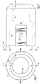
- the numeral 10 designates the mounting assembly which is shown in exploded form in Fig. 3 and in assembled form in Fig. 4.
- the mounting assembly includes a first component which is a barrel 12 comprised of first barrel portion 14, second barrel portion 16, and intermediate barrel portion 18.
- first barrel portion 14 has a diameter greater than that of the intermediate barrel portion 18 which in turn has a diameter greater than the second barrel portion 16.
- the intermediate barrel portion 18 has an eccentric outer surface 19 which will be discussed hereafter.
- the barrel 12 has a longitudinal center axis 20 and the intermediate barrel portion 18 has a center axis 22 which is offset from the center axis 20 as best shown by the dimensional lines "a" and "b" shown in Fig. 3.
- the forward end of intermediate barrel portion 18 has a chamfered or beveled edge 24.
- the barrel 12 has a conventional hole 26 for receiving an anti-rotation pin (not shown). It also has a conventional knob 28 which is adapted to receive the end of the piston of an air cylinder for moving the mounting assembly 10 in a longitudinal direction.
- a flat wrench gripping surface 30 is imposed on opposite sides of the rearward end of barrel 12 to receive an end wrench or the like.
- An indicia mark 32 is imposed on one of the gripping surfaces 30.
- a conventional stuffing tube 34 has a rearward end 36 and a forward end 38.
- a conventional oblong meat emulsion port 40 is located in the side of the stuffing horn to receive meat emulsion.
- a collar 42 has a forward end 44 and a rearward end 46, and a bore 48 extended therethrough.
- Bore 48 is comprised of a rearward eccentric bore portion 50 and a forwardly concentric bore portion 52.
- Bore portion 52 is concentric in that it is centered on the longitudinal center axis 20 of barrel 12.
- Eccentric bore portion 50 has a center or offset axis 54 in that it is offset from center axis 20 as shown by the dimension lines "x" and "y” in Fig. 3.
- the collar 42 has flat wrench gripping surfaces 30A similar to the previously described surfaces 30. It also has an indicia mark 32A on one surface 30A similar to the indicia mark 32 previously described.
- the rearward end 36 of the stuffing tube 34 is slidably mounted on the second barrel portion 16 of the barrel 12. This places the stuffing tube 34 in concentric position on the barrel portion 16 all in alignment with the center longitudinal axis 20 of the barrel.
- the collar 42 is then slidably mounted on the forward end 38 of the stuffing.tube 34 and moved into the position shown in Fig. 4 wherein the rearward end 46 of the collar is moved over the outer surface of the intermediate barrel portion 18.
- the barrel portion 18 has an eccentric outer surface 19, which is received within the eccentric bore portion 50 of the collar 42.
- the collar 42 will only slidably embrace the portion 18 when rotated to a position wherein the eccentricity offset of the surface 19 complements the offset of the eccentric bore portion 50 of the collar. This condition exists only when axis 22 of barrel portion 18 is aligned with axis 54 of bore 50 of collar 42 and both axes 22 and 54 are aligned with axis 20 of barrel 12. This condition is shown in Figs.
- meat emulsion port 40 is also in parallel planar alignment with the surfaces 30 and 30A upon which the indicia marks 32 and 32A appear when the axes 20, 22 and 54 of the barrel 12, the barrel portion 18 and the bore 50, respectively, are aligned.
- this location of the meat emulsion port 40 can also be of use in the assembly of the foregoing components when the collar 42 is placed in position on the stuffing tube before the final tightening step occurs.
- the operator will then take an end wrench or the like and engage the gripping surfaces 30 on the rearward end of the barrel 12.
- a second wrench will be applied to the gripping surfaces 30A on the outer surface of the collar 42.
- the wrench on the collar 42 will then be used to rotate the collar 42 with respect to the barrel 12 to disalign the center axis 22 of the intermediate barrel portion 18 with the eccentric axis 54 of bore portion 50 of the collar.
- This will cause the concentric bore portion 50 of the collar to forcibly bear against the rearward end 36 of the stuffing tube and bind it against the outer surface of the second barrel portion 16 of the barrel 12.
- This operation rigidly connects the stuffing tube 34 to the barrel 12.
- the stuffing tube 34 can be detachably removed from the barrel 12 by rotating the collar 42, with the help of wrenches, in the opposite direction in which the rotation occurred in assembling these components.
- the stuffing tube 34 can be easily and quickly removed from the barrel 12 for cleaning purposes. Also, if the stuffing tube 34 is damaged and must be replaced, it can be thrown away without discarding the barrel 12.
Landscapes
- Life Sciences & Earth Sciences (AREA)
- Engineering & Computer Science (AREA)
- Wood Science & Technology (AREA)
- Zoology (AREA)
- Food Science & Technology (AREA)
- Processing Of Meat And Fish (AREA)
- Containers And Plastic Fillers For Packaging (AREA)
- Coating Apparatus (AREA)
- Protection Of Pipes Against Damage, Friction, And Corrosion (AREA)
Description
Claims (11)
- A stuffing tube mounting assembly, comprising, an elongated cylindrical barrel (12) having a longitudinal center axis and forward and rearward ends, characterised in that it further comprises a first cylindrical barrel portion (14) comprising the rearward end, a second cylindrical barrel portion (16) comprising the forward end, an intermediate cylindrical barrel portion (18) in between the first and second barrel portions, the first and second barrel portions having outer surfaces concentric with the longitudinal center axis (20), the intermediate barrel portion having an outer surface with a center axis (22) parallel to but eccentrically offset from the longitudinal center axis, a hollow elongated stuffing horn (34) having a rearward end detachably telescopically mounted on the second barrel portion (16), a hollow collar (42) having a longitudinal bore extending therethrough comprised of an eccentric bore portion (50) and a concentric bore portion (52), the concentric bore portion extending around and embracing the rearward end (36) of the stuffing tube mounted on the second barrel portion of the barrel (16), the eccentric bore portion (50) having an inner surface with a center axis parallel to but eccentrically offset from the longitudinal axis and rotatably embracing the outer surface of the intermediate barrel portion (18) so that when the collar (42) is rotated in a direction to disalign the center axes of the intermediate barrel portion of the barrel and the eccentric bore portion of the collar, the concentric bore portion (52) of the collar (42) will forcibly bear against the rearward end (36) of the stuffing tube and bind it against the outer surface of the second barrel portion (16) of the barrel.
- The mounting assembly of claim 1 wherein the outer diameter of the first barrel portion is greater than the outer diameter of the intermediate barrel portion.
- The mount assembly of claim 1 wherein the outer diameter of the first barrel portion is greater than the outer diameter of the second barrel portion.
- The mounting assembly of claim 1 wherein the outer diameter of the first barrel portion is greater than the outer diameter of the intermediate and second barrel portions.
- The mounting assembly of claim 4 where the outer diameter of the second barrel portion is less than that of the first and intermediate barrel portions.
- The mounting assembly of claim 2 wherein the intermediate barrel portion has an outer diameter greater than that of the second barrel portion.
- The mounting assembly of claim 1 wherein rotation of the collar in an opposite direction will relieve the rearward end of the stuffing tube from binding engagement with the outer portion of the second barrel portion to permit the stuffing tube to be slidably removed therefrom.
- The mounting assembly of claim 1 wherein the first barrel portion and the collar each have opposite parallel pairs of gripping surfaces to receive gripping wrenches to facilitate the rotation of the collar with respect to the barrel.
- The mounting assembly of claim 8 wherein when the gripping surfaces are in parallel planar alignment, the axes of the eccentric bore portion of the collar and the intermediate barrel portion of the barrel are in alignment with each other and with the longitudinal center axis of the barrel.
- The mounting assembly of claim 9 wherein an indicia mark is located on one each of the gripping surfaces of each of the collar and the intermediate barrel portion to facilitate their movement into a position of parallel planar alignment.
- The mounting assembly of claim 10 wherein a meat emulsion port is located in the stuffing tube in parallel planar alignment with the gripping surfaces bearing the indicia marks when the axes of the eccentric bore portion of the collar and the intermediate barrel portion of the barrel are in alignment with each other and with the longitudinal center axis of the barrel in a manner that the indicia marks and the meat emulsion port are all simultaneously visible to an operator aligning the same.
Applications Claiming Priority (3)
| Application Number | Priority Date | Filing Date | Title |
|---|---|---|---|
| US298028 | 1999-04-22 | ||
| US09/298,028 US6135870A (en) | 1999-04-22 | 1999-04-22 | Mounting assembly for detachably supporting stuffing tubes on sausage encasing machines |
| PCT/US2000/001875 WO2000064266A1 (en) | 1999-04-22 | 2000-01-27 | Mounting assembly for detachably supporting stuffing tubes on sausage encasing machines |
Publications (2)
| Publication Number | Publication Date |
|---|---|
| EP1089631A1 EP1089631A1 (en) | 2001-04-11 |
| EP1089631B1 true EP1089631B1 (en) | 2003-07-30 |
Family
ID=23148700
Family Applications (1)
| Application Number | Title | Priority Date | Filing Date |
|---|---|---|---|
| EP00908373A Expired - Lifetime EP1089631B1 (en) | 1999-04-22 | 2000-01-27 | Mounting assembly for detachably supporting stuffing tubes on sausage encasing machines |
Country Status (12)
| Country | Link |
|---|---|
| US (1) | US6135870A (en) |
| EP (1) | EP1089631B1 (en) |
| JP (1) | JP3333938B1 (en) |
| KR (1) | KR100360071B1 (en) |
| AR (1) | AR022707A1 (en) |
| AT (1) | ATE245904T1 (en) |
| AU (1) | AU743261B2 (en) |
| BR (1) | BR0004309A (en) |
| CA (1) | CA2318265C (en) |
| DE (1) | DE60004147T2 (en) |
| DK (1) | DK1089631T3 (en) |
| WO (1) | WO2000064266A1 (en) |
Families Citing this family (5)
| Publication number | Priority date | Publication date | Assignee | Title |
|---|---|---|---|---|
| US6315653B1 (en) * | 2000-07-14 | 2001-11-13 | Townsend Engineering Company | Mounting assembly for detachably supporting and orienting stuffing tubes on sausage encasing machines |
| US8777702B2 (en) | 2011-07-11 | 2014-07-15 | Marel Meat Processing Inc. | Stuffing tube mounting assembly and follower |
| JP6342437B2 (en) | 2016-02-22 | 2018-06-13 | ゼネラル・エレクトリック・カンパニイ | Radiation tomography system and control program therefor |
| EP4272561A1 (en) * | 2022-05-05 | 2023-11-08 | Poly-clip System GmbH & Co. KG | Production system and coupling unit for producing sausage-shaped products |
| CN115447400A (en) * | 2022-09-21 | 2022-12-09 | 珠海格力电器股份有限公司 | Anti-drag device for driving motor and electric vehicle |
Family Cites Families (9)
| Publication number | Priority date | Publication date | Assignee | Title |
|---|---|---|---|---|
| GB1052955A (en) * | 1900-01-01 | |||
| US888305A (en) * | 1907-04-05 | 1908-05-19 | Nat Specialty Mfg Company | Spout for sausage-stuffers. |
| US2660755A (en) * | 1952-03-04 | 1953-12-01 | Cincinnati Butchers Supply Co | Stuffer valve |
| DE1195630B (en) * | 1960-03-24 | 1965-06-24 | Heinrich Frey | Device for connecting filling pipes to sausage filling machines or the like. |
| US3952370A (en) * | 1972-11-16 | 1976-04-27 | Townsend Engineering Company | Loading tube sleeve for use with an encasing machine |
| US3949446A (en) * | 1974-04-19 | 1976-04-13 | Townsend Engineering Company | Stuffing horn |
| US4569101A (en) * | 1984-12-06 | 1986-02-11 | Geo. A. Hormel & Co. | Dual extrusion apparatus |
| US5013279A (en) * | 1990-03-30 | 1991-05-07 | Johnsonville Sausage, Inc. | Apparatus for encasing a product in a curved casing |
| DE4232759C2 (en) * | 1992-09-27 | 1996-02-22 | Markus Uhl | Device for filling sausage casings of all kinds, in particular made of natural casing, at the exit end of a sausage casing hose gathered into a tubular caterpillar |
-
1999
- 1999-04-22 US US09/298,028 patent/US6135870A/en not_active Expired - Lifetime
-
2000
- 2000-01-27 BR BR0004309-5A patent/BR0004309A/en not_active IP Right Cessation
- 2000-01-27 JP JP2000613269A patent/JP3333938B1/en not_active Expired - Lifetime
- 2000-01-27 DE DE60004147T patent/DE60004147T2/en not_active Expired - Lifetime
- 2000-01-27 EP EP00908373A patent/EP1089631B1/en not_active Expired - Lifetime
- 2000-01-27 WO PCT/US2000/001875 patent/WO2000064266A1/en not_active Ceased
- 2000-01-27 DK DK00908373T patent/DK1089631T3/en active
- 2000-01-27 AU AU29730/00A patent/AU743261B2/en not_active Ceased
- 2000-01-27 AT AT00908373T patent/ATE245904T1/en not_active IP Right Cessation
- 2000-01-27 CA CA002318265A patent/CA2318265C/en not_active Expired - Fee Related
- 2000-01-27 KR KR1020007014677A patent/KR100360071B1/en not_active Expired - Fee Related
- 2000-02-21 AR ARP000100729A patent/AR022707A1/en active IP Right Grant
Also Published As
| Publication number | Publication date |
|---|---|
| ATE245904T1 (en) | 2003-08-15 |
| CA2318265C (en) | 2003-04-08 |
| KR100360071B1 (en) | 2002-11-07 |
| KR20010043993A (en) | 2001-05-25 |
| EP1089631A1 (en) | 2001-04-11 |
| BR0004309A (en) | 2001-10-30 |
| AU743261B2 (en) | 2002-01-24 |
| US6135870A (en) | 2000-10-24 |
| JP3333938B1 (en) | 2002-10-15 |
| AU2973000A (en) | 2000-11-10 |
| DK1089631T3 (en) | 2003-11-24 |
| WO2000064266A1 (en) | 2000-11-02 |
| AR022707A1 (en) | 2002-09-04 |
| JP2002541869A (en) | 2002-12-10 |
| DE60004147D1 (en) | 2003-09-04 |
| CA2318265A1 (en) | 2000-10-22 |
| DE60004147T2 (en) | 2004-03-11 |
Similar Documents
| Publication | Publication Date | Title |
|---|---|---|
| US5778511A (en) | Swing apparatus and method | |
| US4899611A (en) | Device for the correct positioning of the lower steering shaft on the steering-box pinion and on the upper shaft | |
| EP0300119A1 (en) | A head connecting device in golf clubs | |
| US4639240A (en) | Chainguard | |
| US6135870A (en) | Mounting assembly for detachably supporting stuffing tubes on sausage encasing machines | |
| WO2000067925A1 (en) | Tube cutter/cleaner attachment | |
| US20030177581A1 (en) | Manual stretcher | |
| US6227810B1 (en) | Bicycle air pump structure | |
| MXPA00009502A (en) | Mounting assembly for detachably supporting stuffing tubes on sausage encasing machines | |
| CA2415390C (en) | Mounting assembly for detachably supporting and orienting stuffing tubes on sausage encasing machines | |
| US6148492A (en) | Extractor for arrowheads | |
| US7013772B1 (en) | Method and apparatus for arrow shaft truing | |
| AU2001263135A1 (en) | Mounting assembly for detachably supporting and orienting stuffing tubes on sausage encasing machines | |
| JP2003040180A (en) | Motorcycle and its triple tree | |
| US6352128B1 (en) | Steered-head ram drilling tool | |
| JP3590895B2 (en) | Air chuck | |
| JPH0650649Y2 (en) | Drive shaft | |
| FI75906C (en) | Drilling rig control | |
| EP1099503A3 (en) | A saw blade clamp device for an electric reciprocating saw | |
| LU85114A1 (en) | MARKING DEVICE SUCH AS AN ANTI-THEFT MARKING GUN | |
| JPH10248446A (en) | A structure for attaching a front pole to a main pole and a connecting rod provided with the same | |
| FR2874345A1 (en) | Metallic rings assembling device for instrument panel of vehicle, has lever pushed by user in order to move cone so that fingers leave from their housing and ring is pressed on edge of housing of instrument panel | |
| JPS59167611U (en) | Work clamp device | |
| FR2803796A1 (en) | Mounting of print head in thermal printer, uses clip fastening to side plates that run along printing bar to position head |
Legal Events
| Date | Code | Title | Description |
|---|---|---|---|
| PUAI | Public reference made under article 153(3) epc to a published international application that has entered the european phase |
Free format text: ORIGINAL CODE: 0009012 |
|
| 17P | Request for examination filed |
Effective date: 20000710 |
|
| AK | Designated contracting states |
Kind code of ref document: A1 Designated state(s): AT BE CH CY DE DK ES FI FR GB GR IE IT LI LU MC NL PT SE |
|
| GRAH | Despatch of communication of intention to grant a patent |
Free format text: ORIGINAL CODE: EPIDOS IGRA |
|
| GRAH | Despatch of communication of intention to grant a patent |
Free format text: ORIGINAL CODE: EPIDOS IGRA |
|
| GRAA | (expected) grant |
Free format text: ORIGINAL CODE: 0009210 |
|
| AK | Designated contracting states |
Designated state(s): AT BE CH CY DE DK ES FI FR GB GR IE IT LI LU MC NL PT SE |
|
| PG25 | Lapsed in a contracting state [announced via postgrant information from national office to epo] |
Ref country code: CH Free format text: LAPSE BECAUSE OF FAILURE TO SUBMIT A TRANSLATION OF THE DESCRIPTION OR TO PAY THE FEE WITHIN THE PRESCRIBED TIME-LIMIT Effective date: 20030730 Ref country code: FI Free format text: LAPSE BECAUSE OF FAILURE TO SUBMIT A TRANSLATION OF THE DESCRIPTION OR TO PAY THE FEE WITHIN THE PRESCRIBED TIME-LIMIT Effective date: 20030730 Ref country code: BE Free format text: LAPSE BECAUSE OF FAILURE TO SUBMIT A TRANSLATION OF THE DESCRIPTION OR TO PAY THE FEE WITHIN THE PRESCRIBED TIME-LIMIT Effective date: 20030730 Ref country code: AT Free format text: LAPSE BECAUSE OF FAILURE TO SUBMIT A TRANSLATION OF THE DESCRIPTION OR TO PAY THE FEE WITHIN THE PRESCRIBED TIME-LIMIT Effective date: 20030730 Ref country code: LI Free format text: LAPSE BECAUSE OF FAILURE TO SUBMIT A TRANSLATION OF THE DESCRIPTION OR TO PAY THE FEE WITHIN THE PRESCRIBED TIME-LIMIT Effective date: 20030730 Ref country code: CY Free format text: LAPSE BECAUSE OF FAILURE TO SUBMIT A TRANSLATION OF THE DESCRIPTION OR TO PAY THE FEE WITHIN THE PRESCRIBED TIME-LIMIT Effective date: 20030730 |
|
| REG | Reference to a national code |
Ref country code: GB Ref legal event code: FG4D |
|
| REG | Reference to a national code |
Ref country code: CH Ref legal event code: EP |
|
| REG | Reference to a national code |
Ref country code: IE Ref legal event code: FG4D |
|
| REF | Corresponds to: |
Ref document number: 60004147 Country of ref document: DE Date of ref document: 20030904 Kind code of ref document: P |
|
| PG25 | Lapsed in a contracting state [announced via postgrant information from national office to epo] |
Ref country code: SE Free format text: LAPSE BECAUSE OF FAILURE TO SUBMIT A TRANSLATION OF THE DESCRIPTION OR TO PAY THE FEE WITHIN THE PRESCRIBED TIME-LIMIT Effective date: 20031030 Ref country code: GR Free format text: LAPSE BECAUSE OF FAILURE TO SUBMIT A TRANSLATION OF THE DESCRIPTION OR TO PAY THE FEE WITHIN THE PRESCRIBED TIME-LIMIT Effective date: 20031030 |
|
| PG25 | Lapsed in a contracting state [announced via postgrant information from national office to epo] |
Ref country code: ES Free format text: LAPSE BECAUSE OF FAILURE TO SUBMIT A TRANSLATION OF THE DESCRIPTION OR TO PAY THE FEE WITHIN THE PRESCRIBED TIME-LIMIT Effective date: 20031110 |
|
| REG | Reference to a national code |
Ref country code: DK Ref legal event code: T3 |
|
| PG25 | Lapsed in a contracting state [announced via postgrant information from national office to epo] |
Ref country code: PT Free format text: LAPSE BECAUSE OF FAILURE TO SUBMIT A TRANSLATION OF THE DESCRIPTION OR TO PAY THE FEE WITHIN THE PRESCRIBED TIME-LIMIT Effective date: 20031230 |
|
| ET | Fr: translation filed | ||
| PG25 | Lapsed in a contracting state [announced via postgrant information from national office to epo] |
Ref country code: GB Free format text: LAPSE BECAUSE OF NON-PAYMENT OF DUE FEES Effective date: 20040127 Ref country code: IE Free format text: LAPSE BECAUSE OF NON-PAYMENT OF DUE FEES Effective date: 20040127 Ref country code: LU Free format text: LAPSE BECAUSE OF NON-PAYMENT OF DUE FEES Effective date: 20040127 |
|
| PG25 | Lapsed in a contracting state [announced via postgrant information from national office to epo] |
Ref country code: MC Free format text: LAPSE BECAUSE OF NON-PAYMENT OF DUE FEES Effective date: 20040131 |
|
| REG | Reference to a national code |
Ref country code: CH Ref legal event code: PL |
|
| PLBE | No opposition filed within time limit |
Free format text: ORIGINAL CODE: 0009261 |
|
| STAA | Information on the status of an ep patent application or granted ep patent |
Free format text: STATUS: NO OPPOSITION FILED WITHIN TIME LIMIT |
|
| 26N | No opposition filed |
Effective date: 20040504 |
|
| GBPC | Gb: european patent ceased through non-payment of renewal fee |
Effective date: 20040127 |
|
| REG | Reference to a national code |
Ref country code: IE Ref legal event code: MM4A |
|
| REG | Reference to a national code |
Ref country code: FR Ref legal event code: PLFP Year of fee payment: 17 |
|
| REG | Reference to a national code |
Ref country code: FR Ref legal event code: PLFP Year of fee payment: 18 |
|
| REG | Reference to a national code |
Ref country code: FR Ref legal event code: PLFP Year of fee payment: 19 |
|
| REG | Reference to a national code |
Ref country code: FR Ref legal event code: PLFP Year of fee payment: 20 |
|
| PGFP | Annual fee paid to national office [announced via postgrant information from national office to epo] |
Ref country code: FR Payment date: 20180326 Year of fee payment: 20 |
|
| PGFP | Annual fee paid to national office [announced via postgrant information from national office to epo] |
Ref country code: DE Payment date: 20190129 Year of fee payment: 20 Ref country code: FR Payment date: 20190125 Year of fee payment: 20 Ref country code: IT Payment date: 20190121 Year of fee payment: 20 Ref country code: NL Payment date: 20190126 Year of fee payment: 20 |
|
| PGFP | Annual fee paid to national office [announced via postgrant information from national office to epo] |
Ref country code: DK Payment date: 20190129 Year of fee payment: 20 |
|
| REG | Reference to a national code |
Ref country code: DE Ref legal event code: R071 Ref document number: 60004147 Country of ref document: DE |
|
| REG | Reference to a national code |
Ref country code: NL Ref legal event code: MK Effective date: 20200126 |
|
| REG | Reference to a national code |
Ref country code: DK Ref legal event code: EUP Effective date: 20200127 |