EP1089538A1 - A system to provide lifeline IP telephony service on cable access networks - Google Patents
A system to provide lifeline IP telephony service on cable access networks Download PDFInfo
- Publication number
- EP1089538A1 EP1089538A1 EP00120187A EP00120187A EP1089538A1 EP 1089538 A1 EP1089538 A1 EP 1089538A1 EP 00120187 A EP00120187 A EP 00120187A EP 00120187 A EP00120187 A EP 00120187A EP 1089538 A1 EP1089538 A1 EP 1089538A1
- Authority
- EP
- European Patent Office
- Prior art keywords
- cable
- circuits
- power
- modem
- trunk amplifier
- Prior art date
- Legal status (The legal status is an assumption and is not a legal conclusion. Google has not performed a legal analysis and makes no representation as to the accuracy of the status listed.)
- Withdrawn
Links
Images

Classifications
-
- H—ELECTRICITY
- H04—ELECTRIC COMMUNICATION TECHNIQUE
- H04M—TELEPHONIC COMMUNICATION
- H04M19/00—Current supply arrangements for telephone systems
- H04M19/08—Current supply arrangements for telephone systems with current supply sources at the substations
Definitions
- the invention disclosed is broadly related to telecommunications and is more particularly related to systems and methods to provide telephony for cable access networks.
- Broadband access networks e.g., hybrid fiber/coaxial
- HFC hybrid fiber/coaxial
- Local telephone networks are designed to meet an unavailability objective of 53 minutes/year/line.
- HFC cable networks have a downtime of 622 minutes/year/line due to AC power failure and additional 125 minutes/year/line due to failures other than AC power failure (e.g., amplifier failure, water leakage, cable cuts).
- AC power failure e.g., amplifier failure, water leakage, cable cuts.
- One key difference between a local loop network and an HFC cable network is that the former uses battery power at the central office. The latter requires commercial AC power in the field for amplifiers and coaxial taps and at the subscriber's location for the cable modem and the telephone set. Loss of AC power causes a failure of the HFC cable delivery network and the subscriber's modem and telephone.
- a communications network topology is disclosed that provides uniterruptible telephone services on cable access networks.
- a hybrid fiber/coaxial cable connected to a headend or distribution hub provides connectivity for many cable data modems and set top boxes in a neighborhood or community, in the conventional manner.
- the invention prevents the HFC cable delivery network and the subscriber's modem and telephone from failing.
- a cable access network includes a cable trunk amplifier, connected over a coaxial cable to a plurality of cable data modems, to provide backup power to the cable modems during power outages experienced by either the trunk amplifier or the modems, thereby insuring uninterruptible IP telephone service.
- the trunk amplifier applies a DC voltage across the conductors of the coaxial cable.
- An AC/DC power converter and regulator and also a backup battery are sources of power for the DC voltage applied to the coaxial cable.
- a power outage sensor selectively connects either the AC/DC power converter and regulator or, alternately, the backup battery to the cable, depending on whether there is an outage sensed at the trunk amplifier.
- each cable data modem connected to the trunk amplifier is partitioned into IP voice circuits and other circuits not contributing to the IP voice function.
- the other circuits include, for example, video/audio receiver circuits and IP data transceiver circuits.
- the IP voice circuits are connected to the subscriber's telephone hand set.
- the cable data modem applies a DC voltage to the IP voice circuits and the subscriber's telephone hand set.
- An AC/DC power converter and regulator in the modem and also the DC voltage from the coaxial cable are sources of power for the DC voltage applied to the IP voice circuits.
- a power outage sensor selectively connects the IP voice circuits to either the AC/DC power converter and regulator in the modem or, alternately, the DC voltage from the coaxial cable, depending on whether there is an outage sensed at the cable data modem.
- the other circuits such as the video/audio receiver circuits and IP data transceiver circuits are powered only by the AC/DC power converter and regulator in the cable data modem. In this manner, if there is a general power outage affecting both the trunk amplifier and many of the cable data modems connected to it, the power to be supplied by the backup battery at the trunk amplifier is only required to power the IP voice circuits and the subscriber's telephone hand set.
- the invention is a cost-effective solution to providing uninterruptible telephone service on an HFC cable network, in the face of power outages anywhere from the cable network headend to the subscriber's telephone.
- the communications network topology is shown in the network diagram of FIG. 1.
- the headend or distribution hub 110 is connected to an Internet Protocol Network which can be either a wide area network or a local area network 100.
- the external network 100 can have a network layer such as IP, IPX, X.25, or AppleTalk on top of an appropriate link layer or it can solely have a link layer such as Ethernet, ATM, FDDI, token ring, IEEE 802.3, or IEEE 802.12. It is also connected to a telephone network which can either be the public switched telephone network or a private telephone network 102. It is also connected to a source of video channels and FM audio channels 104.
- Two standards for the transmission of data over cable networks are: (1) The IEEE 802.14 Cable-TV Access Method and Physical Layer Specification; and (2) The ITU Standard J112 Data over Cable Service Interface Specification (DOCSIS). These standards define modulation and protocols for high-speed bi-directional data transmissions over cable.
- DOCSIS The ITU Standard J112 Data over Cable Service Interface Specification
- the headend or distribution hub 110 functions to distribute these signals over the hybrid fiber/coaxial cable (HFC) network to cable data modems (CDM) connected to respective coaxial cable distribution paths in the network.
- the hybrid fiber/coax cable network shown in FIG. 1 extends to the modems CDM, and includes the headend as well as the cables.
- Each hybrid fiber/coaxial cable, for example HFC(0) includes an optical fiber component connected to the headend 110 which goes through the fiber node FN(0) optical to electrical transducer and through an interface 106 into the coaxial cable distribution portion of the network which consists of a trunk amplifier AMP(0), for example, which delivers over coaxial cable C(0), for example, the electrical analog of the optical signals in the optical fiber portion of the cable.
- the electrical signals are exchanged with respective cable data modems, CDM(002), for example, as shown in FIG. 1.
- Cable data modem CDM(002) for example, is shown connected to a conventional telephone hand set P(002).
- the hybrid fiber/coaxial cable connected to the headend 110 provides connectivity for many cable data modems in a neighborhood or community, in the conventional manner.
- the trunk amplifier AMP(0) for example, has a backup battery B(0), for example, which can be a lead-acid battery, a solar cell battery, a fuel cell battery, or the like.
- the battery B(0) must be able to supply sufficient backup power during a power outage at the trunk amplifier to deliver DC power to those IP voice circuits in use during the outage.
- the average DC power consumption of the IP voice circuits in one cable data modem be 10 watts. Further, let there be 100 cable data modems connected to the trunk amplifier. Still further, let there be no more than 25 telephone subscribers that need to use their telephone during a power outage. Then, the electrical power required from the backup battery at the trunk amplifier is 250 watts. A conventional 105 amp-hour lead-acid battery can deliver a sufficient amount of backup power for a period of five hours, for this example.
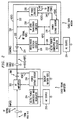
- FIG. 2 is a functional block diagram of the cable trunk amplifier and the cable data modem, in accordance with the invention.
- the cable access network includes the cable trunk amplifier AMP(0), connected over the coaxial cable C(0) to a plurality of cable data modems including modem CDM(002), to provide backup power to the cable modems during power outages experienced by either the trunk amplifier or the modems, thereby insuring uninterruptible IP telephone service.
- Cable data modem CDM(002) is connected to a conventional telephone hand set P(002), which also derives its power from the modem.
- the trunk amplifier AMP(0) applies a DC voltage V(DC) across the conductors of the coaxial cable C(0).
- An AC/DC power converter and regulator 204 connected to AC source 210 and also a backup battery B(0) are sources of power for the DC voltage V(DC) applied to the coaxial cable C(0).
- a power outage sensor 206 selectively connects either the AC/DC power converter and regulator 204 or, alternately, the backup battery B(0) to the cable C(0), depending on whether there is an outage sensed at the trunk amplifier AMP(0).
- the RF amplifier 202 in the trunk amplifier AMP(0) amplifies the RF signal V(RF) from the headend, which is coupled across the line capacitor 208 to the coaxial cable C(0) connected to the cable modem CDM(002).
- the resulting voltage signal on the cable C(0) is the sum V(DC) + V(RF), which is provided to the cable data modem CDM(002).
- each cable data modem CDM(002) connected to the trunk amplifier AMP(0) is partitioned into IP voice circuits 230 and other circuits not contributing to the IP voice function.
- the other circuits include, for example, video/audio receiver circuits 226 and IP data transceiver circuits 228.
- the IP voice circuits 230 are connected to the subscriber's telephone hand set P(002) on line 242.
- the cable data modem CMD(002) applies a DC voltage V(DC)' to the IP voice circuits 230 and the subscriber's telephone hand set P(002).
- the line capacitor 224 couples the RF signal V(RF) signal from the cable C(0) to line 222 to the video/audio receiver circuits 226, the IP data transceiver circuits 228, and the IP voice circuits 230.
- the line 220 provides the V(DC) voltage from the cable C(0) over line 220 to power outage sensor 236 for the IP voice circuits 230.
- An AC/DC power converter and regulator 232 in the modem CDM(002) supplied by AC source 234 and also the DC voltage V(DC) from the coaxial cable C(0) are sources of power for the DC voltage V(DC)' applied to the IP voice circuits 230.
- the power outage sensor 236 selectively connects the IP voice circuits 230 to either the AC/DC power converter and regulator 232 over line 238 in the modem CDM(002) or, alternately, the DC voltage V(DC) from the coaxial cable C(0) over line 240, depending on whether there is an outage sensed at the cable data modem CDM(002).
- the other circuits such as the video/audio receiver circuits 226 and IP data transceiver circuits 228 are powered only by the AC/DC power converter and regulator 232 voltage V(PS) in-the cable data modem CDM(002).
- the power to be supplied by the backup battery B(0) at the trunk amplifier is only required to power the IP voice circuits 230 and the subscriber's telephone hand set P(002).
- the invention is a cost-effective solution to providing uninterruptible telephone service on an HFC cable network, in the face of power outages anywhere from the cable network headend to the subscriber's telephone.
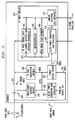
- FIG. 3 is a more detailed functional block diagram of the cable data modem, in accordance with the invention.
- the figure shows the details of the IP voice circuits 230, which include the DC/DC power converter and regulator 302 that receives the voltage V(DC)' over line 240 from the power outage sensor 236.
- the DC/DC power converter and regulator 302 supplies DC voltage to the ROM, DRAM, Flash memory 304, the microcontroller 306, the IP voice digital CATV RF channel receiver and upstream transmitter 308 over line 310.
- the DC/DC power converter and regulator 302 also supplies DC voltage to the analog telephone RJ11 interface 312 that connects over line 242 to the telephone hand set P(002).
- Bus 314 distributes voice signals between the ROM, DRAM, Flash memory 304, the microcontroller 306, the IF voice digital CATV RF channel receiver and upstream transmitter 308, and the analog telephone RJ11 interface 312.
- V(PS) voltage level is high enough so that a diode voltage drop will still provide a solid power supply voltage V(DC) to the system, which is usually true if the V(PS) is 5 V (plus or minus 10 percent).
- V(PS) being 3 V (plus or minus 5 percent) for powering an integrated circuit
- using the method of the Inglis et al. Figure 8 results in a voltage range of only 2.2 V to 2.5 V (i.e., V(PS) minus the diode voltage drop). This level of power supply voltage (2.2 V to 2.5 V) may degrade the performance of a logic circuit to a point which is not acceptable.
- Inglis et al. disclose another power supply loss sensor in greater detail.
- the second Power Supply Loss Sensor circuit shown in the Inglis et al. Figures 1 - 7 detects the loss of a power supply voltage in a system that includes a primary and a backup power supply.
- One or both of the power sources are typically batteries; for example, a rechargeable battery may be the primary power source, and a long-life battery (e.g., lithium or alkaline) may be the backup, with other power sources being possible.
- the loss sensor detects a gradual degradation or total loss of V(PS), the primary power supply to the system.
- Either the primary power supply or the backup power supply can be removed from the system at any time and the circuit will maintain power to a selected portion of a system, using the remaining power supply.
- the loss sensor circuit is designed with all-digital logic or equivalent low power components, thus minimizing power dissipation and increasing its versatility. That is, this circuit can be fabricated with either a digital or analog integrated circuit fabrication process.
- the invention is a cost-effective solution to providing uninterruptible telephone service on an HFC cable network, in the face of power outages anywhere from the cable network headend to the subscriber's telephone.
Landscapes
- Engineering & Computer Science (AREA)
- Signal Processing (AREA)
- Telephonic Communication Services (AREA)
- Monitoring And Testing Of Transmission In General (AREA)
- Two-Way Televisions, Distribution Of Moving Picture Or The Like (AREA)
Abstract
A cable access network includes a cable trunk amplifier connected over a coaxial
cable to A plurality of cable data modems to provide backup power to the cable modem
during power outages experienced by either the trunk amplifier or the modems, thereby
insuring uninterruptible IP telephone service. The trunk amplifier applies a DC voltage
across the conductors of the coaxial cable. An AC/DC power converter and regulator and
also a backup battery are sources of power for the DC voltage applied to the coaxial
cable. A power outage sensor selectively connects either the AC/DC power converter and
regulator or, alternately, the backup battery to the cable, depending on whether there is an
outage sensed at the trunk amplifier. Each cable data modem connected to the trunk
amplifier is partitioned into IP voice circuits and other circuits not contributing to the IP
voice function. The other circuits include, for example, video/audio receiver circuits and
IP data transceiver circuits. The IP voice circuits are connected to the subscriber's
telephone hand set. The cable data modem applies a DC voltage to the IP voice circuits
and the subscriber's telephone hand set. An AC/DC power converter and regulator in the
modem and also the DC voltage from the coaxial cable are sources of power for the DC
voltage applied to the IP voice circuits. A power outage sensor selectively connects the
IP voice circuits to either the AC/DC power converter and regulator in the modem or,
alternately, the DC voltage from the coaxial cable, depending on whether there is an
outage sensed at the cable data modem. The other circuits such as the video/audio
receiver circuits and IP data transceiver circuits are powered only by the AC/DC power
converter and regulator in the cable data modem. In this manner, if there is a general
power outage affecting both the trunk amplifier and many of the cable data modems
connected to it, the power to be supplied by the backup battery at the trunk amplifier is
only required to power the IP voice circuits and the subscriber's telephone hand set.
Description
- The invention disclosed is broadly related to telecommunications and is more particularly related to systems and methods to provide telephony for cable access networks.
- Broadband access networks (e.g., hybrid fiber/coaxial) are used to provide television programming and Internet access for customers. More recently they are being investigated to provide IP telephony service. However, the reliability of hybrid fiber/coaxial (HFC) cable networks is not comparable to the high reliability of the local telephone network. Local telephone networks are designed to meet an unavailability objective of 53 minutes/year/line. HFC cable networks have a downtime of 622 minutes/year/line due to AC power failure and additional 125 minutes/year/line due to failures other than AC power failure (e.g., amplifier failure, water leakage, cable cuts). One key difference between a local loop network and an HFC cable network is that the former uses battery power at the central office. The latter requires commercial AC power in the field for amplifiers and coaxial taps and at the subscriber's location for the cable modem and the telephone set. Loss of AC power causes a failure of the HFC cable delivery network and the subscriber's modem and telephone.
- What is needed is a cost-effective approach to provide uninterruptible telephone service on an HFC cable network in the face of power outages anywhere from the cable network headend to the subscriber's telephone.
- A communications network topology is disclosed that provides uniterruptible telephone services on cable access networks. A hybrid fiber/coaxial cable connected to a headend or distribution hub provides connectivity for many cable data modems and set top boxes in a neighborhood or community, in the conventional manner. When there is a power failure, the invention prevents the HFC cable delivery network and the subscriber's modem and telephone from failing.
- In accordance with the invention, a cable access network includes a cable trunk amplifier, connected over a coaxial cable to a plurality of cable data modems, to provide backup power to the cable modems during power outages experienced by either the trunk amplifier or the modems, thereby insuring uninterruptible IP telephone service. The trunk amplifier applies a DC voltage across the conductors of the coaxial cable. An AC/DC power converter and regulator and also a backup battery are sources of power for the DC voltage applied to the coaxial cable. A power outage sensor selectively connects either the AC/DC power converter and regulator or, alternately, the backup battery to the cable, depending on whether there is an outage sensed at the trunk amplifier. In accordance with the invention, each cable data modem connected to the trunk amplifier is partitioned into IP voice circuits and other circuits not contributing to the IP voice function. The other circuits include, for example, video/audio receiver circuits and IP data transceiver circuits. The IP voice circuits are connected to the subscriber's telephone hand set. The cable data modem applies a DC voltage to the IP voice circuits and the subscriber's telephone hand set. An AC/DC power converter and regulator in the modem and also the DC voltage from the coaxial cable are sources of power for the DC voltage applied to the IP voice circuits. A power outage sensor selectively connects the IP voice circuits to either the AC/DC power converter and regulator in the modem or, alternately, the DC voltage from the coaxial cable, depending on whether there is an outage sensed at the cable data modem. The other circuits such as the video/audio receiver circuits and IP data transceiver circuits are powered only by the AC/DC power converter and regulator in the cable data modem. In this manner, if there is a general power outage affecting both the trunk amplifier and many of the cable data modems connected to it, the power to be supplied by the backup battery at the trunk amplifier is only required to power the IP voice circuits and the subscriber's telephone hand set. The invention is a cost-effective solution to providing uninterruptible telephone service on an HFC cable network, in the face of power outages anywhere from the cable network headend to the subscriber's telephone.
-
- Figure 1 is an overall network diagram of a cable access network, in accordance with the invention.
- Figure 2 is a functional block diagram of the cable trunk amplifier and the cable data modem, in accordance with the invention.
- Figure 3 is a more detailed functional block diagram of the cable data modem, in accordance with the invention.
-
- The communications network topology, in accordance with the invention, is shown in the network diagram of FIG. 1. The headend or
distribution hub 110 is connected to an Internet Protocol Network which can be either a wide area network or alocal area network 100. Theexternal network 100 can have a network layer such as IP, IPX, X.25, or AppleTalk on top of an appropriate link layer or it can solely have a link layer such as Ethernet, ATM, FDDI, token ring, IEEE 802.3, or IEEE 802.12. It is also connected to a telephone network which can either be the public switched telephone network or aprivate telephone network 102. It is also connected to a source of video channels andFM audio channels 104. Two standards for the transmission of data over cable networks are: (1) The IEEE 802.14 Cable-TV Access Method and Physical Layer Specification; and (2) The ITU Standard J112 Data over Cable Service Interface Specification (DOCSIS). These standards define modulation and protocols for high-speed bi-directional data transmissions over cable. - The headend or
distribution hub 110 functions to distribute these signals over the hybrid fiber/coaxial cable (HFC) network to cable data modems (CDM) connected to respective coaxial cable distribution paths in the network. The hybrid fiber/coax cable network shown in FIG. 1 extends to the modems CDM, and includes the headend as well as the cables. Each hybrid fiber/coaxial cable, for example HFC(0), includes an optical fiber component connected to theheadend 110 which goes through the fiber node FN(0) optical to electrical transducer and through aninterface 106 into the coaxial cable distribution portion of the network which consists of a trunk amplifier AMP(0), for example, which delivers over coaxial cable C(0), for example, the electrical analog of the optical signals in the optical fiber portion of the cable. The electrical signals are exchanged with respective cable data modems, CDM(002), for example, as shown in FIG. 1. Cable data modem CDM(002), for example, is shown connected to a conventional telephone hand set P(002). The hybrid fiber/coaxial cable connected to theheadend 110 provides connectivity for many cable data modems in a neighborhood or community, in the conventional manner. The trunk amplifier AMP(0), for example, has a backup battery B(0), for example, which can be a lead-acid battery, a solar cell battery, a fuel cell battery, or the like. The battery B(0) must be able to supply sufficient backup power during a power outage at the trunk amplifier to deliver DC power to those IP voice circuits in use during the outage. For example, let the average DC power consumption of the IP voice circuits in one cable data modem be 10 watts. Further, let there be 100 cable data modems connected to the trunk amplifier. Still further, let there be no more than 25 telephone subscribers that need to use their telephone during a power outage. Then, the electrical power required from the backup battery at the trunk amplifier is 250 watts. A conventional 105 amp-hour lead-acid battery can deliver a sufficient amount of backup power for a period of five hours, for this example. - When a cable's connection to the
headend 110 is accidentally interrupted--for example, by the loss of electrical power to the amplifier AMP(0) or to the cable data modems CDM(002)-- service can be rapidly restored to the affected cable data modems attached to the cable, by means of the invention disclosed herein. - Figure 2 is a functional block diagram of the cable trunk amplifier and the cable data modem, in accordance with the invention. In accordance with the invention, the cable access network includes the cable trunk amplifier AMP(0), connected over the coaxial cable C(0) to a plurality of cable data modems including modem CDM(002), to provide backup power to the cable modems during power outages experienced by either the trunk amplifier or the modems, thereby insuring uninterruptible IP telephone service. Cable data modem CDM(002) is connected to a conventional telephone hand set P(002), which also derives its power from the modem.
- The trunk amplifier AMP(0) applies a DC voltage V(DC) across the conductors of the coaxial cable C(0). An AC/DC power converter and
regulator 204 connected toAC source 210 and also a backup battery B(0) are sources of power for the DC voltage V(DC) applied to the coaxial cable C(0). Apower outage sensor 206 selectively connects either the AC/DC power converter andregulator 204 or, alternately, the backup battery B(0) to the cable C(0), depending on whether there is an outage sensed at the trunk amplifier AMP(0). TheRF amplifier 202 in the trunk amplifier AMP(0) amplifies the RF signal V(RF) from the headend, which is coupled across theline capacitor 208 to the coaxial cable C(0) connected to the cable modem CDM(002). The resulting voltage signal on the cable C(0) is the sum V(DC) + V(RF), which is provided to the cable data modem CDM(002). - In accordance with the invention, each cable data modem CDM(002) connected to the trunk amplifier AMP(0) is partitioned into
IP voice circuits 230 and other circuits not contributing to the IP voice function. The other circuits include, for example, video/audio receiver circuits 226 and IPdata transceiver circuits 228. TheIP voice circuits 230 are connected to the subscriber's telephone hand set P(002) online 242. The cable data modem CMD(002) applies a DC voltage V(DC)' to theIP voice circuits 230 and the subscriber's telephone hand set P(002). The line capacitor 224 couples the RF signal V(RF) signal from the cable C(0) toline 222 to the video/audio receiver circuits 226, the IPdata transceiver circuits 228, and theIP voice circuits 230. Theline 220 provides the V(DC) voltage from the cable C(0) overline 220 topower outage sensor 236 for theIP voice circuits 230. An AC/DC power converter andregulator 232 in the modem CDM(002) supplied byAC source 234 and also the DC voltage V(DC) from the coaxial cable C(0) are sources of power for the DC voltage V(DC)' applied to theIP voice circuits 230. Thepower outage sensor 236 selectively connects theIP voice circuits 230 to either the AC/DC power converter andregulator 232 overline 238 in the modem CDM(002) or, alternately, the DC voltage V(DC) from the coaxial cable C(0) overline 240, depending on whether there is an outage sensed at the cable data modem CDM(002). The other circuits such as the video/audio receiver circuits 226 and IPdata transceiver circuits 228 are powered only by the AC/DC power converter andregulator 232 voltage V(PS) in-the cable data modem CDM(002). In this manner, if there is a general power outage affecting both the trunk amplifier AMP(0) and many of the cable data modems connected to it, the power to be supplied by the backup battery B(0) at the trunk amplifier is only required to power theIP voice circuits 230 and the subscriber's telephone hand set P(002). The invention is a cost-effective solution to providing uninterruptible telephone service on an HFC cable network, in the face of power outages anywhere from the cable network headend to the subscriber's telephone. - Figure 3 is a more detailed functional block diagram of the cable data modem, in accordance with the invention. The figure shows the details of the
IP voice circuits 230, which include the DC/DC power converter andregulator 302 that receives the voltage V(DC)' overline 240 from thepower outage sensor 236. The DC/DC power converter andregulator 302 supplies DC voltage to the ROM, DRAM,Flash memory 304, themicrocontroller 306, the IP voice digital CATV RF channel receiver andupstream transmitter 308 overline 310. The DC/DC power converter andregulator 302 also supplies DC voltage to the analogtelephone RJ11 interface 312 that connects overline 242 to the telephone hand set P(002). Bus 314 distributes voice signals between the ROM, DRAM,Flash memory 304, themicrocontroller 306, the IF voice digital CATV RF channel receiver andupstream transmitter 308, and the analogtelephone RJ11 interface 312. - Two examples of the
power outage sensor 206 in the trunk amplifier AMP(0) and thepower outage sensor 236 in the cable data modem CDM(002) are given in the above-referenced US Patent 5,457,414 entitled "Power Supply Loss Sensor" by David A. Inglis and Hyun Lee, assigned to the AT&T CORP and incorporated herein by reference. In Figure 8 of Inglis, et al., data corruption or system malfunction due to loss of the primary DC power supply is commonly prevented by using a "diode-switch" method. The Inglis et al. Figure 8 shows two diodes external to the system device (e.g., an integrated circuit), and connected so that one diode is reverse biased while the other diode is forward biased. This type of solution is acceptable if the V(PS) voltage level is high enough so that a diode voltage drop will still provide a solid power supply voltage V(DC) to the system, which is usually true if the V(PS) is 5 V (plus or minus 10 percent). However, in the case of V(PS) being 3 V (plus or minus 5 percent) for powering an integrated circuit, using the method of the Inglis et al. Figure 8 results in a voltage range of only 2.2 V to 2.5 V (i.e., V(PS) minus the diode voltage drop). This level of power supply voltage (2.2 V to 2.5 V) may degrade the performance of a logic circuit to a point which is not acceptable. For example, the speed degradation due to the lowering of the power supply from 3 V to 2.2 V is typically a factor of 2. Inglis et al. disclose another power supply loss sensor in greater detail. The second Power Supply Loss Sensor circuit shown in the Inglis et al. Figures 1 - 7 detects the loss of a power supply voltage in a system that includes a primary and a backup power supply. One or both of the power sources are typically batteries; for example, a rechargeable battery may be the primary power source, and a long-life battery (e.g., lithium or alkaline) may be the backup, with other power sources being possible. The loss sensor detects a gradual degradation or total loss of V(PS), the primary power supply to the system. Either the primary power supply or the backup power supply can be removed from the system at any time and the circuit will maintain power to a selected portion of a system, using the remaining power supply. The loss sensor circuit is designed with all-digital logic or equivalent low power components, thus minimizing power dissipation and increasing its versatility. That is, this circuit can be fabricated with either a digital or analog integrated circuit fabrication process. - The invention is a cost-effective solution to providing uninterruptible telephone service on an HFC cable network, in the face of power outages anywhere from the cable network headend to the subscriber's telephone.
- Various illustrative examples of the invention have been described in detail. In addition, however, many modifications and changes can be made to these examples without departing from the nature and spirit of the invention.
- Where technical features mentioned in any claim are followed by reference signs, those reference signs have been included for the sole purpose of increasing the intelligibility of the claims and accordingly, such reference signs do not have any limiting effect on the scope of each element identified by way of example by such reference signs.
Claims (3)
- A cable access network, comprising:a cable trunk amplifier connected over a coaxial cable to A plurality of cable data modems;a main power source and a backup power source in said cable trunk amplifier for applying a DC voltage to the coaxial cable;a power outage sensor in said cable trunk amplifier that selectively connects either the main power source or the backup power source to the cable, depending on whether there is an outage sensed at the trunk amplifier;at least one cable data modem connected to the trunk amplifier, said modem being partitioned into IP voice circuits and other circuits not contributing to an IP voice function;a local main power source in the modem and the DC voltage from the coaxial cable for providing sources of power for the IP voice circuits; anda local power outage sensor in the modem for selectively connecting the IP voice circuits to either the local main power source or the DC voltage from the coaxial cable, depending on whether there is an outage sensed at the cable data modem.
- The cable access network of claim 1, which further comprises:said IP voice circuits connected to a subscriber's telephone hand set which is powered by the cable data modem.
- The cable access network of claim 1, which further comprises:said other circuits including video/audio receiver circuits and IP data transceiver circuits.
Applications Claiming Priority (2)
| Application Number | Priority Date | Filing Date | Title |
|---|---|---|---|
| US407916 | 1989-09-15 | ||
| US09/407,916 US6556562B1 (en) | 1999-09-29 | 1999-09-29 | System to provide lifeline IP telephony service on cable access networks |
Publications (1)
| Publication Number | Publication Date |
|---|---|
| EP1089538A1 true EP1089538A1 (en) | 2001-04-04 |
Family
ID=23614078
Family Applications (1)
| Application Number | Title | Priority Date | Filing Date |
|---|---|---|---|
| EP00120187A Withdrawn EP1089538A1 (en) | 1999-09-29 | 2000-09-22 | A system to provide lifeline IP telephony service on cable access networks |
Country Status (4)
| Country | Link |
|---|---|
| US (1) | US6556562B1 (en) |
| EP (1) | EP1089538A1 (en) |
| JP (1) | JP2001177482A (en) |
| CA (1) | CA2320566C (en) |
Cited By (2)
| Publication number | Priority date | Publication date | Assignee | Title |
|---|---|---|---|---|
| WO2007109089A2 (en) | 2006-03-16 | 2007-09-27 | Time Warner Cable Inc. | Methods and apparatus for centralized content and data delivery |
| US20120074777A1 (en) * | 2010-09-24 | 2012-03-29 | Mitsubishi Electric Corporation | Electric power system |
Families Citing this family (35)
| Publication number | Priority date | Publication date | Assignee | Title |
|---|---|---|---|---|
| US6380971B1 (en) * | 1999-05-28 | 2002-04-30 | Qwest Communications International Inc. | VDSL video/data set top test equipment |
| KR100729779B1 (en) * | 2000-07-26 | 2007-06-20 | 삼성전자주식회사 | How to analyze and utilize intellectual property information and system to perform it |
| US20020162116A1 (en) * | 2001-04-27 | 2002-10-31 | Sony Corporation | VoIP telephony peripheral |
| IL148224A0 (en) * | 2002-02-18 | 2002-09-12 | Ofer Givaty | A network-information device |
| US20040091030A1 (en) * | 2002-11-13 | 2004-05-13 | Rakib Selim Shlomo | Process to refurbish cable modem circuitry to comply with DOCSIS 2.0 specification |
| US7212102B1 (en) * | 2004-04-21 | 2007-05-01 | Phc Llc | Device integrated battery backup with power source monitoring and manipulation and public safety communications infrastructure incorporating the same |
| JP2005323259A (en) * | 2004-05-11 | 2005-11-17 | Nippon Telegraph & Telephone East Corp | IP telephone system power failure response system and method, program and recording medium |
| US8259929B2 (en) * | 2005-11-04 | 2012-09-04 | 2Wire, Inc. | Methods and apparatuses to provide a back up power supply for a network interface device |
| US20070127713A1 (en) * | 2005-11-04 | 2007-06-07 | Schley-May James T | Methods and apparatuses to provide fault monitoring for a network interface device |
| US7420294B2 (en) * | 2005-12-23 | 2008-09-02 | Maya Industries Limited | Smart power switch for broadband communications network |
| KR101036385B1 (en) * | 2006-03-24 | 2011-05-23 | 제너럴 인스트루먼트 코포레이션 | Method and apparatus for configuring logical channels in a network |
| US9088355B2 (en) * | 2006-03-24 | 2015-07-21 | Arris Technology, Inc. | Method and apparatus for determining the dynamic range of an optical link in an HFC network |
| US8537972B2 (en) * | 2006-12-07 | 2013-09-17 | General Instrument Corporation | Method and apparatus for determining micro-reflections in a network |
| US7957296B2 (en) * | 2007-01-02 | 2011-06-07 | Intel Corporation | Apparatus for and method of detecting loss of signal in a radio frequency cable |
| US20080193137A1 (en) * | 2007-02-08 | 2008-08-14 | General Instrument Corporation | Method and apparatus for extending broadband communication services over a wireless link while protecting the network from performance degradations caused by the wireless link |
| US8516532B2 (en) * | 2009-07-28 | 2013-08-20 | Motorola Mobility Llc | IP video delivery using flexible channel bonding |
| US8526485B2 (en) * | 2009-09-23 | 2013-09-03 | General Instrument Corporation | Using equalization coefficients of end devices in a cable television network to determine and diagnose impairments in upstream channels |
| US8654640B2 (en) | 2010-12-08 | 2014-02-18 | General Instrument Corporation | System and method for IP video delivery using distributed flexible channel bonding |
| US8937992B2 (en) | 2011-08-30 | 2015-01-20 | General Instrument Corporation | Method and apparatus for updating equalization coefficients of adaptive pre-equalizers |
| US8576705B2 (en) | 2011-11-18 | 2013-11-05 | General Instrument Corporation | Upstream channel bonding partial service using spectrum management |
| US9113181B2 (en) | 2011-12-13 | 2015-08-18 | Arris Technology, Inc. | Dynamic channel bonding partial service triggering |
| DE102012203437A1 (en) * | 2012-03-05 | 2013-09-05 | Kabel BW GmbH | Network portion of a data communication or / and transmission network with power stations having rechargeable power storage arrangements |
| US8837302B2 (en) | 2012-04-27 | 2014-09-16 | Motorola Mobility Llc | Mapping a network fault |
| US8868736B2 (en) | 2012-04-27 | 2014-10-21 | Motorola Mobility Llc | Estimating a severity level of a network fault |
| US8867371B2 (en) | 2012-04-27 | 2014-10-21 | Motorola Mobility Llc | Estimating physical locations of network faults |
| US9003460B2 (en) | 2012-04-27 | 2015-04-07 | Google Technology Holdings LLC | Network monitoring with estimation of network path to network element location |
| US9065731B2 (en) | 2012-05-01 | 2015-06-23 | Arris Technology, Inc. | Ensure upstream channel quality measurement stability in an upstream channel bonding system using T4 timeout multiplier |
| WO2014011898A1 (en) * | 2012-07-11 | 2014-01-16 | Anderson David J | Managed fiber connectivity systems |
| US9136943B2 (en) | 2012-07-30 | 2015-09-15 | Arris Technology, Inc. | Method of characterizing impairments detected by equalization on a channel of a network |
| US9137164B2 (en) | 2012-11-15 | 2015-09-15 | Arris Technology, Inc. | Upstream receiver integrity assessment for modem registration |
| US9203639B2 (en) | 2012-12-27 | 2015-12-01 | Arris Technology, Inc. | Dynamic load balancing under partial service conditions |
| US9197886B2 (en) | 2013-03-13 | 2015-11-24 | Arris Enterprises, Inc. | Detecting plant degradation using peer-comparison |
| US9025469B2 (en) | 2013-03-15 | 2015-05-05 | Arris Technology, Inc. | Method for estimating cable plant topology |
| US10477199B2 (en) | 2013-03-15 | 2019-11-12 | Arris Enterprises Llc | Method for identifying and prioritizing fault location in a cable plant |
| US9042236B2 (en) | 2013-03-15 | 2015-05-26 | Arris Technology, Inc. | Method using equalization data to determine defects in a cable plant |
Citations (3)
| Publication number | Priority date | Publication date | Assignee | Title |
|---|---|---|---|---|
| US4560841A (en) * | 1983-09-19 | 1985-12-24 | Siemens Aktiengesellschaft | Telephone station which is main or remotely supplied |
| US5355401A (en) * | 1993-05-28 | 1994-10-11 | U S West Advanced Technologies, Inc. | Method and apparatus for providing telephony power through a coaxial cable network |
| US5619252A (en) * | 1989-07-20 | 1997-04-08 | Fujitsu Limited | Video telephone system and method for transmitting and receiving signals when there is a failure in the system |
Family Cites Families (12)
| Publication number | Priority date | Publication date | Assignee | Title |
|---|---|---|---|---|
| US3860748A (en) | 1973-06-20 | 1975-01-14 | Jerrold Electronics Corp | Catv primary and auxiliary power distribution apparatus |
| US4176320A (en) | 1978-09-28 | 1979-11-27 | Victor Leshkowitz | Transmission trunk powering system |
| JPS56131214A (en) * | 1980-03-17 | 1981-10-14 | Matsushita Electric Ind Co Ltd | Catv device |
| US4412245A (en) | 1980-10-01 | 1983-10-25 | Gte Products Corporation | Differential current detector in cable television trunk amplifier station |
| US4362951A (en) | 1980-12-10 | 1982-12-07 | Control Technology | Cycle charge standby power system |
| US5457414A (en) | 1992-12-22 | 1995-10-10 | At&T Ipm Corp. | Power supply loss sensor |
| RO111887B1 (en) * | 1993-05-28 | 1997-02-28 | Us West Technologies Inc | Method and network for the separation of telephonic services from special services |
| US5555015A (en) * | 1995-03-20 | 1996-09-10 | Intrinzix Technologies, Inc. | Wireless two way transmission between center and user stations via a relay |
| US5747888A (en) | 1995-10-17 | 1998-05-05 | Zilberberg; David | Back up system for the supply of voltage in television cable systems |
| US5845190A (en) * | 1996-02-28 | 1998-12-01 | Ericsson Raynet | Cable access device and method |
| US5913003A (en) | 1997-01-10 | 1999-06-15 | Lucent Technologies Inc. | Composite fiber optic distribution cable |
| US6028916A (en) * | 1997-12-31 | 2000-02-22 | Mediaone Group, Inc. | Method and apparatus for maintaining availability of lifeline telephony service on a hybrid fiber-coax network |
-
1999
- 1999-09-29 US US09/407,916 patent/US6556562B1/en not_active Expired - Fee Related
-
2000
- 2000-09-22 EP EP00120187A patent/EP1089538A1/en not_active Withdrawn
- 2000-09-25 CA CA002320566A patent/CA2320566C/en not_active Expired - Fee Related
- 2000-09-27 JP JP2000293222A patent/JP2001177482A/en active Pending
Patent Citations (3)
| Publication number | Priority date | Publication date | Assignee | Title |
|---|---|---|---|---|
| US4560841A (en) * | 1983-09-19 | 1985-12-24 | Siemens Aktiengesellschaft | Telephone station which is main or remotely supplied |
| US5619252A (en) * | 1989-07-20 | 1997-04-08 | Fujitsu Limited | Video telephone system and method for transmitting and receiving signals when there is a failure in the system |
| US5355401A (en) * | 1993-05-28 | 1994-10-11 | U S West Advanced Technologies, Inc. | Method and apparatus for providing telephony power through a coaxial cable network |
Cited By (6)
| Publication number | Priority date | Publication date | Assignee | Title |
|---|---|---|---|---|
| WO2007109089A2 (en) | 2006-03-16 | 2007-09-27 | Time Warner Cable Inc. | Methods and apparatus for centralized content and data delivery |
| EP1999909A4 (en) * | 2006-03-16 | 2010-04-21 | Time Warner Cable Inc | METHODS AND APPARATUS FOR CENTRALIZED DIFFUSION OF CONTENT AND DATA |
| US8347341B2 (en) | 2006-03-16 | 2013-01-01 | Time Warner Cable Inc. | Methods and apparatus for centralized content and data delivery |
| US10045070B2 (en) | 2006-03-16 | 2018-08-07 | Time Warner Cable Enterprises Llc | Methods and apparatus for centralized content and data delivery |
| US20120074777A1 (en) * | 2010-09-24 | 2012-03-29 | Mitsubishi Electric Corporation | Electric power system |
| US9539910B2 (en) * | 2010-09-24 | 2017-01-10 | Mitsubishi Electric Corporation | Electric power system |
Also Published As
| Publication number | Publication date |
|---|---|
| US6556562B1 (en) | 2003-04-29 |
| JP2001177482A (en) | 2001-06-29 |
| CA2320566A1 (en) | 2001-03-29 |
| CA2320566C (en) | 2005-01-11 |
Similar Documents
| Publication | Publication Date | Title |
|---|---|---|
| CA2320566C (en) | A system to provide lifeline ip telephony service on cable access networks | |
| JP3218538B2 (en) | Method and apparatus for supplying power to coaxial cable network | |
| US10848250B2 (en) | System and method for a subscriber-powered network element | |
| US7672591B2 (en) | System and method for a subscriber-powered network element | |
| US20220166523A1 (en) | System and method for a subscriber-powered network element | |
| US9300815B2 (en) | Power backup system | |
| US20060188266A1 (en) | Optical network terminal with wide input range power converter | |
| US8338981B2 (en) | Communication between network interface device and subscriber devices via power supply lines | |
| CN102859909B (en) | Systems and methods for user-powered network elements | |
| US7116761B2 (en) | Fiber to the curb and fiber to the neighborhood power architecture | |
| US7921308B2 (en) | Power signal merging for network interface devices | |
| US8963367B2 (en) | Technique for remote power feeding in access networks | |
| US9537590B2 (en) | Synchronization of communication equipment | |
| JP4104675B2 (en) | Method and apparatus for maintaining the usefulness of a lifeline telephone communication facility in a hybrid fiber coaxial network | |
| US20030081619A1 (en) | Hybrid fiber coax communication system | |
| US20080063399A1 (en) | Methods and apparatus to implement communication networks using electrically conductive and optical communication media | |
| US8325631B2 (en) | System and method for extending DSL transmission range | |
| JP3724773B2 (en) | LT-NT long-distance transmission system and apparatus | |
| MXPA00009327A (en) | A system to provide lifeline ip telephony service on cable access networks | |
| US20030167414A1 (en) | Systems and methods for power load management | |
| Soleres et al. | Availability modelling for flexible optical access networks (FON) |
Legal Events
| Date | Code | Title | Description |
|---|---|---|---|
| PUAI | Public reference made under article 153(3) epc to a published international application that has entered the european phase |
Free format text: ORIGINAL CODE: 0009012 |
|
| AK | Designated contracting states |
Kind code of ref document: A1 Designated state(s): DE FR GB |
|
| AX | Request for extension of the european patent |
Free format text: AL;LT;LV;MK;RO;SI |
|
| 17P | Request for examination filed |
Effective date: 20010522 |
|
| AKX | Designation fees paid |
Free format text: DE FR GB |
|
| STAA | Information on the status of an ep patent application or granted ep patent |
Free format text: STATUS: THE APPLICATION IS DEEMED TO BE WITHDRAWN |
|
| 18D | Application deemed to be withdrawn |
Effective date: 20030401 |