EP1089396A2 - Reduced-size connector - Google Patents
Reduced-size connector Download PDFInfo
- Publication number
- EP1089396A2 EP1089396A2 EP00120811A EP00120811A EP1089396A2 EP 1089396 A2 EP1089396 A2 EP 1089396A2 EP 00120811 A EP00120811 A EP 00120811A EP 00120811 A EP00120811 A EP 00120811A EP 1089396 A2 EP1089396 A2 EP 1089396A2
- Authority
- EP
- European Patent Office
- Prior art keywords
- connector
- bottom wall
- receptacle
- connector housing
- portions
- Prior art date
- Legal status (The legal status is an assumption and is not a legal conclusion. Google has not performed a legal analysis and makes no representation as to the accuracy of the status listed.)
- Withdrawn
Links
Images




Classifications
-
- H—ELECTRICITY
- H01—ELECTRIC ELEMENTS
- H01R—ELECTRICALLY-CONDUCTIVE CONNECTIONS; STRUCTURAL ASSOCIATIONS OF A PLURALITY OF MUTUALLY-INSULATED ELECTRICAL CONNECTING ELEMENTS; COUPLING DEVICES; CURRENT COLLECTORS
- H01R13/00—Details of coupling devices of the kinds covered by groups H01R12/70 or H01R24/00 - H01R33/00
- H01R13/648—Protective earth or shield arrangements on coupling devices, e.g. anti-static shielding
- H01R13/658—High frequency shielding arrangements, e.g. against EMI [Electro-Magnetic Interference] or EMP [Electro-Magnetic Pulse]
- H01R13/6581—Shield structure
-
- H—ELECTRICITY
- H01—ELECTRIC ELEMENTS
- H01R—ELECTRICALLY-CONDUCTIVE CONNECTIONS; STRUCTURAL ASSOCIATIONS OF A PLURALITY OF MUTUALLY-INSULATED ELECTRICAL CONNECTING ELEMENTS; COUPLING DEVICES; CURRENT COLLECTORS
- H01R12/00—Structural associations of a plurality of mutually-insulated electrical connecting elements, specially adapted for printed circuits, e.g. printed circuit boards [PCB], flat or ribbon cables, or like generally planar structures, e.g. terminal strips, terminal blocks; Coupling devices specially adapted for printed circuits, flat or ribbon cables, or like generally planar structures; Terminals specially adapted for contact with, or insertion into, printed circuits, flat or ribbon cables, or like generally planar structures
-
- H—ELECTRICITY
- H01—ELECTRIC ELEMENTS
- H01R—ELECTRICALLY-CONDUCTIVE CONNECTIONS; STRUCTURAL ASSOCIATIONS OF A PLURALITY OF MUTUALLY-INSULATED ELECTRICAL CONNECTING ELEMENTS; COUPLING DEVICES; CURRENT COLLECTORS
- H01R13/00—Details of coupling devices of the kinds covered by groups H01R12/70 or H01R24/00 - H01R33/00
- H01R13/648—Protective earth or shield arrangements on coupling devices, e.g. anti-static shielding
- H01R13/658—High frequency shielding arrangements, e.g. against EMI [Electro-Magnetic Interference] or EMP [Electro-Magnetic Pulse]
- H01R13/6581—Shield structure
- H01R13/6585—Shielding material individually surrounding or interposed between mutually spaced contacts
- H01R13/6588—Shielding material individually surrounding or interposed between mutually spaced contacts with through openings for individual contacts
-
- H—ELECTRICITY
- H01—ELECTRIC ELEMENTS
- H01R—ELECTRICALLY-CONDUCTIVE CONNECTIONS; STRUCTURAL ASSOCIATIONS OF A PLURALITY OF MUTUALLY-INSULATED ELECTRICAL CONNECTING ELEMENTS; COUPLING DEVICES; CURRENT COLLECTORS
- H01R12/00—Structural associations of a plurality of mutually-insulated electrical connecting elements, specially adapted for printed circuits, e.g. printed circuit boards [PCB], flat or ribbon cables, or like generally planar structures, e.g. terminal strips, terminal blocks; Coupling devices specially adapted for printed circuits, flat or ribbon cables, or like generally planar structures; Terminals specially adapted for contact with, or insertion into, printed circuits, flat or ribbon cables, or like generally planar structures
- H01R12/70—Coupling devices
- H01R12/71—Coupling devices for rigid printing circuits or like structures
- H01R12/72—Coupling devices for rigid printing circuits or like structures coupling with the edge of the rigid printed circuits or like structures
- H01R12/722—Coupling devices for rigid printing circuits or like structures coupling with the edge of the rigid printed circuits or like structures coupling devices mounted on the edge of the printed circuits
- H01R12/725—Coupling devices for rigid printing circuits or like structures coupling with the edge of the rigid printed circuits or like structures coupling devices mounted on the edge of the printed circuits containing contact members presenting a contact carrying strip, e.g. edge-like strip
-
- H—ELECTRICITY
- H01—ELECTRIC ELEMENTS
- H01R—ELECTRICALLY-CONDUCTIVE CONNECTIONS; STRUCTURAL ASSOCIATIONS OF A PLURALITY OF MUTUALLY-INSULATED ELECTRICAL CONNECTING ELEMENTS; COUPLING DEVICES; CURRENT COLLECTORS
- H01R13/00—Details of coupling devices of the kinds covered by groups H01R12/70 or H01R24/00 - H01R33/00
- H01R13/648—Protective earth or shield arrangements on coupling devices, e.g. anti-static shielding
- H01R13/658—High frequency shielding arrangements, e.g. against EMI [Electro-Magnetic Interference] or EMP [Electro-Magnetic Pulse]
- H01R13/6581—Shield structure
- H01R13/6582—Shield structure with resilient means for engaging mating connector
Definitions
- the present invention relates generally to shielded connectors, and more particularly to small-sized connectors that previously have utilized drawn shields.
- metal shields may be disposed on the exterior circumferential surface of box-shaped insulative housings of connectors for the purposes of preventing interference, such as electrical noise.
- a connector is disclosed in Japanese Utility Model Application Laid-Open No. Hei 5-34679, Japanese Patent Application Laid-Open No. Hei 10-83866, and others.
- the connector disclosed in these publications is one that is mounted to a substrate such as a printed circuit board and is formed so that a pair of substantially U-shaped shield members made of metal plates are overlapped on four or three surfaces of the exterior of a substantially box-shaped insulative connector housing.
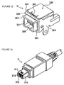
- FIGS. 15 and 16 of this application show such a conventional shielded connector.
- FIG. 15 illustrates a receptacle style connector R
- FIG. 16 illustrates a plug style connector P .
- the receptacle connector R is typically smaller in size than the plug connector P , so it should be understood that the drawings are not to scale and that the representative size of the receptacle connector R has been enlarged for clarity.
- the shield of the connector is composed of a metal shell 320 that is disposed on the outer surface of the connector housing. It is shaped in a substantially U-shape as viewed from the top and the connector shield also includes a metal shield plate 330 that is U-shaped in cross-section that is disposed between the metal shell 320 and the connector insulative housing.
- the metal shell 320 is formed so as to cover three surfaces, i.e., the front surface and both side surfaces of the insulative housing, while the shield metal plate 330 is disposed to cover three surfaces, i.e., the top surface and both side surfaces of the insulating housing.
- An engagement piece 303 is provided on the metal shield plate 320 that is engaged with an engagement recess portion 311 of a terminal portion 310 that serves as a metal shield for opposing the plug connector P .
- the metal shell 320 has a front surface shield portion 323 and side surface shield portions 324 on both sides of the connector.
- An engagement sleeve portion 307 has an opening 321 into which the terminal portion 310 of the plug connector P is inserted, and is provided in the front surface 323 of the shield portion. As illustrated, the engagement sleeve portion 307 is formed substantially into a rectangular sleeve shape so that it projects outwardly on the front surface of the connector.
- This metal shell 320 is typically formed by drawing that specific portion of the engagement sleeve portion 307, after the entire metal shield plate has been stamped out from a blank.
- a convex portion 308 may be formed as a polarizing portion that is engaged with a recess 312. Pin contacts 313 are arranged within the plug connector P .
- Connectors such as those shown in FIGS. 15 & 16 tend to be small in size, as well as the circuit boards upon which they are mounted. However, it is desirable to reduce the manufacturing cost of such connectors without losing the dimensional stability of the connector. Thus, it is a goal of this invention to keep the connector small in size while maintaining the dimensional stability of the shield and retaining its electrical properties.
- the conventional connector housing used with such connectors is formed substantially into a box-like shape with six surfaces. In view of the inherent function of the insulative housing, it is sufficient to have the housing to support the shield member in its extent around the housing and its internal contacts, as well as supporting the contacts. In the aforementioned conventional connectors, although the housing has structure supports the metal shield and has a desired mechanical strength, it has an unnecessarily large thickness for its structural stability. This creates a problem that inhibits the goal of attaining further miniaturization and weight reduction.
- the present invention is directed to an improved connector that overcomes the aforementioned disadvantages.
- It is therefore a general object of the present invention is to provide a shielded connector that is reduced in size and in weight, particularly on the receptacle side of the connector, and which is further durable suitable for repeated use in insertion and removal cycles, thereby giving a reliable connection to an opposing plug connector, yet being stable during engagement of the two connectors and being effective in shielding the contacts of the connector from electrical noise when connected to an opposing plug connector.
- Another object of the present invention is to provide a reduced size receptacle connector of the USB type for mounting on a circuit board, the connector having a connector body having top and bottom walls extending horizontally therefrom, but without having any sidewalls, the top and bottom walls cooperating with side pieces of a metal shell overlying the connector housing to define an internal cavity of the connector that engages with an opposing plug connector.
- Yet another object of the present invention is to provide a reduced size and weight USB style connector in which the connector includes a housing formed from electrically insulative material, the connector housing having a body portion that supports a plurality of conductive terminals thereon, the connector housing further including top and bottom walls extending forwardly from the housing body portion in a cantilevered fashion, and the connector housing not having any vertical sidewalls for joining the top and bottom walls together, the connector further including a conductive metal shell encircling most of the exterior surface of the connector body, the shell including a top plate, a front plate and two side plates that are formed around the top and bottom plates and the connector body, the metal shell side plates defining the sidewalls of the receptacle of the connector and the metal shell retaining a separate metal shield member in place upon the connector housing.
- Yet still another object of the present invention is to provide a reduced size connector for mounting to a circuit board.
- the connector having a reduced size by virtue of its structure which includes an insulative inner housing portion that includes top and bottom walls cantilevered from a body portion, the top and bottom walls defining the top and bottom extends of a plug-receiving receptacle, the connector housing includes a shield component mounted thereon that includes side pieces that extend between the top and bottom walls of the connector housing and which, with the top and bottom walls, cooperatively define a receptacle of the connector.
- a first means of the present invention is characterized by way of a shielded connector having an insulative housing at least one conductive contact, and a shield member that overlies a surface of the connector housing, the shield member having a metal shell with a frame portion for surrounding an opening of the housing, the opening holding at least one conductive terminal of the connector, a metal shield disposed between the metal shell and the connector housing, wherein the connector housing is formed without sidewalls, but retains a top wall, a bottom wall and an intermediate contact support that project longitudinally through the connector housing, the open sidewall portions of the connector housing being covered by portions of the shield member.
- the sidewalls of the connector housing may be eliminated, and thus it is possible to attain both of the goals of miniaturization of the connector and weight reduction of the connector insofar as the eliminated sidewalls are concerned. Also, because both of the opened sidewalls of the connector housing are covered by the shield member, it is possible to maintain both sufficient shield performance of the entire connector, and also maintain the desired mechanical strength of the connector.
- a second means of the present invention is characterized by the metal shield which has a top surface shield portion for covering the top surface of the connector housing, two side surface shield portions for covering both open sides of the connector housing, and spring portions for holding the receptacle connector together in engagement with a plug connector, the spring portions having left and right side surfaces facing inwardly of the connector and in opposition to sides of the opposing plug connector.
- the spring portions are provided on the side surface shield portions and because the connector housing has no sidewalls, the spring portions may be brought into contact with the opposing side surfaces of the plug connector to thereby will hold the plug connector effectively in a stable condition without any rattling or displacement.
- the electrical connection effected by the connector is stable in a manner in which any transmitted electrical noise is passed directly to the ground located on the circuit board to which the receptacle connector is mounted.
- the spring portions are brought into contact with the side surfaces of the opposing plug connector, so that resistance due to friction between the spring portions and the side surfaces of the plug connector is sufficient to maintain the two connectors engaged together. The stability that occurs during insertion and removal of the two connectors is enhanced due to this frictional resistance caused by the spring pieces.
- a third means of the present invention is characterized in that an engagement piece is provided on the top of the receptacle connector that engages with a recessed portion of the surface of the plug connector. This engagement piece is guided into the insulating housing of the connector through an opening that is formed in the top plate portion of the connector housing. According to this means, the engagement piece is provided on the top surface shield portion of the metal shield so that it will engage the recessed portion of the surface of the opposing plug connector to hold the plug connector in place within the receptacle connector.
- this engagement piece similarly exerts a position along the top face of the plug connector, thereby holding the plug connector in place within the receptacle connector by exerting a force on the plug connector in three distinct directions. It is possible therefore to further enhance the stability of the connector during repeated insertion and removal, as well as the electrical connection between the plug and receptacle connectors.
- the top plate portion of the connector housing is formed with an opening for receiving the engagement piece within the confines of the connector housing, so that this opening also contributes to the weight reduction obtained with the present invention.
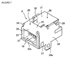
- FIGS 1-14 An improved shielded connector R constructed in accordance with the principles of the present invention is illustrated in FIGS 1-14 and in the embodiment shown, a "DIP" type electrical connector of USB style is illustrated as an example of a connector to which the principles of the present invention may be applied.
- the connector shown is one that is intended to be mounted on a substrate, such as a circuit board (not shown).
- the shielded connector R is provided with an inner insulative housing for supporting one or more conductive terminals or contacts 1, and a metal shell 20 for overlying the outer surface of the connector housing to thereby shield the terminal 1.
- the metal shell 20 includes a front frame portion or panel 22 that defines an opening 21 in the shell 20 and the connector R . This opening 21 receives a portion of an opposing plug connector P , such as the one shown in FIG. 16.
- the frame portion 22 can be seen to entirely surround the opening 21.
- the front frame portion 22 is seamless and it surrounds the entire extent, or circumference, of the opening 21.
- the front frame portion 22 may include, if desired, a convex portion 22a that has a profile greater than that of the frame, i.e., is larger than it, so as to form a polarizing feature at the opening 21 that mates with a corresponding recessed portion of the opposing plug connector P .
- the opposing plug connector P will be substantially the same in size and detail as that shown in FIG. 16, so that it is not necessary to reproduce it here.
- the insulative housing 10 of the connector has a box-like shape with a plurality of openings.
- the housing 10 is preferably formed by molding from a resin or plastic that possesses a high mechanical strength.
- the connector housing 10 has a top plate, or wall portion, 10a that forms a part of its top surface, a bottom plate, or wall portion, 10b that forms a part of the bottom surface of the connector housing, a front surface, or wall portion, 10c with an insertion opening 21 formed therein for receiving a leading portion of the opposing plug connector P , and a rear body portion 10d having an extended opening 11a through which the conductive terminals 1 extend for connection to a circuit board (not shown).
- the top and bottom wall portions 10a, 10b are cantilevered out from the rear body portion 10d.
- These terminals 1 may include solder tails that may be surface mounted to the circuit board, or as illustrated, they may include the through hole tails illustrated.
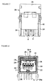
- the housing 10 is formed with out any sidewalls, or side plate portions. Rather, it has a general U-shape in cross-section, as shown in FIG. 4 with a terminal support wall portion 11 disposed between the top and bottom wall portions 10a, 10b.
- the terminal support wall portion 11 is also cantilevered from housing rear body portion 10d.
- the housing 10 includes an opening 10e in its top surface that receives the engagement portion 32 of a metal shield 30 that is applied to the top plate portion 10a of the housing 10.
- This top plate portion 10a includes a front portion 10c (FIG. 3) that has a thin recessed portion 10f formed therein which approximately matches the thickness of the metal shell 20. This is because the metal shell 20 extends partially over the metal shield 30 and accordingly, the thickness of the top plate portion 10a is reduced so that the exterior surface of the metal shell 20 will be flush with the surface of the metal shield 30.
- the housing rear body portion 10d preferably has a large thickness as compared to the plate portions for the purpose of enhancing the mechanical strength of the connector housing 10.
- the connector housing 10 has a substantial box-like shape and is provided in its interior portion with an inner or central terminal support portion 11 that supports one or more conductive terminals 1 in the connector housing 10.
- the terminals are shown best in FIG. 3 and each includes an extended contact portion 3 formed along the body thereof and a tail portion 4 that extends out of the connector housing 10.
- the housing terminal support portion 11 has an opening that receives the terminal and includes a ledge or end portion 13 against which a tip end 2 of the terminal 1 bears.
- the contact portion 3 of the terminal protrudes through the bottom of the terminal support portion 11 and extends into part 12 of the connector insertion opening.
- the contact portion 3 is formed near the free tip end 2 of the terminal 1, so that the spring effect that ensures good contact between the terminal 1 and a facing terminal of an opposing connector P is enhanced.
- the tail portions 4 of the terminals 1 exit the housing 10 by way of a rear passage or port 11a, and may be bent downwardly to extend straight and project through the lower part of the connector housing 10.
- the tails 4 may extend straight as illustrated for insertion into a through hole formed in the circuit board to which the connector is mounted or they may be bent into a horizontal plane for soldering to contact pads on the circuit board.
- the receptacle connector R illustrated is shown as a four-pin connector having four terminals 1 arranged within the connector housing 10. In order to avoid bunching of the terminal tails 4, the tails are staggered as shown in FIG. 3. Other terminal arrangements and total are contemplated.
- the metal shell 20 is formed after it is stamped out of a suitable metal blank by bending it.
- the metal blank 20A is illustrated in plan view in FIG. 10. It can be seen to include a front surface shield portion 23 indicated at 1 ⁇ , two side surface shield portions 24 on both sides of the front surface but spaced apart therefrom as indicated at 2 ⁇ , a top surface shield portion 25 as indicated by 3 ⁇ , a bottom surface shield portion 26 as indicated at 4 ⁇ , two engagement pieces 27 as indicated by 5 ⁇ and fixing pieces 28 as indicated by 6 ⁇ . All these portions form the part of the metal shell that overlies the outer surfaces of the connector housing 10.
- the overlying portions indicated by 1 ⁇ to 6 ⁇ are formed by bending them along the broken lines in FIG. 10.
- the metal shell 20 has what may be considered as an overlapped structure where at least one portion overlies each of five of the six surfaces of the connector housing 10. Therefore the metal shell 20 has at least one portion that overlies five of the six surfaces of the connector housing that are all formed by way of bending or forming so that the metal shell 20 may be fixed readily and firmly to the connector housing 10.
- Joint portions (FIG. 1) of the shell 20 are formed during the bending of the metal shell 20 along the broken lines of FIG. 10. These joint portions include the engagement pieces 27 that are located on both sides of the connector housing 10 and which are received within corresponding complementary shaped cutaway openings 29 so that both the engagement pieces 27 and the sidewalls 24 of the metal shell 20 are flush with each other. As a result, these joints do not project outwardly on the exterior surface of the connector.
- the cutaway openings 29 of the shell sidewalls 29 are preferably sized so as to accommodate the engagement pieces 27 as members of the same thickness.
- the metal shell 20 may also include tabs 24a that project from the metal shell 20 and which are received within slots formed on the circuit board, which will typically have contacts that lead directly to an earth or ground of the device in which the connector R is used.
- FIG. 1 illustrates the metal shell applied to the connector R after bending with the metal shell 20 applied to the connector housing 10.
- the metal shield 30, that is also stamped from a metal blank and which is bent into its desired shape is also provided in place on this connector R .
- the metal shield 30 is disposed between the insulative housing 10 and the metal shell 20 and is restricted in its place upon the housing 10 by the metal shell 20.
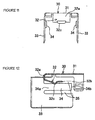
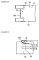
- FIG. 11 is a frontal elevational view of the metal shield, with a cross-sectional view of the shield being illustrated in FIG. 13 and a right side elevational view is shown in FIG. 14.
- the metal shield 30 is formed into a U-shape as viewed from the front end thereof and it includes a top surface shield portion 31 that covers a part of the top surface of the connector housing 10. It also includes two side surface shield portions 33 that cover both of the open sides of the connector housing 10, and each of the side shield portions 33 include spring pieces 34 formed therewith.
- the metal shield further includes an engagement piece 32 that, as best illustrated in FIG. 3, projects to the interior of the metal shield 30 and the connector housing 10. This engagement piece is designed to interferingly contact an opposing recess 311 of a plug connector P as shown in FIG. 16.
- Each of the spring pieces 34 functions to hold the opposing plug connector P in place with the receptacle connector opening 21, when the plug connector P is inserted into the receptacle connector R .
- These spring pieces 34 lie in opposition to the sides of the plug connector side walls 310.
- Each spring piece 34 takes the form of a plate with body portions 34a (FIG. 12) that are formed as part of the side surface shield portions 33 and with free end portions 34b that extend from the body portions 34a.
- the free end portions 345 extend on the sides of the rear surface of the connector housing along the side surface shield portions.
- Slots 35 are preferably formed in both the side surface shield portions 33 so that the spring pieces 34 may move freely from the side surface shield portions 33 and act as a pair of spring arms.
- each of the spring pieces 34 projects slightly inwardly along the order of a thickness of the plate from which the shield 30 is stamped. This inward projection is illustrated in FIG. 11. This projection is attained by bending the spring pieces 34 in the area of their body portions 34a. Each of the spring pieces 34 will lie along the inner wall of the metal shield and in the connector receptacle opening 21, into which the plug connector P is inserted. These two spring pieces 34 exert a retaining pressure on the opposing plug connector P in the horizontal direction from the left and right sides of the connector spring 21.
- the metal shield 30 also has an engagement piece 32 that is formed therewith and which is bent inwardly at a front end 32a thereof so that a free end portion 32b of the engagement piece 32 extends and is received in a portion of the connector housing 10.
- the engagement piece 32 extends into the interior receptacle of the connector R through an opening, or window formed in the connector housing top wall member 10.
- the free end 32a has a bent, preferably convex portion 32c formed thereon that will engage with recessed, or open portions, 311 that is provided on the outer shell 310 of the plug connector P . See FIG. 16. This engagement piece 32 exerts a retaining force on the plug connector P in the vertical direction and along the top surface of the plug connector.
- the sidewalls of the connector housing 10 are omitted (i.e., open) so that the connector housing 10 itself may be reduced both in size and in weight.
- the window in the top wall member also assists in reducing weight. This permits the connector to achieve the goal of significant reduction size and in weight to the point where connectors of the present invention may be made at one-third the size of comparable conventional connectors shown in FIG. 15.
- the overall mechanical strength of the connectors of the invention is not affected because the open sides of the connector housing 10 are covered by the side surface shield portions 24, 33 of the metal shell 20 as well as the side surfaces of the metal shield 30, so that the electrical and mechanical performance of the connector is maintained.
- the side surface portions 33 of the metal shield 30 have their spring pieces 34.
- the sidewalls of the connector housing 10 are open so that these two spring pieces 34 are capable of contacting the side surfaces of the plug connector shell 310. Consequently, the shell 310 and the plug connector P are held in place within the receptacle connector R in a stable manner without any displacement. Therefore, the electrical connection between the plug connector P and the receptacle connector R is maintained in a stable condition which makes it possible to effectively convey any transmitted electrical noise to the ground located in the circuit board by way of the receptacle shield 30 that is in contact with the metal shell 20 and its attachment legs 24.
- the spring pieces 34 themselves contact the outer surface of the plug connector shell 310 and serve to stabilize the frictional resistance that occurs during insertion and removal of the plug connector P .
- These spring pieces 34 are disposed on the right and left sides of the connector housing 10 and clamp and hold the plug shell 310 on both right and left sides thereof. These two spring pieces enhance both the grounding aspect of the two connectors and the stability of the connector R during insertion and removal of the plug connector P therefrom.
- Each spring piece 34 may take the form of a plate having a free end portion 34a extending along the rear surface side of the connector housing 10 and along the side surface shield portion 33. This both simplifies the manufacturing of the connector R but also reduces its manufacturing cost in that only simple machine work, such as bending, need be performed on the spring pieces 34 in a direction close to each other (i.e., inwardly, with respect to the connector receptacle 21) and thus it is possible to bring the pieces 34 into reliable contact with the outer surfaces of the plug connector shell 310. Because the spring pieces 34 are in the form of plates, it is possible to bring it into uniform contact with the outer surface of the plug connector outer shell 310.
- each spring piece 34 extends rearwardly along the connector housing 10 in the insertion direction of the plug connector P , but do not interfere with the insertion of the plug connector P . Additionally, the spring pieces 34 and the engagement piece 32 exert a retention force on the insertion plug of the plug connector P , on three of the low sides of the insertion plug, which increases the mechanical and retention stability of the connector.
- the forming of the metal shell 20 by stamping does not weaken the exterior frame 22 or the receptacle opening 21 that receives the plug end of the plug connector P , so that the stability of the opening 21 is enhanced. Also, because the metal shell is stamped and formed rather than drawn and formed, the manufacturing cost is reduced. Furthermore, the elimination of the connector housing sidewalls and the use of the opening for the engagement piece cooperate to reduce the overall size of the connector.
- the frame portion 22 is stamped as a continuous extent of metal that surrounds the opening 21 and is formed without drawn or joint portions, so it will exhibit superior mechanical strength.
Landscapes
- Details Of Connecting Devices For Male And Female Coupling (AREA)
- Coupling Device And Connection With Printed Circuit (AREA)
Abstract
Description
Claims (18)
- A reduced size receptacle connector for effecting a connection between a plug connector and a circuit board, comprising:a connector housing formed of electrically insulative material, the connector housing having a body portion, a top wall member and a bottom wall member extending from the housing body portion in a cantilevered fashion, the top and bottom wall members being spread apart to define a space for receiving an insertion end of the plug connector, the connector housing not having any sidewall members that interconnect said top and bottom wall members together;at least one conductive terminal supported by said connector housing in said space between said top and bottom wall members, the terminal having a tail portion for attachment to a circuit board extending out of said connector housing;a metal shell member overlying part of said connector housing and having at least two sidewall portions that extend vertically between said top and bottom wall members, said connector housing top and bottom wall members and said shell sidewall portions cooperatively defining a receptacle of said connector for receiving said plug connector insertion end.
- The connector of claim 1, wherein said connector housing includes a support member extending from said body portion in a cantilevered fashion, between said top and bottom wall members, said support member supporting said one terminal.
- The connector of claim 2, further including a plurality of conductive terminals supported on said support member, said terminals having contact portions that are supported on said support member and tail portions that extend out of said connector housing for attachment to a circuit board.
- The connector of claim 3, where said connector housing body portion has a passage that extends from said receptacle to exterior of said connector housing, said terminals extending through said passage so that said tail portions thereof are disposed exterior of said connector housing.
- The connector of claim 1, wherein said shell includes a front face, the front face having an opening that communicates with said receptacle.
- The connector of claim 5, where said front face includes a continuous edge portion that encompasses said opening.
- The connector of claim 1, wherein said shell includes a metal blank having a front face portion, a top wall portion integrally attached to said front face portion, a bottom wall portion integrally attached to said front face portion and two sidewall portions integrally attached to said top wall portion, said two sidewall portions flanking said top wall portions.
- The connector of claim 7, wherein said shell top wall portion overlies said connector housing top wall member, said shell bottom wall portion overlies said connector housing bottom wall portion and said shell two side wall portions extend vertically between said connector housing top and bottom wall members.
- The connector of claim 1, further including means for polarizing said connector receptacle, the polarizing means including a rib extending lengthwise from said connector housing body portions in said connector receptacle, the rib presenting a convex profile within said receptacle for engaging with a corresponding recess formed in said plug connector insertion end.
- The connector of claim 9, wherein said rib is formed as part of said connector housing bottom wall member.
- A receptacle connector, comprising:a connector housing, the housing having a body portion, a top wall portion, a bottom wall portion and a terminal support portion, the top and bottom wall portions and terminal support portions being spaced apart from each other and extending outwardly in different, generally horizontal planes from said housing body portions;a plurality of conductive terminals supported by said terminal support portion, said top and bottom wall portions defining interior surfaces of a receptacle of said connector, the terminals having contact portions disposed in said receptacle and tail portions that extend away from said connector housing bottom portion; anda metal shell overlying portions of said connector housing, said metal shell having at least two side walls that extend vertically between said connector housing top and bottom wall portions, such that said metal shell sidewalls and said connector housing top and bottom wall portions cooperatively defining a receptacle of said connector for receiving the insertion end of an opposing plug connector.
- The receptacle connector of claim 11, wherein said metal shell has a face portion that extends between said connector housing top and bottom wall portions and which defines a front end of said receptacle connector, said shell face having an opening formed therein that provides a passage to said receptacle from said exterior of said connector.
- The receptacle connector of claim 11, wherein said top and bottom wall portions and said terminal support portions are cantilevered members that extend lengthwise out from said connector housing body portion.
- The receptacle connector of claim 11, where said connector having bottom wall member includes a polarizing key extending for the length of said bottom wall member, the polarizing by extending into said receptacle for engagement by a corresponding recess formed in an opposing connector insertion portion.
- The receptacle connector of claim 11, wherein said metal shell overlies part of said top and bottom wall portions and said metal shell includes a front face portion that defines an opening to said receptacle, the front face extending between front edges of said connector housing top and bottom wall portions.
- The receptacle connector of claim 11, wherein said top and bottom wall portions extend in first and second different, generally horizontal planes and said connector housing metal shell sidewalls extends in third and fourth different planes that are generally perpendicular to said connector housing top and bottom wall portion horizontal planes.
- The receptacle connector of claim 15, wherein said metal shell sidewalls are attached to said front face and are bent along foldlines to form said sidewall of said connector receptacle.
- A reduced size and weight connector for providing a connection between a plug connector and circuits on a circuit board, comprising:a connector housing for supporting a plurality of conductive terminals thereon, the housing having a rear body portion and top and bottom wall portions extending therefrom in a cantilevered fashion, said top and bottom wall portions forming top and bottom walls of an interior receptacle of said connector for receiving an insertion part of an opposing plug connector, said terminals being disposed between said connector housing, top and bottom wall portions;a metal shell covering part of said connector housing and extending over parts of said connector housing top and bottom wall members, said shell including a front face portion that extends between front edges of said top and bottom wall members, a top portion that overlies a portion of said top wall member, a bottom portion that extends around a portion of said bottom wall member and two sidewalls that extend vertically between said connector housing top and bottom wall members said metal shell two sidewalls forming left and right sidewalls of said connector interior receptacle, said metal shell sidewalls and top and bottom wall members defining said receptacle, said connector housing not having any sidewalls interconnecting said top and bottom wall members.
Applications Claiming Priority (2)
| Application Number | Priority Date | Filing Date | Title |
|---|---|---|---|
| JP27636399 | 1999-09-29 | ||
| JP27636399A JP4417491B2 (en) | 1999-09-29 | 1999-09-29 | Shield type connector |
Publications (2)
| Publication Number | Publication Date |
|---|---|
| EP1089396A2 true EP1089396A2 (en) | 2001-04-04 |
| EP1089396A3 EP1089396A3 (en) | 2001-11-28 |
Family
ID=17568395
Family Applications (1)
| Application Number | Title | Priority Date | Filing Date |
|---|---|---|---|
| EP00120811A Withdrawn EP1089396A3 (en) | 1999-09-29 | 2000-09-23 | Reduced-size connector |
Country Status (5)
| Country | Link |
|---|---|
| EP (1) | EP1089396A3 (en) |
| JP (1) | JP4417491B2 (en) |
| KR (1) | KR100407443B1 (en) |
| CN (1) | CN1214496C (en) |
| TW (1) | TW481384U (en) |
Cited By (2)
| Publication number | Priority date | Publication date | Assignee | Title |
|---|---|---|---|---|
| CN102544925A (en) * | 2012-01-17 | 2012-07-04 | 东莞市扬明精密塑胶五金电子有限公司 | Crosstalk-proof electrical connector for single-row welding wires |
| US9728917B2 (en) | 2013-05-07 | 2017-08-08 | Alan L. Pocrass | High profile USB connector |
Families Citing this family (9)
| Publication number | Priority date | Publication date | Assignee | Title |
|---|---|---|---|---|
| CN1437089B (en) * | 2002-02-05 | 2012-01-25 | 劲永科技(苏州)有限公司 | Connection device for USB interface and memory storage device thereof |
| CN101051719A (en) * | 2002-05-24 | 2007-10-10 | Fci公司 | Improved plug |
| JP4321710B2 (en) | 2004-04-07 | 2009-08-26 | タイコエレクトロニクスアンプ株式会社 | Shield type connector |
| JP4605591B2 (en) * | 2004-12-14 | 2011-01-05 | 株式会社アイペックス | Electrical connector |
| KR100826200B1 (en) * | 2006-09-15 | 2008-04-30 | 엘지전자 주식회사 | Motor with moisture penetration prevention structure |
| JP4851355B2 (en) * | 2007-02-06 | 2012-01-11 | 株式会社オートネットワーク技術研究所 | Outer conductor terminal and shield connector |
| JP6422815B2 (en) * | 2015-04-21 | 2018-11-14 | 日本航空電子工業株式会社 | connector |
| CN108736213B (en) * | 2017-04-19 | 2021-04-20 | 富士康(昆山)电脑接插件有限公司 | Electrical connector |
| FR3091138B1 (en) * | 2018-12-21 | 2022-07-22 | Valeo Siemens Eautomotive France Sas | Electrical assembly comprising integrated electromagnetic shielding means |
Family Cites Families (8)
| Publication number | Priority date | Publication date | Assignee | Title |
|---|---|---|---|---|
| US4842554A (en) * | 1988-06-03 | 1989-06-27 | Amp Incorporated | One-piece shield for a circular din |
| US5207597A (en) * | 1991-06-21 | 1993-05-04 | Amp Incorporated | Shielded connector with dual cantilever panel grounding beam |
| US5192228A (en) * | 1991-09-16 | 1993-03-09 | Amp Inc. | Shielded surface mount electrical connector with integral barbed board lock |
| US5564949A (en) * | 1995-01-05 | 1996-10-15 | Thomas & Betts Corporation | Shielded compact data connector |
| JP3070003B2 (en) * | 1996-09-06 | 2000-07-24 | タイコエレクトロニクスアンプ株式会社 | Shield type connector and manufacturing method thereof |
| US5865646A (en) * | 1997-03-07 | 1999-02-02 | Berg Technology, Inc. | Connector shield with integral latching and ground structure |
| US6162089A (en) * | 1997-12-30 | 2000-12-19 | The Whitaker Corporation | Stacked LAN connector |
| JP2001085113A (en) * | 1999-09-16 | 2001-03-30 | Molex Inc | Shielded connector |
-
1999
- 1999-09-29 JP JP27636399A patent/JP4417491B2/en not_active Expired - Fee Related
-
2000
- 2000-09-23 EP EP00120811A patent/EP1089396A3/en not_active Withdrawn
- 2000-09-28 KR KR10-2000-0056920A patent/KR100407443B1/en not_active Expired - Fee Related
- 2000-09-29 CN CNB001290576A patent/CN1214496C/en not_active Expired - Fee Related
-
2001
- 2001-01-30 TW TW089216827U patent/TW481384U/en not_active IP Right Cessation
Cited By (2)
| Publication number | Priority date | Publication date | Assignee | Title |
|---|---|---|---|---|
| CN102544925A (en) * | 2012-01-17 | 2012-07-04 | 东莞市扬明精密塑胶五金电子有限公司 | Crosstalk-proof electrical connector for single-row welding wires |
| US9728917B2 (en) | 2013-05-07 | 2017-08-08 | Alan L. Pocrass | High profile USB connector |
Also Published As
| Publication number | Publication date |
|---|---|
| CN1290054A (en) | 2001-04-04 |
| EP1089396A3 (en) | 2001-11-28 |
| CN1214496C (en) | 2005-08-10 |
| KR20010030518A (en) | 2001-04-16 |
| JP4417491B2 (en) | 2010-02-17 |
| JP2001110527A (en) | 2001-04-20 |
| KR100407443B1 (en) | 2003-11-28 |
| TW481384U (en) | 2002-03-21 |
Similar Documents
| Publication | Publication Date | Title |
|---|---|---|
| US6926557B1 (en) | Shielded connector of reduced-size with improved retention characteristics | |
| US5915976A (en) | High speed connector | |
| US6109967A (en) | Electrical connector with shield | |
| US4571012A (en) | Shielded electrical connector assembly | |
| US9106024B2 (en) | Electrical connector with a metal plate for preventing electromagnetic interference | |
| US5308251A (en) | Mounting bracket with ESD protection for an electrical connector | |
| US6190205B1 (en) | Electrical jack | |
| US6093058A (en) | Electrical jack | |
| US20040157491A1 (en) | Electrical connector | |
| US5611711A (en) | Electrical connector assembly | |
| US5775932A (en) | Electrical connector | |
| US5967846A (en) | Shields for electrical connector mated pair | |
| US7008762B2 (en) | Electrical connector assembly having grounding function | |
| US6155878A (en) | Electrical connector with separate shield and grounding member | |
| US6168467B1 (en) | Receptacle connector | |
| US20060030220A1 (en) | Electrical connector with an internal modem | |
| EP1089396A2 (en) | Reduced-size connector | |
| US7410390B2 (en) | Electrical receptacle connector with shell | |
| US6343941B1 (en) | Grounding mechanism used in terminal connector structures | |
| US6293825B1 (en) | Electrical connector | |
| US6080016A (en) | Electrical connector assembly | |
| JPH0680283U (en) | Electrical connector | |
| JP4074022B2 (en) | Shield connector | |
| US6793538B2 (en) | Slim modular jack | |
| GB2329529A (en) | Shielded connector |
Legal Events
| Date | Code | Title | Description |
|---|---|---|---|
| PUAI | Public reference made under article 153(3) epc to a published international application that has entered the european phase |
Free format text: ORIGINAL CODE: 0009012 |
|
| AK | Designated contracting states |
Kind code of ref document: A2 Designated state(s): DE FR GB IT Kind code of ref document: A2 Designated state(s): AT BE CH CY DE DK ES FI FR GB GR IE IT LI LU MC NL PT SE |
|
| AX | Request for extension of the european patent |
Free format text: AL;LT;LV;MK;RO;SI |
|
| PUAL | Search report despatched |
Free format text: ORIGINAL CODE: 0009013 |
|
| AK | Designated contracting states |
Kind code of ref document: A3 Designated state(s): AT BE CH CY DE DK ES FI FR GB GR IE IT LI LU MC NL PT SE |
|
| AX | Request for extension of the european patent |
Free format text: AL;LT;LV;MK;RO;SI |
|
| AKX | Designation fees paid |
Free format text: DE FR GB IT |
|
| STAA | Information on the status of an ep patent application or granted ep patent |
Free format text: STATUS: THE APPLICATION IS DEEMED TO BE WITHDRAWN |
|
| 18D | Application deemed to be withdrawn |
Effective date: 20020529 |