BACKGROUND OF THE INVENTION
1. Field of the Invention
-
The present invention relates to an explosion-proof tape
of a cathode-ray tube and an explosion-proof structure of the
cathode-ray tube, in which a metal band shrink-fitted to the
outer circumference of the cathode-ray tube through the tape
can be removed easily so that the cathode-ray tube can be recycled
efficiently. The present application is based on Japanese
Patent Application No. Hei. 11-275687, which is
incorporated herein by reference.
2. Description of the Related Art
-
A cathode-ray tube often used as a television picture
tube, a monitor for a personal computer, a word processor, etc.,
or the like, is subjected to explosion-proof treatment so as
to be prevented from implosion because the cathode-ray tube
is formed as a glass tube the inside of which is at a vacuum.
A structure where an explosion-proof tape is wound on the outer
circumference of a panel portion of the cathode-ray tube and
a metal band is shrink-fitted on the tape is a typical one of
the explosion treatment. According to such an explosion-proof
structure, a bending moment generated by the atmosphere against
the front surface of the cathode-ray tube due to the vacuum
inside the cathode-ray tube is relieved and reduced by an opposite
bending moment acting on the basis of the clamping pressure
of the metal band so that the implosion is prevented.
-
In the background art, as such an explosion-proof tape,
there has been known a tape in which a rubber or acrylic adhesive
layer or the like to adhere to a cathode-ray tube in high strength
is provided on a support formed by laminating a polyester or
polyethylene layer on a glass or cotton cloth. According to
this explosion-proof tape, when the explosion-proof tape is
bonded with a cathode-ray tube through the adhesive layer and
a metal band is shrink-fitted thereon, the support of the
explosion-proof tape is fused to adhere to the metal band firmly.
-
However, when it is attempted to salvage an abandoned
cathode-ray tube and reclaim glass material therefrom in view
of the preservation of global environment, the effective use
of resources, and so on, it is difficult to break up the
cathode-ray tube because the metal band firmly adheres to the
cathode-ray tube through the fused solid layer of the
explosion-proof tape. In addition, there is a problem that the
fused solid support of the explosion-proof tape projecting from
the metal band adhere to the cathode-ray tube firmly so that
it takes much time and much labor for the work of erasing the
fused solid substances, the processing of grinding them, or
the like. Thus, such problems have been obstacles to recycling
cathode-ray tubes.
-
In the above-mentioned case, if it is insufficient to
erase the fused solid layer of the explosion-proof tape from
the cathode-ray tube, the components of the explosion-proof
tape are carbonized to lower the quality of glass material
obtained by the operation of reduction thereof when the
cathode-ray tube is broken up into a panel portion and a funnel
portion in the form of cullet and the cullet is fused to obtain
reclaimed glass. Particularly high-purity is required of lead
glass which forms the panel portion of the cathode-ray tube.
Therefore, such inclusion of impurities makes it difficult to
reclaim lead glass for forming the panel portion.
-
In addition, in the background-art explosion-proof
structure, in the case where there arises an error in bonding
such as a displacement of the metal band, the fused solid
substances of the explosion-proof tape remain on the cathode-ray
tube even if the metal band is cut and removed. As a result,
not only is it difficult to remove the fused solid substances,
but also it is apt to damage the cathode-ray tube. If the
cathode-ray tube is damaged when the remainders of the
explosion-proof tape are removed, there arises a fear that the
cathode-ray tube implodes due to stress concentration. Thus,
the cathode-ray tube should not be put into practical use.
SUMMARY OF THE INVENTION
-
It is an object of the present invention to develop an
explosion-proof tape and an explosion-proof structure for a
cathode-ray tube, in which the explosion-proof tape applied
onto the outer circumference of a panel portion of the cathode-ray
tube as explosion-proof treatment, and a metal band
shrink-fitted on the explosion-proof tape can be removed easily
and safely so that the breaking-up and recycling of the
cathode-ray tube or the reclamation of the cathode-ray tube
unsuccessful in the explosion-proof treatment can be performed
efficiently.
-
According to the present invention, there is provided
an explosion-proof tape wound on an outer circumference of a
panel portion of a cathode-ray tube so that a metal band is
shrink-fitted on the tape, the tape comprising: a support having
at least a layer composed of propylene polymer with a propylene
content of not less than 40 weight % or styrene polymer with
a styrene content of not less than 50 weight %; and an adhesive
layer formed on one surface of the support in a manner so that
a plurality of fibers with a softening point of not lower than
200°C are buried in the adhesive layer in a lengthwise direction
of the tape. There is further provided an explosion-proof
structure of a cathode-ray tube, wherein a metal band is
shrink-fitted on an outer circumference of a panel portion of
a cathode-ray tube, through a layer which is formed by winding
such an explosion-proof tape as mentioned above, through its
adhesive layer.
-
According to the present invention, the shrink-fitted
metal band is heated and expanded in the same manner as when
the metal band was shrink-fitted, so that the metal band can
be removed easily and efficiently even by hand, and the
explosion-proof tape remaining on the cathode-ray tube can be
also peeled off and removed together with the adhesive layer
through the support thereof easily and efficiently even by hand.
As a result, the metal band and the explosion-proof tape applied
onto the cathode-ray tube as explosion-proof treatment are
removed easily by hand or the like so that the cathode-ray tube
can be broken up into a panel portion and a funnel portion.
The broken-up portions are subjected to fusing treatment so
that glass material kept as high in purity as that before the
treatment can be reclaimed. The reclaimed glass material can
be served for recycling efficiently as glass material with
quality equal to that before the reclamation.
-
In addition, even if there arises an error in manufacture
such as an error in bonding, for example, a divergence of the
metal band at the time of the explosion-proof treatment, the
metal band and the explosion-proof tape can be removed from
the cathode-ray tube more easily and without damaging the
cathode-ray tube. Thus, the cathode-ray tube can be salvaged
and reused efficiently without being broken up.
-
Features and advantages of the invention will be
evident from the following detailed description of the
preferred embodiments described in conjunction with the
attached drawings.
BRIEF DESCRIPTION OF THE DRAWING
-
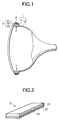
- Fig. 1 shows a sectional view of an embodiment of an
explosion-proof structure;
- Fig. 2 shows a partially sectional perspective view of
an embodiment of an explosion-proof tape; and
- Fig. 3 shows an explanatory view of an embodiment of a
process for burying fibers.
-
DETAILED DESCRIPTION OF THE PREFERRED EMBODIMENTS
-
An explosion-proof tape according to the present invention
has a support having at least a layer composed of propylene
polymer with a propylene content of not less than 40 weight %
or styrene polymer with a styrene content of not less than 50
weight % and an adhesive layer formed on one surface of the
support in a manner so that a plurality of fibers with a softening
point of not lower than 200°C are buried in the adhesive layer
in a lengthwise direction of the tape. The explosion-proof tape
is wound on the outer circumference of a panel portion of a
cathode-ray tube through the adhesive layer, and a metal band
is shrink-fitted thereon. Thus, an explosion-proof structure
is formed.
-
Fig. 1 shows an embodiment of the foregoing
explosion-proof structure, and Fig. 2 shows an embodiment of
the foregoing explosion-proof tape. The reference numeral 1
represents a cathode-ray tube constituted by a panel portion
11 and a funnel portion 12; 2, an explosion-proof tape constituted
by a support 21 and an adhesive layer 22; and 3, a metal band.
The reference numeral 23 represents fibers buried in the adhesive
layer 22.
-
According to the present invention, there is used an
explosion-proof tape in which the adhesive layer 22 is provided
on one surface of the support 21 which has at least a layer
composed of propylene polymer with a propylene content of not
less than 40 weight % or styrene polymer with a styrene content
of not less than 50 weight %, as shown in Fig. 2.
-
Examples of such propylene polymers for forming the
support include propylene homopolymer; random or block copolymer
of propylene and ethylene, ethylene-propylene rubber, or a
mixture of polypropylene and polyethylene, which are prepared
so that the propylene content is not less than 40 weight %;
a mixture using two or more kinds of such polymers; and so on.
-
Examples of such styrene polymers include styrene
homopolymer; styrene-isoprene copolymer, styrene-butadiene
copolymer, styrene-isoprene-styrene copolymer,
styrene-butadiene-styrene copolymer, or a mixture of one or
more kinds of such copolymers and styrene homopolymer, which
are prepared so that the styrene content is not less than 50
weight %; and so on.
-
From the point of the easiness in release from a
shrink-fitted metal band, it is preferable that the support
has a layer composed of propylene or styrene homopolymer at
least on the surface. On the other hand, the position where
the metal band is shrink-fitted in the cathode-ray tube is tapered
so that the band is apt to slip to produce a displacement. In
the case where measures to fix the position of the band, or
measures to prevent the displacement is desired, it is possible
to use a support which is made to contain the above-mentioned
components such as ethylene, isoprene, butadiene, etc., so that
slight adhesive force is generated between the support and the
metal band when the metal band is shrink-fitted.
-
From the point of the compatibility between the easiness
in release and the anti-slip adhesive force in the metal band,
in the case of propylene polymer, it is preferable that the
propylene content is in a range of not less than 50 weight %,
especially in a range of from 55 weight % to 95 weight %, more
especially in a range of from 65 weight % to 85 weight %. On
the other hand, in the case of styrene polymer, it is preferable
that the styrene content is in a range of not less than 60 weight %,
especially in a range of from 65 weight % to 95 weight %, more
especially in a range of from 70 weight % to 85 weight %.
-
If the propylene polymer contains the propylene content
of less than 40 weight % or the styrene polymer contains the
styrene content of less than 50 weight % in the above-mentioned
support, the adhesive force between the support and the
shrink-fitted metal band becomes so excessive that it becomes
difficult to release the metal band easily by hand or the like.
-
The support can be obtained as a film or a sheet composed
of propylene or styrene polymer, or a laminated body of such
films, or a laminated body of such a film and optionally other
bases composed of glass, cotton, or the like. From the point
of workability in release, or the like, at the time of recycling,
it is preferable that a film, a sheet, or the like, composed
of propylene or styrene polymer is used as the support.
-
The thickness of the support may be decided appropriately
in accordance with the size of the cathode-ray tube or the like.
Although the thickness can be made to be above 1 mm, it is generally
set in a range of from 5 µm to 500 µm, especially in a range
of from 10 µm to 300 µm, more especially in a range of 20 µm
to 200 µm. Suitable surface treatment such as corona treatment,
primer treatment, or the like, for enhancing the close contact
force with the adhesive layer, may be applied to the surface
of the support to which the adhesive layer is applied.
-
As illustrated, the adhesive layer 22 provided on one
surface of the support 21 may be formed of a suitable rubber
or acrylic adhesive agent or the like. A preferable adhesive
layer can be peeled off integrally with the support without
any adhesive transfer onto the cathode-ray tube. Such an
adhesive layer may be formed of a suitable known adhesive agent
which is difficult to give rise to adhesive transfer, for example,
a polyisobutylene adhesive agent, an acrylic adhesive agent
containing (meth)acrylic alkyl ester-acrylic acid copolymer
as base polymer, or the like.
-
An adhesive agent in which the residue becomes not more
than 5 weight % by heat treatment at 700°C or lower and for 30
minutes or shorter can be also used preferably. Such an adhesive
agent is decomposed or gasified by low-temperature short-time
heat treatment so as to show a good vanishing property. Thus,
the adhesive agent hardly produces a residue of tar, carbon,
or the like, causing the deterioration of the quality. Even
if the scrapped panel portion or the like is subjected to fusing
treatment while an adhesive of the adhesive layer transferred
thereto is left as it is, the adhesive of the adhesive layer
vanishes at that treatment so that high-purity glass material
can be reclaimed. In addition, when there is an error in bonding
the metal band, the adhesive layer is made to vanish by heat
treatment or the like so that the cathode-ray tube can be served
for salvage.
-
An adhesive agent showing a vanishing property in which
the residue is reduced to 5 weight % or less by heat treatment
at 700°C or lower and for 30 minutes or shorter can be formed
by use of polymer having a -O-O- group in base polymer in the
molecular chain thereof, for example, polymethylene malonic
diester such as polymethylene dimethyl malonate, polymethylene
diethyl malonate, or polymethylene dipropyl malonate; butylene
polymer; nitrocellulose polymer; α-methyl-styrene polymer;
propylene carbonate polymer; (meth)acrylic alkyl ester polymer;
copolymer of hydrazide-group containing monomer and
isocyanate-group containing monomer; etc.
-
The polymer having a -O-O- group in the molecular chain
can be prepared, for example, by such a method that monomers
such as (meth)acrylic alkylester, (meth)acrylic acid derivative
having a carboxylic-acid derived group in a side chain, styrene,
or styrene derivative, are radically polymerized while oxygen
gas is supplied to a reaction system, so that one or more
-O-O-groups are introduced into the molecular chain at random.
-
On the other hand, the polymethylene malonic diester can
be prepared, for example, by such a method that ethoxymethylene
malonic diester is hydrogenated under the existence of a catalyst
such as platinum dioxide or the like in a solvent such as methanol,
the solvent is removed, ethoxy groups are eliminated under
heating, and methylene malonic diesters obtained thus are
refined and polymerized through moisture in the atmosphere or
the like.
-
On the other hand, the copolymer of hydrazide-group
containing monomer and isocyanate-group containing monomer can
be prepared, for example, by such a method that dihydrazides
such as adipic dihydrazide, isophthalic dihydrazide, sebacic
dihydrazide, dodecanedioic dihydrazide,
1,3-bis(hydrazinocarboethyl)-5-isopropyl hydantoin,
eicosanedoic dihydrazide, or
7,11-octadecadiene-1,18-dicarbohydrazide, and diisocyanates
such as hexamethylene diisocyanate, tolylene diisocyanate,
methylene-bis(4- phenyl isocyanate), xylylene diisocyanate,
or 3-isocyanatemethyl-3,5,5-trimethylcyclohexyl isocyanate,
are subjected to polyaddition-polymerization.
-
In the above-mentioned adhesive agent, from the point
of a low-temperature short-time vanishing property, it is
preferable that the heat decomposition temperature of the base
polymer is in a range of from 150°C to 600°C, especially in a
range of from 200°C to 500°C, more especially in a range of from
250°C to 400°C, and the base polymer shows a vanishing property
in which the residue is not more than 5 weight %, especially
not more than 3 weight %, more especially not more than 2 weight %,
by heat treatment at such a heating temperature for a heating
time of not longer than 30 minutes, especially in a range of
from 3 minutes to 20 minutes, more especially in a range of
from 5 minutes to 15 minutes.
-
One or more kinds of polymers may be used as the base
polymer of the adhesive layer. Examples of base polymers which
can be used preferably from the point of a heat vanishing property
or the like, include butene polymers such as polyisobutylene,
and methacrylic polymers which have for its principal ingredient,
methacrylic ester having a glass transition point at not higher
than 30°C, especially at -20°C, such as butyl methacrylate, octyl
methacrylate, lauryl methacrylate, etc. In addition, it is
preferable that the weight average molecular weight of the base
polymer is not more than 5 million, especially in a range of
from a hundred thousand to 4 million, more especially in a range
of from 2 hundred thousand to 3 million.
-
When the adhesive layer is formed, for example, a heat
decomposition accelerator suitable to the base polymer to be
used together, such as iron sulfate, sodium nitrite, heavy metal
ions, hydroquinone, linolenic acid, ascorbic acid, cysteine,
azodicarbonamide, etc. may be blended in accordance with
necessity. In addition, a plasticizer such as dibutylphthalate
or dioctyl phthalate, a softener such as xylene oil, terpene
oil, paraffin or wax, etc. may be blended in accordance with
necessity.
-
In the adhesive layer 22, as shown in Fig. 2, a plurality
of fibers 23 having a softening point at 200°C or higher are
buried in the lengthwise direction of the explosion-proof tape.
This aims at prevention of the metal band and the cathode-ray
tube from coming in contact with each other, because of
interposition of the fibers 23. This is because there is a fear
that a high-temperature area might be produced locally due to
the temperature unevenness produced in the metal band when the
metal band is heated and expanded to be shrink-fitted. Then,
the support would be melted by the high temperature so that
the metal band would come in contact with the cathode-ray tube
so as to damage the glass of the latter. As a result, the
cathode-ray tube might explode due to stress concentration
caused by the damaged glass. Such a fear of explosion due to
contact gets serious particularly in the case of a large-size
cathode-ray tube over 30 inches.
-
The above-mentioned fibers may be composed of desirable
fibers having a softening point of 200°C or higher, for example,
polyamide fibers of nylon, aromatic series, or the like;
polyester fibers of polyethylene terephthalate or the like;
polycyclohexane terephthalate fibers; polyimide fibers;
polysulfone fibers; polyether sulfone fibers; polyamide-imide
fibers; glass fibers; carbon fibers; etc. Long-size fibers are
generally used because they can be arranged in the lengthwise
direction of the tape effectively.
-
Although the diameter of the fibers can be determined
desirably in accordance with the strength, the number of arranged
fibers, the thickness of the adhesive layer, and so on, fibers
each having a diameter of not more than 100 µm, especially in
a range of from 10 µm to 80 µm, more especially in a range
of from 30 µm to 60 µm are generally used. Although the widthwise
intervals of the fibers extending in the lengthwise direction
of the tape can be also determined desirably, the intervals
are generally set to be in a range of from 0.1 mm to 4 mm, especially
in a range of from 0.2 mm to 3 mm, more especially in a range
of from 0.5 mm to 2 mm, from the points of the above-mentioned
contact prevention effect, the layer strength of the adhesive
layer, and so on. In consideration of the width of the
explosion-proof tape per se, which is usually set to be in a
range of from 10 mm to 100 mm, especially in a range of from
20 mm to 80 mm, more especially in a range of from 30 mm to
70 mm, it is preferable that not less than 5 fibers, especially
10 to 100 fibers, more especially 20 to 50 fibers are disposed
in the width of the explosion-proof tape.
-
The adhesive layer may be applied to the support in a
desirable method, for example, a method in which an adhesive
composition is developed on the support by a desirable means
such as a doctor blade or the like, and then dried; a method
in which an adhesive layer provided on a separator in the same
manner as the above-mentioned method is transferred onto the
support; or the like. Although the thickness of the adhesive
layer may be determined desirably, it is generally set to be
in a range of from 5 µm to 500 µm, especially in a range of
from 30 µm to 200 µm, more especially in a range of from 50
µm to 100 µm.
-
The above-mentioned fibers may be buried into the adhesive
layer by a desirable method, for example, a sandwich method
in which the fibers are disposed between lamination layers when
the adhesive layer is laminated by an adhesive agent recoating
method, an adhesive layer transfer method, or the like. Fig.
3 shows a specific example of the method.
-
That is, in the illustrated method, a rolled body 42 of
an adhesive sheet 4 in which a thin adhesive layer 22a, for
example, about 20 µm thick, is provided on the surface side
of a support sheet 41 subjected to back-surface treatment with
a silicon release agent or the like, is rewound, and in the
meanwhile the adhesive layer 22a is supplied between rotating
pinch rolls 51 and 52 sequentially with a predetermined number
of fibers made to train against the adhesive layer 22a. The
fibers are bonded with and held on the adhesive layer so that
a pre-sheet 43 is obtained. After that, in a not-illustrated
process, an adhesive layer which is, for example, about 30 to
100 µm thick, is laid on the adhesive layer which holds the
fibers in the pre-sheet. Thus, an explosion-proof sheet is
formed. The formed sheet is wound up and cut into a predetermined
tape width.
-
Then, in the above description, there is such a case where
the adhesive layer is split and peeled off in the fiber portion
due to the buried fibers when the explosion-proof tape is
separated, so that adhesive transfer is apt to be produced on
the cathode-ray tube. In such a case, it is preferable that
the adhesive layer at least on the side to be bonded with the
cathode-ray tube, that is, on the side where adhesive transfer
is apt to be produced, is formed of an adhesive agent having
the above-mentioned low-temperature short-time vanishing
property. Therefore, the adhesive layer may be formed as
stratified layers composed of different kinds of adhesive
-
An explosion-proof structure for a cathode-ray tube
according to the present invention can be formed in the same
manner as in the background-art except the point that the
above-mentioned explosion-proof tape is used. For example, as
shown in Fig. 1, the explosion-proof structure can be formed
by a method in which the explosion-proof tape 1 is wound on
the outer circumference of the panel portion 11 of the cathode-ray
tube 1 through the adhesive layer 22 of the explosion-proof
tape 1, and the metal band 3 composed of steel or the like is
-
Although the explosion-proof tape which can be separated
more easily than the metal band is used according to the present
invention, force required for explosion-proof treatment on the
cathode-ray tube is equal to the clamping force (f in Fig. 1)
through the metal band which can relieve and reduce the bending
moment acting on the cathode-ray tube having a vacuum in its
inside through the atmosphere as described above. Therefore,
the clamping force can be generated satisfactorily only by the
metal band. Thus, even if the adhesive force between the metal
band and the explosion-proof tape is weak, the clamping force
by the metal band can be displayed satisfactorily. As a result,
an explosion-proof effect similar to that in the background
art can be developed also according to the present invention.
Example 1
-
A 20 µm thick adhesive layer composed of polyisobutylene
with weight-average molecular weight of about 1 million was
provided on one surface of a 50 µm thick film composed of a
mixture of 100 parts (parts by weight, similarly hereinafter)
of propylene polymer and 0.5 parts of a slip agent. Then, 30
glass fibers each having a softening point at 220°C and a diameter
of 50 µm were bonded with and held on the adhesive layer at
widthwise intervals of 1 mm along the film lengthwise direction
by the method shown in Fig. 3. Next, on the adhesive layer,
there is provided another 80 µm thick adhesive layer composed
of the above-mentioned polyisobutylene so that the total
thickness of the adhesive layers reached 100 µm. Thus, an
explosion-proof tape was obtained.
-
Next, the above-mentioned explosion-proof tape 50 mm wide
was wound on and bonded with the outer circumference of a panel
portion of a cathode-ray tube through the adhesive layer of
the explosion-proof tape. A steel band 30 mm wide was
shrink-fitted thereon by induction heating to 500°C. Thus, an
explosion-proof structure (Fig. 1) was formed.
Example 2
-
A toluene solution of an acrylic adhesive agent was applied
onto one surface of a 50 µm thick film formed by extending an
extrusion-molded film composed of a mixture of 30 parts of
propylene homopolymer, 40 parts of ethylene-propylene random
copolymer with a propylene content of 70 weight %, and 30 parts
of ethylene homopolymer. The toluene-coated film was dried,
and an adhesive layer 20 µm thick was provided thereon. Then,
in the same manner as in Example 1, 30 nylon-66 fibers each
having a softening point at 255°C and a diameter of 50 µm were
bonded with and held on the adhesive layer at widthwise intervals
of 1 mm along the film lengthwise direction. Next, on the thus
prepared adhesive layer, there is provided another 80 µm thick
adhesive layer composed of the above-mentioned acrylic adhesive
agent. Thus, an explosion-proof tape was obtained. By use of
this explosion-proof tape, an explosion-proof structure was
formed. Incidentally, in the acrylic adhesive agent, 60 parts
of dibutyl phthalate and 4 parts of melamine crosslinker were
blended in 100 parts of base polymer which was formed by
polymerization of 95 parts of butyl methacrylate and 5 parts
of acrylic acid.
Example 3
-
A 20 µm thick adhesive layer composed of an acrylic
adhesive agent in which 40 parts of dibutyl phthalate and 2
parts of isocyanate crosslinker were blended in 100 parts of
base polymer which was formed by copolymerization of 93 parts
of lauryl methacrylate and 7 parts of acrylic acid, was provided
on one surface of a 50 µm thick film composed of a mixture of
70 parts of styrene homopolymer, 30 parts of
styrene-isoprene-styrene block copolymer with a styrene content
of 10 weight %, and 0.5 parts of a slip agent. Then, in the
same manner as in Example 1, 30 polyester fibers each having
a softening point at 280°C and a diameter of 50 µm were bonded
with and held on the adhesive layer at widthwise intervals of
1 mm along the film lengthwise direction. Next, on the adhesive
layer, there is provided another 80 µm thick adhesive layer
composed of the above-mentioned acrylic adhesive agent. Thus,
an explosion-proof tape was obtained. By use of this
explosion-proof tape, an explosion-proof structure was formed.
Comparative Example 1
-
A 20 µm thick rubber adhesive layer composed of a
composition of 100 parts of masticated rubber, 80 parts of natural
rosin resin, 10 parts of phenol resin, and 5 parts of zinc resin
was provided on one surface of a 50 µm thick film composed of
a mixture of 100 parts of low-density polyethylene and 0.5 parts
of a slip agent. Then, in the same manner as in Example 1, 30
polyethylene fibers each having a softening point at 120°C and
a diameter of 50 µm were bonded with and held on the adhesive
layer at widthwise intervals of 1 mm along the film lengthwise
direction. Next, on the adhesive layer, there is provided
another 80 µm thick adhesive layer composed of the
above-mentioned polyisobutylene. Thus, an explosion-proof
tape was obtained. By use of this explosion-proof tape, an
explosion-proof structure was formed.
Comparative Example 2
-
An explosion-proof tape and an explosion-proof structure
were obtained in the same manner as in Example 2, except that
instead of nylon fibers, 6 polyethylene fibers each having a
softening point at 120°C and a diameter of 5 µm were bonded
with and held at widthwise intervals of 5 mm along the film
lengthwise direction.
Comparative Example 3
-
A 20 µm thick adhesive layer composed of an acrylic
adhesive agent in which 40 parts of dibutyl phthalate and 2
parts of isocyanate crosslinker were blended in 100 parts of
base polymer formed by copolymerization of 93 parts of acrylic
acid 2-ethyl hexyl and 7 parts of acrylic acid, was provided
on one surface of a 50 µm thick film composed of a mixture of
40 parts of styrene homopolymer, 60 parts of
styrene-isoprene-styrene block copolymer with a styrene content
of 10 weight %, and 0.5 parts of a slip agent. Then, in the
same manner as in Example 1, 30 polycyclohexane terephthalate
fibers each having a softening point at 315°C and a diameter
of 50 µm were bonded with and held on the adhesive layer at
widthwise intervals of 1 mm along the film lengthwise direction.
Next, on the adhesive layer, there is provided another 80 µm
thick adhesive layer composed of the above-mentioned
polyisobutylene. Thus, an explosion-proof tape was obtained.
By use of this explosion-proof tape, an explosion-proof
structure was formed.
Evaluation Test
-
After steel bands were expanded by electrically conducting
heating and removed from respective cathode-ray tubes obtained
in Examples and Comparative Examples, the recycling performance
based on the manual removability of explosion-proof components
remaining on the cathode-ray tubes and the explosion-proof
components transferred onto the steel bands, and the existence
of damaged portions produced in panel portions of the cathode-ray
tubes due to the contact with the steel bands were examined.
-
The results of the examination are shown in the following
table.
| | Example | Comparative Example |
| | 1 | 2 | 3 | 1 | 2 | 3 |
| recycling performance | good | good | good | NG | NG | NG |
| existence of damaged portion | no | no | no | yes | yes | no |
-
In the results, in each of Examples 1 to 3, most of the
explosion-proof tape was separated from the cathode-ray tube
together with the steel band, and both the separation/removal
of the explosion-proof tape from the steel band by finger and
the separation/removal of the explosion-proof tape remaining
on the cathode-ray tube were easy. In addition, the steel band
and the cathode-ray tube were not in contact with each other
directly, and the panel portion was not damaged.
-
On the other hand, in each of Comparative Examples 1 to
3, the support and the adhesive layer of the explosion-proof
tape adhered to both the steel band and the cathode-ray tube
so firmly that they cannot be separated and removed by finger.
In addition, although the steel band and the cathode-ray tube
were not in contact with each other directly in Comparative
Example 3, the steel band came in contact with the panel portion
of the cathode-ray tube directly when it was shrink-fitted in
Comparative Examples 2 and 3. Thus, the panel portion was
damaged.
-
Although the invention has been described in its
preferred form with a certain degree of particularity,
it is understood that the present disclosure of the
preferred form can be changed in the details of
construction and in the combination and arrangement of
parts without departing from the spirit and the scope
of the invention as hereinafter claimed.