EP1089301A1 - Apparatus and method for changing the dynamic response of an electromagnetically operated actuator - Google Patents
Apparatus and method for changing the dynamic response of an electromagnetically operated actuator Download PDFInfo
- Publication number
- EP1089301A1 EP1089301A1 EP00117510A EP00117510A EP1089301A1 EP 1089301 A1 EP1089301 A1 EP 1089301A1 EP 00117510 A EP00117510 A EP 00117510A EP 00117510 A EP00117510 A EP 00117510A EP 1089301 A1 EP1089301 A1 EP 1089301A1
- Authority
- EP
- European Patent Office
- Prior art keywords
- armature
- sleeve
- spring member
- groove
- spring
- Prior art date
- Legal status (The legal status is an assumption and is not a legal conclusion. Google has not performed a legal analysis and makes no representation as to the accuracy of the status listed.)
- Granted
Links
Images


Classifications
-
- G—PHYSICS
- G05—CONTROLLING; REGULATING
- G05D—SYSTEMS FOR CONTROLLING OR REGULATING NON-ELECTRIC VARIABLES
- G05D7/00—Control of flow
- G05D7/06—Control of flow characterised by the use of electric means
-
- H—ELECTRICITY
- H01—ELECTRIC ELEMENTS
- H01F—MAGNETS; INDUCTANCES; TRANSFORMERS; SELECTION OF MATERIALS FOR THEIR MAGNETIC PROPERTIES
- H01F7/00—Magnets
- H01F7/06—Electromagnets; Actuators including electromagnets
- H01F7/08—Electromagnets; Actuators including electromagnets with armatures
- H01F7/16—Rectilinearly-movable armatures
- H01F7/1607—Armatures entering the winding
Definitions
- the invention relates in general to electromagnetically operated actuators for controlling fluid flow and in particular to varying the dynamic response of such actuators.
- Various components such as servo-valves, pressure regulators and fuel injectors may be used in both open and closed loop dynamic control systems for controlling fluid flow. It may be necessary to change the response characteristic of such components to fine tune the component within the system or to alter the overall system characteristic.
- Electromagnetically operated actuators for controlling fluid flow generally include an armature disposed in a sleeve and actuated by an electric coil.
- the actuators control the amount of fluid flow at different pressures and are designed to operate within a certain range.
- Various conditions such as high pressure and temperature, may push the limits of the actuator's operating range.
- Conditions such as high pressure and temperature change the operating fluid viscosity dramatically. Such changes in fluid viscosity may force the actuator to become unstable and oscillate.
- the present invention provides an apparatus comprising an armature having at least one groove formed on an exterior surface thereof; a sleeve, the armature being movably disposed in the sleeve; and a spring member disposed in the at least one groove in the armature and in sliding contact with the sleeve wherein the spring member exerts a radially outwardly directed spring force against the sleeve.
- Another aspect of the invention is a method of stabilizing an electromagnetically operated actuator comprising providing an armature having at least one groove formed on an exterior surface thereof; providing a sleeve wherein the armature is movably disposed in the sleeve; and disposing a spring member in the at least one groove in the armature and in sliding contact with the sleeve whereby the spring member exerts a radially outwardly directed spring force against the sleeve.
- Yet another embodiment of the invention is an apparatus comprising a sleeve having at least one groove formed on an interior surface thereof; an armature, the armature being movably disposed in the sleeve; and a spring member disposed in the at least one groove in the sleeve and in sliding contact with the armature wherein the spring member exerts a friction force against the armature.
- Another aspect of the invention is an apparatus comprising an armature having at least one radial opening formed therein; a sleeve, the armature being movably disposed in the sleeve; a spring disposed in the at least one radial opening in the armature; and a bearing member disposed on one end of the spring and in sliding contact with the sleeve wherein the bearing member exerts a radially outwardly directed force against the sleeve.
- the embodiments of the invention may be used in components such as servo-valves, regulators and injectors for stabilizing system oscillations.
- An exemplary application is to stabilize fuel system pressure oscillations, although the embodiments may be used in other applications as well.
- the embodiments of the invention include an electromagnetically operated armature.
- the armature is movably disposed in a sleeve.
- An electric coil causes the armature to move in the sleeve.
- At least one groove is formed on an exterior surface of the armature.
- a spring member is disposed in the groove. The spring member is free to expand and make contact with the sleeve while maintaining contact with the armature. Because it is a spring, the spring member exerts a radially outwardly directed spring force against the sleeve. The spring member, therefore, constantly exerts mechanical friction between the armature and the sleeve. The mechanical friction slows the response of the armature movement and extends the stable operating range of the component in which the armature is disposed.
- Figure 1 is a cross-section of a first embodiment of the invention.
- Figure 2 shows the groove and spring member of Figure 1 in an enlarged view.
- Figure 3 is a perspective view of the armature of Figure 1.
- an armature 20 is movably disposed in a sleeve 22.
- an electric coil 24 causes the armature 20 to move within the sleeve 22.
- the armature 20 has at least one groove 26 formed on an exterior surface thereof.
- a spring member 28 is disposed in the groove 26 and contacts the sleeve 22. The spring member 28 exerts a radially outwardly directed spring force against the sleeve 22.
- a hole 30 extends axially through the armature 20 so that fluid may flow through the armature from one side to the other. The hole 30 may be formed along the longitudinal axis of the armature or may be offset from the longitudinal axis.
- the armature 20 is generally cylindrical in shape, although other shapes of the armature are possible.
- the groove 26 may be formed in the armature 20 by, for example, machining, or the armature 20 may be cast with the groove 26 formed during the casting process.
- the groove 26 is located on the armature 20 where it will not interfere with the magnetic path.
- the groove 26 is concentric with the longitudinal axis of the armature.
- the groove 26 extends at least partially around the circumference of the armature and may extend completely around the armature.
- the spring member 28 may extend partially around the circumference of the armature or it may extend completely around the armature. The spring member 28 also reduces wear on the armature.
- the sleeve 22 and spring member 28 may be made of, for example, metal, plastic or fiber-reinforced plastic.
- the spring member 28 is made of piano wire. Whatever the material of construction, the spring member 28 functions as more than a mere seal or bearing surface between the armature 20 and the sleeve 22.
- the spring member 28 functions as an active spring by exerting a radially outwardly directed spring force against the sleeve 22.
- the armature 20 is made of a metal.
- the amount of friction between the spring member 28 and the sleeve 22 may be varied by changing the diameter or the stiffness of the spring member 28. The amount of friction may also be changed by adding additional grooves 26 with spring members 28 disposed therein.
- Figure 4 shows an armature 20 with three grooves 26 formed therein.
- Figure 5 shows an armature 20 with a helical groove 32. As in the case of the concentric grooves 26, the helical groove 32 receives a spring member 28.
- Figure 6 shows an armature 20 with a groove 34 that is substantially parallel to the longitudinal axis of the armature.
- Figure 7 is a side view of the armature of Figure 6 showing a spring member 36.
- the spring member 36 is substantially horizontal, but is longer than the groove 34. Because the spring member 36 is longer than the groove 34, it bows upward to provide a radially outwardly directed spring force against the sleeve 22.
- Figure 8 shows an armature 20 with groove 26.
- the armature 20 has no through holes.
- Figure 9 shows an armature 20 with three through holes 38.
- the through holes 38 extend axially through the armature 20 so that fluid may flow through the armature from one side to the other. The number and placement of the through holes may be varied to suit individual operating conditions.
- FIG 10 is a perspective view of another embodiment of the apparatus according to the present invention.
- the armature 20 with groove 26 includes a plunger or valve member 40.
- the valve member 40 may be formed integrally with the armature 20 or may be attached to the armature by, for example, threads.
- the valve member 40 may close and open an orifice (not shown) in the particular pressure regulating device within which the armature is disposed. It is also possible that the armature itself, without the additional valve member 40, may function as a plunger or means for opening and closing an orifice.
- Figure 11 is a perspective view of an eighth embodiment of the invention.
- Figure 12 is a cross-section of the embodiment of Figure 11.
- the armature 42 has a generally parallelepiped shape. At least one groove 44 is formed in the armature 42.
- a spring member 46 is disposed in the groove 44.
- the sleeve wherein the armature 42 is disposed would also have a generally parallelepiped shape.
- Other shapes of the armature are also possible, such as a star shape, a triangular shape, a pentagonal shape, etc.
- another embodiment of the invention is a method of stabilizing an electromagnetically operated actuator.
- the method includes providing an armature 20 with at least one groove 26 formed therein.
- a spring member 28 is placed in the groove 26.
- the armature 20 and spring member 28 are disposed in a sleeve 22.
- the armature 20 may have no through holes ( Figure 8), one through hole ( Figure 1) or a plurality of through holes ( Figure 9). Because it is a spring, the spring member 28 exerts a radially outwardly directed spring force against the sleeve 22.
- the spring member 28 is free to expand and make contact with the sleeve 22 while maintaining contact with the armature 20.
- the spring member 28, therefore, constantly exerts mechanical friction between the armature 20 and the sleeve 22. The mechanical friction slows the response of the armature movement and extends the stable operating range of the component in which the armature 20 is disposed.
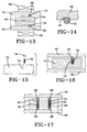
- Figure 13 is a cross-section of a ninth embodiment of the invention.
- Figure 14 shows the groove and spring member of Figure 13 in an enlarged view.
- an armature 64 is movably disposed in a sleeve 60.
- an electric coil 66 causes the armature 64 to move within the sleeve 60.
- the sleeve 60 has at least one groove 62 formed on an interior surface thereof.
- the groove 62 may be formed in the sleeve 60 by, for example, machining.
- a spring member 70 is disposed in the groove 62. The spring member 70 is maintained in place in the sleeve 60 by exerting a radially outwardly directed spring force against the groove 62 in the sleeve 60.
- the inside diameter of the spring member 70 forms a friction fit with the armature 64.
- the dynamic response of the armature 64 may be varied by using spring members 70 with different inside diameters. By changing the inside diameter of the spring member 70, the amount of friction force on the armature 64 changes. The amount of friction may also be changed by adding additional grooves 62 with spring members 70 disposed therein.
- a hole 68 extends axially through the armature 64 so that fluid may flow through the armature from one side to the other.
- the hole 68 may be formed along the longitudinal axis of the armature or may be offset from the longitudinal axis.
- the armature 64 is generally cylindrical in shape, although other shapes of the armature are possible.
- the groove 62 is located on the sleeve 60 where it will not interfere with the magnetic path.
- the groove 62 is concentric with the longitudinal axis of the sleeve.
- the groove 62 extends at least partially around the circumference of the sleeve and may extend completely around the sleeve.
- the spring member 70 may extend partially around the circumference of the sleeve or it may extend completely around the sleeve.
- Figure 15 is an exploded view of a tenth embodiment of the invention.
- Figure 16 is a sectional view of the embodiment of Figure 15.
- the armature 72 includes at least one radial opening 74.
- the radial opening 74 may be formed by, for example, drilling the opening 74 in the armature 72.
- a spring 76 is inserted in the radial opening 74.
- One end of the spring 76 bears against the bottom of the opening 74.
- a bearing member 78 is located on the other end of the spring 76.
- the bearing member 78 may be, for example, a ball bearing.
- the bearing member 78 bears against the sleeve 80 because of the force of the spring member 76.
- the bearing member 78 creates a radially outwardly directed force against the sleeve 80.
- the force created by the bearing member 78 may be varied by changing the spring force of the spring member 76.
- Figure 17 is a sectional view of an eleventh embodiment of the invention.
- the armature 82 includes at least one radial opening 84.
- the radial opening 84 extends completely through the armature 82.
- the radial opening 84 may be formed by, for example, drilling.
- a spring 86 is disposed in the radial opening 84.
- bearing members 88 such as ball bearings.
- the bearing members 88 are in sliding contact with the sleeve 90.
- the spring 86 forces the bearing members 88 radially outward against the sleeve thereby creating friction between the sleeve 90 and the bearing members 88.
- the amount of friction between the sleeve 90 and the bearing members 88 may be varied by changing the spring force of the spring 86.
- the friction force may also be changed by adding additional openings with springs and bearing members.
- Figure 17 shows two radial openings 84 with springs 86 and bearing members 88. Only one opening 84 may be used or more than two may be used, depending on the amount of friction desired.
Landscapes
- Physics & Mathematics (AREA)
- Electromagnetism (AREA)
- Engineering & Computer Science (AREA)
- Power Engineering (AREA)
- General Physics & Mathematics (AREA)
- Automation & Control Theory (AREA)
- Magnetically Actuated Valves (AREA)
- Reciprocating, Oscillating Or Vibrating Motors (AREA)
- Vibration Prevention Devices (AREA)
- Springs (AREA)
- Flow Control (AREA)
Abstract
Description
- The invention relates in general to electromagnetically operated actuators for controlling fluid flow and in particular to varying the dynamic response of such actuators.
- Various components such as servo-valves, pressure regulators and fuel injectors may be used in both open and closed loop dynamic control systems for controlling fluid flow. It may be necessary to change the response characteristic of such components to fine tune the component within the system or to alter the overall system characteristic.
- Electromagnetically operated actuators for controlling fluid flow generally include an armature disposed in a sleeve and actuated by an electric coil. The actuators control the amount of fluid flow at different pressures and are designed to operate within a certain range. Various conditions, such as high pressure and temperature, may push the limits of the actuator's operating range. Conditions such as high pressure and temperature change the operating fluid viscosity dramatically. Such changes in fluid viscosity may force the actuator to become unstable and oscillate. Thus, a need exists for an actuator which remains stable under varying conditions of pressure and temperature.
- The present invention provides an apparatus comprising an armature having at least one groove formed on an exterior surface thereof; a sleeve, the armature being movably disposed in the sleeve; and a spring member disposed in the at least one groove in the armature and in sliding contact with the sleeve wherein the spring member exerts a radially outwardly directed spring force against the sleeve.
- Another aspect of the invention is a method of stabilizing an electromagnetically operated actuator comprising providing an armature having at least one groove formed on an exterior surface thereof; providing a sleeve wherein the armature is movably disposed in the sleeve; and disposing a spring member in the at least one groove in the armature and in sliding contact with the sleeve whereby the spring member exerts a radially outwardly directed spring force against the sleeve.
- Yet another embodiment of the invention is an apparatus comprising a sleeve having at least one groove formed on an interior surface thereof; an armature, the armature being movably disposed in the sleeve; and a spring member disposed in the at least one groove in the sleeve and in sliding contact with the armature wherein the spring member exerts a friction force against the armature.
- Another aspect of the invention is an apparatus comprising an armature having at least one radial opening formed therein; a sleeve, the armature being movably disposed in the sleeve; a spring disposed in the at least one radial opening in the armature; and a bearing member disposed on one end of the spring and in sliding contact with the sleeve wherein the bearing member exerts a radially outwardly directed force against the sleeve.
- Further objects, features and advantages of the invention will become apparent from the following detailed description taken in conjunction with the following drawing.
-
- Figure 1 is a cross-section of a first embodiment of the invention.
- Figure 2 shows the groove and spring member of Figure 1 in an enlarged view.
- Figure 3 is a perspective view of the armature of Figure 1.
- Figure 4 is a perspective view of a second embodiment of the invention.
- Figure 5 is a perspective view of a third embodiment of the invention.
- Figure 6 is a perspective view of a fourth embodiment of the invention.
- Figure 7 is a side view of the embodiment of Figure 6.
- Figure 8 is a perspective view of a fifth embodiment of the invention.
- Figure 9 is a perspective view of a sixth embodiment of the invention.
- Figure 10 is a perspective view of a seventh embodiment of the invention.
- Figure 11 is a perspective view of an eighth embodiment of the invention.
- Figure 12 is a cross-section of the embodiment of Figure 11.
- Figure 13 is a cross-section of a ninth embodiment of the invention.
- Figure 14 shows the groove and spring member of Figure 13 in an enlarged view.
- Figure 15 is an exploded view of a tenth embodiment of the invention.
- Figure 16 is a sectional view of the embodiment of Figure 15.
- Figure 17 is a sectional view of an eleventh embodiment of the invention.
-
- The embodiments of the invention may be used in components such as servo-valves, regulators and injectors for stabilizing system oscillations. An exemplary application is to stabilize fuel system pressure oscillations, although the embodiments may be used in other applications as well.
- The embodiments of the invention include an electromagnetically operated armature. The armature is movably disposed in a sleeve. An electric coil causes the armature to move in the sleeve. At least one groove is formed on an exterior surface of the armature. A spring member is disposed in the groove. The spring member is free to expand and make contact with the sleeve while maintaining contact with the armature. Because it is a spring, the spring member exerts a radially outwardly directed spring force against the sleeve. The spring member, therefore, constantly exerts mechanical friction between the armature and the sleeve. The mechanical friction slows the response of the armature movement and extends the stable operating range of the component in which the armature is disposed.
- Figure 1 is a cross-section of a first embodiment of the invention. Figure 2 shows the groove and spring member of Figure 1 in an enlarged view. Figure 3 is a perspective view of the armature of Figure 1.
- Referring to Figures 1-3, an
armature 20 is movably disposed in asleeve 22. When energized, anelectric coil 24 causes thearmature 20 to move within thesleeve 22. Thearmature 20 has at least onegroove 26 formed on an exterior surface thereof. Aspring member 28 is disposed in thegroove 26 and contacts thesleeve 22. Thespring member 28 exerts a radially outwardly directed spring force against thesleeve 22. Ahole 30 extends axially through thearmature 20 so that fluid may flow through the armature from one side to the other. Thehole 30 may be formed along the longitudinal axis of the armature or may be offset from the longitudinal axis. - Preferably, the
armature 20 is generally cylindrical in shape, although other shapes of the armature are possible. Thegroove 26 may be formed in thearmature 20 by, for example, machining, or thearmature 20 may be cast with thegroove 26 formed during the casting process. Thegroove 26 is located on thearmature 20 where it will not interfere with the magnetic path. - Preferably, the
groove 26 is concentric with the longitudinal axis of the armature. Thegroove 26 extends at least partially around the circumference of the armature and may extend completely around the armature. Likewise, thespring member 28 may extend partially around the circumference of the armature or it may extend completely around the armature. Thespring member 28 also reduces wear on the armature. - The
sleeve 22 andspring member 28 may be made of, for example, metal, plastic or fiber-reinforced plastic. In one embodiment, thespring member 28 is made of piano wire. Whatever the material of construction, thespring member 28 functions as more than a mere seal or bearing surface between thearmature 20 and thesleeve 22. Thespring member 28 functions as an active spring by exerting a radially outwardly directed spring force against thesleeve 22. Thearmature 20 is made of a metal. - The amount of friction between the
spring member 28 and thesleeve 22 may be varied by changing the diameter or the stiffness of thespring member 28. The amount of friction may also be changed by addingadditional grooves 26 withspring members 28 disposed therein. Figure 4 shows anarmature 20 with threegrooves 26 formed therein. - Figure 5 shows an
armature 20 with ahelical groove 32. As in the case of theconcentric grooves 26, thehelical groove 32 receives aspring member 28. - Figure 6 shows an
armature 20 with agroove 34 that is substantially parallel to the longitudinal axis of the armature. Figure 7 is a side view of the armature of Figure 6 showing aspring member 36. Thespring member 36 is substantially horizontal, but is longer than thegroove 34. Because thespring member 36 is longer than thegroove 34, it bows upward to provide a radially outwardly directed spring force against thesleeve 22. - Figure 8 shows an
armature 20 withgroove 26. In this embodiment, thearmature 20 has no through holes. Figure 9 shows anarmature 20 with three throughholes 38. The through holes 38 extend axially through thearmature 20 so that fluid may flow through the armature from one side to the other. The number and placement of the through holes may be varied to suit individual operating conditions. - Figure 10 is a perspective view of another embodiment of the apparatus according to the present invention. The
armature 20 withgroove 26 includes a plunger orvalve member 40. Thevalve member 40 may be formed integrally with thearmature 20 or may be attached to the armature by, for example, threads. Thevalve member 40 may close and open an orifice (not shown) in the particular pressure regulating device within which the armature is disposed. It is also possible that the armature itself, without theadditional valve member 40, may function as a plunger or means for opening and closing an orifice. - Figure 11 is a perspective view of an eighth embodiment of the invention. Figure 12 is a cross-section of the embodiment of Figure 11. The
armature 42 has a generally parallelepiped shape. At least onegroove 44 is formed in thearmature 42. Aspring member 46 is disposed in thegroove 44. In this embodiment, the sleeve wherein thearmature 42 is disposed would also have a generally parallelepiped shape. Other shapes of the armature are also possible, such as a star shape, a triangular shape, a pentagonal shape, etc. - With reference again to Figures 1-3, another embodiment of the invention is a method of stabilizing an electromagnetically operated actuator. The method includes providing an
armature 20 with at least onegroove 26 formed therein. Aspring member 28 is placed in thegroove 26. Thearmature 20 andspring member 28 are disposed in asleeve 22. Thearmature 20 may have no through holes (Figure 8), one through hole (Figure 1) or a plurality of through holes (Figure 9). Because it is a spring, thespring member 28 exerts a radially outwardly directed spring force against thesleeve 22. Thespring member 28 is free to expand and make contact with thesleeve 22 while maintaining contact with thearmature 20. Thespring member 28, therefore, constantly exerts mechanical friction between thearmature 20 and thesleeve 22. The mechanical friction slows the response of the armature movement and extends the stable operating range of the component in which thearmature 20 is disposed. - Figure 13 is a cross-section of a ninth embodiment of the invention. Figure 14 shows the groove and spring member of Figure 13 in an enlarged view.
- Referring to Figures 13 and 14, an
armature 64 is movably disposed in asleeve 60. When energized, anelectric coil 66 causes thearmature 64 to move within thesleeve 60. Thesleeve 60 has at least onegroove 62 formed on an interior surface thereof. Thegroove 62 may be formed in thesleeve 60 by, for example, machining. Aspring member 70 is disposed in thegroove 62. Thespring member 70 is maintained in place in thesleeve 60 by exerting a radially outwardly directed spring force against thegroove 62 in thesleeve 60. - The inside diameter of the
spring member 70 forms a friction fit with thearmature 64. The dynamic response of thearmature 64 may be varied by usingspring members 70 with different inside diameters. By changing the inside diameter of thespring member 70, the amount of friction force on thearmature 64 changes. The amount of friction may also be changed by addingadditional grooves 62 withspring members 70 disposed therein. - A
hole 68 extends axially through thearmature 64 so that fluid may flow through the armature from one side to the other. Thehole 68 may be formed along the longitudinal axis of the armature or may be offset from the longitudinal axis. - Preferably, the
armature 64 is generally cylindrical in shape, although other shapes of the armature are possible. Thegroove 62 is located on thesleeve 60 where it will not interfere with the magnetic path. Preferably, thegroove 62 is concentric with the longitudinal axis of the sleeve. Thegroove 62 extends at least partially around the circumference of the sleeve and may extend completely around the sleeve. Likewise, thespring member 70 may extend partially around the circumference of the sleeve or it may extend completely around the sleeve. - Figure 15 is an exploded view of a tenth embodiment of the invention. Figure 16 is a sectional view of the embodiment of Figure 15. In the embodiment of Figures 15 and 16, the
armature 72 includes at least oneradial opening 74. Theradial opening 74 may be formed by, for example, drilling theopening 74 in thearmature 72. Aspring 76 is inserted in theradial opening 74. One end of thespring 76 bears against the bottom of theopening 74. A bearingmember 78 is located on the other end of thespring 76. The bearingmember 78 may be, for example, a ball bearing. - As shown in Figure 16, the bearing
member 78 bears against thesleeve 80 because of the force of thespring member 76. The bearingmember 78 creates a radially outwardly directed force against thesleeve 80. The force created by the bearingmember 78 may be varied by changing the spring force of thespring member 76. - Figure 17 is a sectional view of an eleventh embodiment of the invention. In Figure 17, the
armature 82 includes at least oneradial opening 84. Theradial opening 84 extends completely through thearmature 82. Theradial opening 84 may be formed by, for example, drilling. Aspring 86 is disposed in theradial opening 84. On each end of thespring 86 are bearingmembers 88, such as ball bearings. The bearingmembers 88 are in sliding contact with thesleeve 90. - The
spring 86 forces the bearingmembers 88 radially outward against the sleeve thereby creating friction between thesleeve 90 and the bearingmembers 88. The amount of friction between thesleeve 90 and the bearingmembers 88 may be varied by changing the spring force of thespring 86. The friction force may also be changed by adding additional openings with springs and bearing members. Figure 17 shows tworadial openings 84 withsprings 86 and bearingmembers 88. Only oneopening 84 may be used or more than two may be used, depending on the amount of friction desired. - While the invention has been described with reference to certain preferred embodiments, numerous changes, alterations and modifications to the described embodiments are possible without departing from the spirit and scope of the invention as defined in the appended claims, and equivalents thereof.
Claims (35)
- An apparatus, comprising:with the sleeve wherein the spring member exerts a radially outwardly directed spring force against the sleeve.an armature having at least one groove formed on an exterior surface thereof;a sleeve, the armature being movably disposed in the sleeve; anda spring member disposed in the at least one groove in the armature and in sliding contact
- The apparatus of claim 1 further comprising an electric coil disposed adjacent the sleeve for moving the armature in the sleeve.
- The apparatus of claim 1 wherein the armature is generally cylindrical in shape.
- The apparatus of claim 3 wherein the at least one groove is concentric with a longitudinal axis of the armature.
- The apparatus of claim 4 wherein the at least one groove extends at least partially around a circumference of the armature and the spring member extends at least partially around the circumference of the armature.
- The apparatus of claim 1 wherein the armature defines at least one hole extending axially through the armature so that fluid may flow through the armature from one side to the other.
- The apparatus of claim 4 wherein the armature has a plurality of grooves defined therein, the grooves being concentric with the longitudinal axis of the armature, the apparatus further comprising a plurality of spring members disposed in the plurality of grooves, respectively.
- The apparatus of claim 3 wherein the groove is formed on the armature in a helical pattern.
- The apparatus of claim 6 wherein the armature defines a plurality of holes extending axially through the armature so that fluid may flow through the armature from one side to the other.
- The apparatus of claim 3 wherein the groove is substantially parallel to a longitudinal axis of the armature.
- The apparatus of claim 1 wherein the armature includes a valve portion extending from one end thereof.
- The apparatus of claim 11 wherein the valve portion is formed integrally with the armature.
- The apparatus of claim 11 wherein the valve portion is threaded into the armature.
- The apparatus of claim 1 wherein the armature has a generally parallelepiped shape.
- The apparatus of claim 1 wherein the sleeve comprises a plastic material.
- The apparatus of claim 1 wherein the sleeve comprises a metal material.
- The apparatus of claim 1 wherein the sleeve comprises a fiber-reinforced plastic material.
- The apparatus of claim 1 wherein the spring member comprises a plastic material.
- The apparatus of claim 1 wherein the spring member comprises a metal material.
- The apparatus of claim 1 wherein the spring member comprises a fiber-reinforced plastic material.
- A method of stabilizing an electromagnetically operated actuator, comprising:providing an armature having at least one groove formed on an exterior surface thereof;providing a sleeve wherein the armature is movably disposed in the sleeve; anddisposing a spring member in the at least one groove in the armature and in sliding contact with the sleeve whereby the spring member exerts a radially outwardly directed spring force against the sleeve.
- An apparatus, comprising:a sleeve having at least one groove formed on an interior surface thereof;an armature, the armature being movably disposed in the sleeve; anda spring member disposed in the at least one groove in the sleeve and in sliding contact with the armature wherein the spring member exerts a friction force against the armature.
- The apparatus of claim 22 further comprising an electric coil disposed adjacent the sleeve for moving the armature in the sleeve.
- The apparatus of claim 22 wherein the armature is generally cylindrical in shape.
- The apparatus of claim 24 wherein the at least one groove is concentric with a longitudinal axis of the sleeve.
- The apparatus of claim 25 wherein the at least one groove extends at least partially around an inner circumference of the sleeve and the spring member extends at least partially around the inner circumference of the sleeve.
- The apparatus of claim 22 wherein the armature defines at least one hole extending axially through the armature so that fluid may flow through the armature from one side to the other.
- An apparatus, comprising:an armature having at least one radial opening formed therein;a sleeve, the armature being movably disposed in the sleeve;a spring disposed in the at least one radial opening in the armature; anda bearing member disposed on one end of the spring and in sliding contact with the sleeve wherein the bearing member exerts a radially outwardly directed force against the sleeve.
- The apparatus of claim 28 wherein the at least one radial opening extends partially through the armature and another end of the spring bears against a bottom of the radial opening in the armature.
- The apparatus of claim 28 wherein the at least one radial opening extends completely through the armature, the apparatus further comprising a second bearing member disposed on another end of the spring and in sliding contact with the sleeve wherein the second bearing member exerts a radially outwardly directed force against the sleeve.
- The apparatus of claim 30 further comprising a plurality of radial openings extending completely through the armature; a plurality of springs disposed in the plurality of radial openings, respectively; a plurality of bearing members, the bearing members disposed on each end of each of the plurality of springs, respectively; wherein the plurality of bearing members are in sliding contact with the sleeve and exert a radially outwardly directed force against the sleeve.
- An apparatus, comprising:an armature;a sleeve, the armature being movably disposed in the sleeve; anda spring member in sliding contact with one of the armature and the sleeve wherein the spring member creates a friction force between the sleeve and the armature.
- The apparatus of claim 32 wherein the armature includes at least one groove formed on an exterior surface thereof; the spring member being disposed in the at least one groove in the armature and in sliding contact with the sleeve wherein the spring member exerts a radially outwardly directed spring force against the sleeve.
- The apparatus of claim 32 wherein the sleeve includes at least one groove formed on an interior surface thereof; the spring member being disposed in the at least one groove in the sleeve and in sliding contact with the armature wherein the spring member exerts a friction force against the armature.
- The apparatus of claim 32 wherein the armature has at least one radial opening formed therein; the spring member comprising a spring disposed in the at least one radial opening in the armature and a bearing member disposed on one end of the spring and in sliding contact with the sleeve wherein the bearing member exerts a radially outwardly directed force against the sleeve.
Applications Claiming Priority (2)
| Application Number | Priority Date | Filing Date | Title |
|---|---|---|---|
| US410584 | 1999-10-01 | ||
| US09/410,584 US6778049B1 (en) | 1999-10-01 | 1999-10-01 | Apparatus and method for changing the dynamic response of an electromagnetically operated actuator |
Publications (2)
| Publication Number | Publication Date |
|---|---|
| EP1089301A1 true EP1089301A1 (en) | 2001-04-04 |
| EP1089301B1 EP1089301B1 (en) | 2008-11-19 |
Family
ID=23625363
Family Applications (1)
| Application Number | Title | Priority Date | Filing Date |
|---|---|---|---|
| EP00117510A Expired - Lifetime EP1089301B1 (en) | 1999-10-01 | 2000-08-14 | Apparatus and method for changing the dynamic response of an electromagnetically operated actuator |
Country Status (5)
| Country | Link |
|---|---|
| US (1) | US6778049B1 (en) |
| EP (1) | EP1089301B1 (en) |
| JP (1) | JP2001146941A (en) |
| KR (1) | KR100755097B1 (en) |
| DE (1) | DE60040825D1 (en) |
Cited By (3)
| Publication number | Priority date | Publication date | Assignee | Title |
|---|---|---|---|---|
| WO2007048705A1 (en) * | 2005-10-24 | 2007-05-03 | Robert Bosch Gmbh | Electromagnetic actuating unit |
| EP3557594A3 (en) * | 2018-04-19 | 2019-11-13 | HUSCO Automotive Holdings LLC | Systems and methods for a solenoid having a dimpled armature tube |
| DE102022131050A1 (en) * | 2022-11-23 | 2024-05-23 | Eto Magnetic Gmbh | Magnetic armature, electromagnetic actuator and method for producing the magnetic armature |
Families Citing this family (18)
| Publication number | Priority date | Publication date | Assignee | Title |
|---|---|---|---|---|
| JP4151335B2 (en) * | 2001-08-07 | 2008-09-17 | 株式会社デンソー | solenoid valve |
| JP2005299683A (en) * | 2001-11-27 | 2005-10-27 | Bosch Corp | Liquid flow control valve and needle anchor |
| JP3820207B2 (en) * | 2002-09-25 | 2006-09-13 | タカノ株式会社 | Flow control valve |
| FR2868497B1 (en) * | 2004-04-02 | 2006-07-07 | Sidel Sas | VALVE COMPRISING A MAGNETIC CONTROL DEVICE |
| JP4697088B2 (en) * | 2006-08-10 | 2011-06-08 | トヨタ自動車株式会社 | solenoid valve |
| US20080266038A1 (en) * | 2007-04-24 | 2008-10-30 | Eaton Corporation | Solenoid assembly |
| JP4465536B2 (en) * | 2007-06-13 | 2010-05-19 | Smc株式会社 | solenoid valve |
| DE102009004803A1 (en) * | 2008-01-17 | 2009-07-23 | Eto Magnetic Gmbh | Electromagnetically actuated valve device |
| KR101077368B1 (en) * | 2009-07-24 | 2011-10-27 | 삼성전기주식회사 | Linear vibration device |
| JP5195740B2 (en) * | 2009-12-25 | 2013-05-15 | トヨタ自動車株式会社 | solenoid valve |
| WO2012087312A1 (en) * | 2010-12-22 | 2012-06-28 | Otis Elevator Company | Frictional damper for reducing elevator car movement |
| WO2013105411A1 (en) * | 2012-01-12 | 2013-07-18 | イーグル工業株式会社 | Solenoid valve |
| JP5906499B2 (en) * | 2012-02-23 | 2016-04-20 | 株式会社デンソー | solenoid valve |
| CN104321576B (en) | 2012-06-21 | 2016-08-24 | 博格华纳公司 | For there being the solenoid motor method of ventilation polluting protection via hydraulic sleeve pipe racks |
| JP6534266B2 (en) * | 2015-02-23 | 2019-06-26 | 株式会社ハーマン | Gas stove |
| US10726982B2 (en) * | 2018-01-30 | 2020-07-28 | Hamilton Sundstrand Corporation | Solenoid including axially aligned guides |
| JP2021125633A (en) * | 2020-02-07 | 2021-08-30 | 日本電産コパル電子株式会社 | Plunger and manufacturing method thereof |
| JP2021145520A (en) * | 2020-03-13 | 2021-09-24 | 株式会社アイシン | Linear actuator |
Citations (7)
| Publication number | Priority date | Publication date | Assignee | Title |
|---|---|---|---|---|
| US2419333A (en) * | 1944-09-20 | 1947-04-22 | Bendix Aviat Corp | Solenoid |
| GB1213925A (en) * | 1968-05-31 | 1970-11-25 | Automatic Switch Co | Solenoid operator having armature provided with guide ring |
| US4044324A (en) * | 1976-04-30 | 1977-08-23 | Ledex, Inc. | Coil compressed plunger cavity components for a wet type solenoid |
| US4131866A (en) * | 1976-05-01 | 1978-12-26 | Expert Industrial Controls Limited | Solenoid devices |
| EP0172591A1 (en) * | 1984-07-12 | 1986-02-26 | WEBER S.r.l. | Improved electroinjector for feeding fuel to an internal combustion engine |
| JPS61116806A (en) * | 1984-11-13 | 1986-06-04 | Canon Inc | solenoid drive mechanism |
| US5345050A (en) * | 1993-06-01 | 1994-09-06 | Caterpillar Inc. | Switch actuating assembly |
Family Cites Families (10)
| Publication number | Priority date | Publication date | Assignee | Title |
|---|---|---|---|---|
| DE172591C (en) | ||||
| NL302113A (en) | 1963-02-26 | |||
| DE2942886C2 (en) | 1979-10-24 | 1983-10-06 | Zahnradfabrik Friedrichshafen Ag, 7990 Friedrichshafen | Electro-hydraulic servo valve |
| US4725039A (en) | 1987-03-17 | 1988-02-16 | Clevite Industries, Inc. | Self-pressure regulating proportional valve |
| US4790345A (en) | 1987-03-17 | 1988-12-13 | Parker-Hannifin Corporation | Proportional valve |
| US4896127A (en) * | 1987-12-21 | 1990-01-23 | Kabushiki Kaisha Nippon Automation | Lagged type solenoid |
| US5005803A (en) | 1988-12-29 | 1991-04-09 | Applied Power Inc. | High response, compact solenoid two-way valve |
| DE4035853C2 (en) | 1990-11-10 | 1994-02-24 | Bosch Gmbh Robert | Pressure control valve |
| US5578978A (en) * | 1992-07-29 | 1996-11-26 | Nartron Corp. | Electro-fluid actuator and system |
| US5663700A (en) * | 1995-08-25 | 1997-09-02 | Trombetta Corporation | Sound dampening solenoid |
-
1999
- 1999-10-01 US US09/410,584 patent/US6778049B1/en not_active Expired - Fee Related
-
2000
- 2000-08-14 EP EP00117510A patent/EP1089301B1/en not_active Expired - Lifetime
- 2000-08-14 DE DE60040825T patent/DE60040825D1/en not_active Expired - Lifetime
- 2000-09-27 JP JP2000294200A patent/JP2001146941A/en not_active Withdrawn
- 2000-09-30 KR KR1020000057579A patent/KR100755097B1/en not_active Expired - Fee Related
Patent Citations (7)
| Publication number | Priority date | Publication date | Assignee | Title |
|---|---|---|---|---|
| US2419333A (en) * | 1944-09-20 | 1947-04-22 | Bendix Aviat Corp | Solenoid |
| GB1213925A (en) * | 1968-05-31 | 1970-11-25 | Automatic Switch Co | Solenoid operator having armature provided with guide ring |
| US4044324A (en) * | 1976-04-30 | 1977-08-23 | Ledex, Inc. | Coil compressed plunger cavity components for a wet type solenoid |
| US4131866A (en) * | 1976-05-01 | 1978-12-26 | Expert Industrial Controls Limited | Solenoid devices |
| EP0172591A1 (en) * | 1984-07-12 | 1986-02-26 | WEBER S.r.l. | Improved electroinjector for feeding fuel to an internal combustion engine |
| JPS61116806A (en) * | 1984-11-13 | 1986-06-04 | Canon Inc | solenoid drive mechanism |
| US5345050A (en) * | 1993-06-01 | 1994-09-06 | Caterpillar Inc. | Switch actuating assembly |
Non-Patent Citations (1)
| Title |
|---|
| PATENT ABSTRACTS OF JAPAN vol. 010, no. 302 (E - 445) 15 October 1986 (1986-10-15) * |
Cited By (3)
| Publication number | Priority date | Publication date | Assignee | Title |
|---|---|---|---|---|
| WO2007048705A1 (en) * | 2005-10-24 | 2007-05-03 | Robert Bosch Gmbh | Electromagnetic actuating unit |
| EP3557594A3 (en) * | 2018-04-19 | 2019-11-13 | HUSCO Automotive Holdings LLC | Systems and methods for a solenoid having a dimpled armature tube |
| DE102022131050A1 (en) * | 2022-11-23 | 2024-05-23 | Eto Magnetic Gmbh | Magnetic armature, electromagnetic actuator and method for producing the magnetic armature |
Also Published As
| Publication number | Publication date |
|---|---|
| KR100755097B1 (en) | 2007-09-04 |
| KR20010050780A (en) | 2001-06-25 |
| EP1089301B1 (en) | 2008-11-19 |
| JP2001146941A (en) | 2001-05-29 |
| DE60040825D1 (en) | 2009-01-02 |
| US6778049B1 (en) | 2004-08-17 |
Similar Documents
| Publication | Publication Date | Title |
|---|---|---|
| US6778049B1 (en) | Apparatus and method for changing the dynamic response of an electromagnetically operated actuator | |
| JP4244805B2 (en) | solenoid valve | |
| KR0177518B1 (en) | Solenoid valve with variable force motor | |
| AU782844B2 (en) | Solenoid operated pressure control valve | |
| US6628186B1 (en) | Solenoid valve | |
| EP1959177B1 (en) | Normally open electromagnetic valve | |
| US6267350B1 (en) | Valve having a mechanism for controlling a nonlinear force | |
| JP2006510845A (en) | Oil spray nozzle for temperature controlled piston cooling | |
| US5284317A (en) | Pressure control valve | |
| JPS61189377A (en) | Pressure regulator | |
| CN101213394A (en) | Device for damping armature stroke in solenoid valve | |
| KR20040014329A (en) | Solenoid operated pressure control valve | |
| US20040211463A1 (en) | Proportional solenoid valve and control method therefor | |
| JP3666693B2 (en) | Electromagnetic fuel injection device | |
| KR100950171B1 (en) | Electromagnetic valve, in particular for automatic gearboxes | |
| US7398795B2 (en) | Excess flow valve | |
| US6675751B1 (en) | Two-mass bi-directional hydraulic damper | |
| EP1394368B1 (en) | A Hydraulic Damper for an Electromechanical Valve | |
| CN116792506A (en) | Electric valve and method for assembling electric valve | |
| JP4199698B2 (en) | solenoid valve | |
| JP3637402B2 (en) | Electromagnetic device | |
| JP4151335B2 (en) | solenoid valve | |
| EP3604871A1 (en) | Solenoid valve | |
| JP2001165344A (en) | Solenoid valve | |
| WO2024210067A1 (en) | Solenoid |
Legal Events
| Date | Code | Title | Description |
|---|---|---|---|
| PUAI | Public reference made under article 153(3) epc to a published international application that has entered the european phase |
Free format text: ORIGINAL CODE: 0009012 |
|
| AK | Designated contracting states |
Kind code of ref document: A1 Designated state(s): DE FR GB IT |
|
| AX | Request for extension of the european patent |
Free format text: AL;LT;LV;MK;RO;SI |
|
| 17P | Request for examination filed |
Effective date: 20010917 |
|
| AKX | Designation fees paid |
Free format text: DE FR GB IT |
|
| RAP1 | Party data changed (applicant data changed or rights of an application transferred) |
Owner name: SIEMENS VDO AUTOMOTIVE CORPORATION |
|
| 17Q | First examination report despatched |
Effective date: 20031124 |
|
| GRAP | Despatch of communication of intention to grant a patent |
Free format text: ORIGINAL CODE: EPIDOSNIGR1 |
|
| GRAS | Grant fee paid |
Free format text: ORIGINAL CODE: EPIDOSNIGR3 |
|
| GRAA | (expected) grant |
Free format text: ORIGINAL CODE: 0009210 |
|
| AK | Designated contracting states |
Kind code of ref document: B1 Designated state(s): DE FR GB IT |
|
| REG | Reference to a national code |
Ref country code: GB Ref legal event code: FG4D |
|
| REF | Corresponds to: |
Ref document number: 60040825 Country of ref document: DE Date of ref document: 20090102 Kind code of ref document: P |
|
| RAP2 | Party data changed (patent owner data changed or rights of a patent transferred) |
Owner name: CONTINENTAL AUTOMOTIVE SYSTEMS US, INC. |
|
| PLBE | No opposition filed within time limit |
Free format text: ORIGINAL CODE: 0009261 |
|
| STAA | Information on the status of an ep patent application or granted ep patent |
Free format text: STATUS: NO OPPOSITION FILED WITHIN TIME LIMIT |
|
| 26N | No opposition filed |
Effective date: 20090820 |
|
| GBPC | Gb: european patent ceased through non-payment of renewal fee |
Effective date: 20090814 |
|
| REG | Reference to a national code |
Ref country code: FR Ref legal event code: ST Effective date: 20100430 |
|
| PG25 | Lapsed in a contracting state [announced via postgrant information from national office to epo] |
Ref country code: FR Free format text: LAPSE BECAUSE OF NON-PAYMENT OF DUE FEES Effective date: 20090831 |
|
| PG25 | Lapsed in a contracting state [announced via postgrant information from national office to epo] |
Ref country code: GB Free format text: LAPSE BECAUSE OF NON-PAYMENT OF DUE FEES Effective date: 20090814 |
|
| PG25 | Lapsed in a contracting state [announced via postgrant information from national office to epo] |
Ref country code: IT Free format text: LAPSE BECAUSE OF FAILURE TO SUBMIT A TRANSLATION OF THE DESCRIPTION OR TO PAY THE FEE WITHIN THE PRESCRIBED TIME-LIMIT Effective date: 20081119 |
|
| REG | Reference to a national code |
Ref country code: DE Ref legal event code: R081 Ref document number: 60040825 Country of ref document: DE Owner name: CONTINENTAL AUTOMOTIVE SYSTEMS, INC. ( N. D. G, US Free format text: FORMER OWNER: SIEMENS VDO AUTOMOTIVE CORP., AUBURN HILLS, US Effective date: 20110728 Ref country code: DE Ref legal event code: R082 Ref document number: 60040825 Country of ref document: DE Representative=s name: FISCHER, MICHAEL, DR., DE Effective date: 20110728 |
|
| PGFP | Annual fee paid to national office [announced via postgrant information from national office to epo] |
Ref country code: DE Payment date: 20120831 Year of fee payment: 13 |
|
| REG | Reference to a national code |
Ref country code: DE Ref legal event code: R119 Ref document number: 60040825 Country of ref document: DE |
|
| REG | Reference to a national code |
Ref country code: DE Ref legal event code: R082 Ref document number: 60040825 Country of ref document: DE Representative=s name: FISCHER, MICHAEL, DR., DE |
|
| REG | Reference to a national code |
Ref country code: DE Ref legal event code: R082 Ref document number: 60040825 Country of ref document: DE Representative=s name: FISCHER, MICHAEL, DR., DE Effective date: 20140317 Ref country code: DE Ref legal event code: R081 Ref document number: 60040825 Country of ref document: DE Owner name: CONTINENTAL AUTOMOTIVE SYSTEMS, INC. ( N. D. G, US Free format text: FORMER OWNER: CONTINENTAL AUTOMOTIVE SYSTEMS US, INC. (N. D. GESETZEN DES STAATES DELAWARE), AUBURN HILLS, US Effective date: 20140317 |
|
| PG25 | Lapsed in a contracting state [announced via postgrant information from national office to epo] |
Ref country code: DE Free format text: LAPSE BECAUSE OF NON-PAYMENT OF DUE FEES Effective date: 20140301 |
|
| REG | Reference to a national code |
Ref country code: DE Ref legal event code: R119 Ref document number: 60040825 Country of ref document: DE Effective date: 20140301 |