EP1089252B1 - Stable stand for a pedal-driven musical instrument - Google Patents
Stable stand for a pedal-driven musical instrument Download PDFInfo
- Publication number
- EP1089252B1 EP1089252B1 EP00121428A EP00121428A EP1089252B1 EP 1089252 B1 EP1089252 B1 EP 1089252B1 EP 00121428 A EP00121428 A EP 00121428A EP 00121428 A EP00121428 A EP 00121428A EP 1089252 B1 EP1089252 B1 EP 1089252B1
- Authority
- EP
- European Patent Office
- Prior art keywords
- stand
- musical instrument
- pedestal
- set forth
- connector
- Prior art date
- Legal status (The legal status is an assumption and is not a legal conclusion. Google has not performed a legal analysis and makes no representation as to the accuracy of the status listed.)
- Expired - Lifetime
Links
Images
Classifications
-
- G—PHYSICS
- G10—MUSICAL INSTRUMENTS; ACOUSTICS
- G10D—STRINGED MUSICAL INSTRUMENTS; WIND MUSICAL INSTRUMENTS; ACCORDIONS OR CONCERTINAS; PERCUSSION MUSICAL INSTRUMENTS; AEOLIAN HARPS; SINGING-FLAME MUSICAL INSTRUMENTS; MUSICAL INSTRUMENTS NOT OTHERWISE PROVIDED FOR
- G10D13/00—Percussion musical instruments; Details or accessories therefor
- G10D13/01—General design of percussion musical instruments
- G10D13/06—Castanets, cymbals, triangles, tambourines without drumheads or other single-toned percussion musical instruments
- G10D13/063—Cymbals
- G10D13/065—Hi-hats
Definitions
- This invention relates to a stand for a musical instrument and, more particularly, to a stand for a percussion instrument such as, for example, high-hat cymbals.
- the high-hat cymbals form a drum set together with a bass drum, a snare drum, a set of tom toms, a floor tom and a side cymbal. Only one drummer sits on a chair among the percussion instruments, and performs music through those percussion instruments. Accordingly, the percussion instruments are to be arranged on a floor within the reach of drummer's hands. Although the drummer strikes the snare drum, the tom toms, the floor tom and the side cymbal with sticks, the bass drum and the high-hat cymbals are usually actuated by the drummer's foot.
- Foot pedals are placed on the floor near the chair, and are linked with a bass drum beater and a rod, respectively.
- the rod is connected to the upper high-hat cymbal, and the upper high-hat cymbal is opposed to the lower high-hat cymbal.
- the bass drum beater strikes the skin of the bass drum, and the rod clashes the upper high-hat cymbal against the lower high-hat cymbal.
- the space within the reach of drummer's hands is so narrow that the drummer is to arrange the percussion instruments closely. For this reason, the percussion instrument is expected to occupy the floor as narrow as possible.
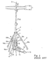
- Figures 1 and 2 show a typical example of the stand for the high-hat cymbals.
- the stand for the high-hat cymbals is hereinbelow referred to as "high-hat stand".
- the prior art high-hat stand is put on a floor FL, and keeps the high-hat cymbals 1 spaced therefrom.
- One of the high-hat cymbals 1 is stationary, and is labeled with reference 1A.
- the other of the high-hat cymbals 1 is movable, and is labeled with 1B.
- the movable cymbal 1B is spaced from the stationary cymbal 1A, and is clashed against the stationary cymbal 1A for generating indefinite pitched sound.
- the prior art high hat stand comprises a telescopic guide 2, an extension rod 9, a pedal mechanism 3 and a foldable tripod 4.
- a spring unit 6, plural pipes 7/ 8, a suitable coupling and a thumbscrew constitute the telescopic guide 2, and the extension rod 9 is slidable inside the telescopic guide 2.
- the extension rod 9 is inserted into the telescopic guide 2, and projects from the upper end of the pipe 8 and the lower end of the spring unit 6.
- the stationary cymbal 1A is fixed to the upper end of the pipe 8, and the movable cymbal 1B is fixed to the extension rod 9.
- the pedal mechanism 3 is connected to the lower end of the extension rod 9.
- the spring unit 6 includes a cylindrical case 6a, a return spring 10 and a retainer ring 6c.
- the cylindrical case 6a is fixed to the lower end of the pipe 7, and the retainer ring 6c is fixed to the extension rod 9.
- the return spring 10 is accommodated in the cylindrical case 6a, and is connected at one end thereof to the retainer ring 6c and at the other end thereof to the bottom portion of the cylindrical case 6a.
- the return spring 10 upwardly urges the extension rod 9 at all times.
- the movable cymbal 1B is spaced from the stationary cymbal 1A under the condition that any force is not exerted on the pedal mechanism 3.
- the movable cymbal 1B is clashed against the stationary cymbal 1A.
- the coupling is attached to the pipe 7, and prohibits the pipe 8 from coming out of the other pipe 7.
- the pipe 8 is stretchable from and retractable into the pipe 7, and the thumbscrew fixes the relative position between the pipes 7 and 8.
- the foldable tripod 4 includes three legs 16a/ 16b/ 16c, retainer rings 17/19 and three foldable stays 18a/ 18b/ 18c.
- the three legs 16a/ 16b/ 16c are connected at upper ends thereof to the retainer ring 17, and the retainer ring 17 is fixed to the pipe 7.
- the other retainer ring 19 is fixed to the cylindrical case 6a, and is closer to the floor FL than the retainer ring 17.
- the three legs 16a/ 16b/ 16c are angularly spaced at 120 degrees from one another.
- the foldable stays 18a/ 18b/ 18c are connected at the inner ends thereof to the retainer ring 19 and at the outer ends thereof to the legs 16a/ 16b/ 16c. When the stays 18a/18b/18c are stretched, the legs 16a/16b/16c brace the telescopic guide 2 on the floor FL, and keeps the guide 2 and, accordingly, the high-hat cymbals 1 upright.
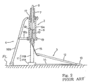
- the pedal mechanism 3 includes a pedestal 11, a foot pedal 12, a heel 13, a connecting rod 14 and a flexible connector 15.
- the pedestal 11 has an L-letter shape, and is formed of light metal such as aluminum alloy.
- the pedestal 11 is broken down into a base plate 11A and a frame 11B.
- the base plate 11A is placed on the floor FL, and the cylindrical case 6a is fixed to the frame 11B.
- the pedestal 11 makes the floor FL receive the weight of the telescopic guide 2, and the foldable tripod 4 keeps the telescopic guide 2 upright on the floor FL.
- the heel 13 is connected through the connecting rod 14 to the base plate 11A.
- the connecting rod 14 spaces the heel 13 from the base plate 11A by a predetermined distance.
- the connecting rod 14 is only expected to space the heel 13 from the base plate 11A, and the diameter is 6 millimeters.
- the foot board 12 is hinged at one end thereof to the heel 13 and at the other end thereof to the extension rod 9 through the flexible connector 15.
- the flexible connector 15 is, by way of example, formed of leather, and changes the rotation of the foot pedal 12 around the heel 13 to the straight motion of the extension rod 9.
- the narrower the occupation area the closer the percussion instruments. If the legs 16a/ 16b/ 16c are long and widely spread, the high-hat stand occupies wide area, and other percussion instruments are sparsely arranged around the drummer. The drummer may find it hard to beat the farthest percussion instrument. On the other hand, if the legs 16a/ 16b/16c are short and narrowed, the high-hat stand is unstable, and feel the arrangement on the floor overcrowded. While a drummer is performing the drum set, the drummer is liable to hit his leg against the leg 16a/ 16b/ 16c, and bring down the high-hat stand.
- leg 16a/ 16b/ 16c of the prior art high-hat stand is evenly spaced from the other legs 16b/ 16c/ 16a at 120 degrees
- another prior art high- hat stand has a trapezoid, the legs of which are unevenly spaced.
- the legs are assumed to be corresponding to the legs 16a/ 16b/ 16c.
- the leg 16b is located at the back of the foot pedal, and each of the other two legs 16a/16c is spaced from the leg 16b at 105 degrees. This means that the leg 16a is spaced from the leg 16c at 150 degrees.
- the arrangement of legs makes the prior art high-hat stand more unstable than the evenly arranged legs 16a/ 16b/ 16c.
- the perpendicular line is shorter than that of the legs 16a/ 16c, and the prior art high- hat stand is much liable to fall down sideways.
- the prior art high-hat stand has only two legs.
- the prior art high-hat stand has a supporting board projecting from the pedestal of the pedal mechanism toward the drummer.
- the contact spots of the two legs and the supporting board are located at the three vertexes of a virtual triangle on the floor, and set the telescopic guide upright.
- the Japanese Patent Publication of Unexamined Application teaches another supporting board projectable from and retractable into the pedestal of the pedal mechanism. When a drummer draws out the slide board from the pedestal, the slide board and the contact spots of the two legs are located at the three vertexes of the virtual triangle on the floor, and also set the telescopic guide upright.
- Still another prior art high-hat stand is disclosed in U.S. Patent No. 510,5706.
- the prior art high-hat stand also has two legs, and the heel is connected through a rigid connecting rod and a base plate to the pedestal.
- the contact spots of the two legs and the base plate are located at the three vertexes of a virtual triangle, and set the telescopic guide upright.
- the prior art high-hat stand is also stable on a flat surface, and creates a space around drummer's foot.
- the prior art high-hat stand requires additional parts, and the drummer is to attach the base plate to the pedestal by using a tuning key or a wrench before setting the telescopic guide upright. The drummer feels the setting work and the disassembling work onerous.
- the base plate has fairly wide bottom surface.
- the base plate is an eyesore, and makes the prior art high-hat stand ill-shaped.
- JP-A-11/11/219169 was used as a basis for the preamble of claim 1 and discloses a structure of a bearing holding part for a musical instrument.
- a bearing holding structure for the performance operation part of a musical instrument like a hi-hat stand a slotted part is provided for a holding hole used for holding a bearing having an internally coupled shaft member.
- a bolt is passed from one free arm part forming the slotted part to the other free arm part and then tightened to hold the bearing.
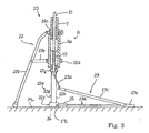
- a high-hat stand embodying the present invention largely comprises a telescopic guide 20, an extension rod 21, a supporting structure 22 and a pedal mechanism 23.
- words “front” and “rear” are representative of relative relation between two positions. The word “front” modifies a position closer to a drummer siting on a chair for performing music, and word “rear” modifies a position farther from the drummer than the front position.
- the telescopic guide 20 is similar in structure to the telescopic guide 2 incorporated in the prior art high-hat stand shown in figure 1, and the components of the telescopic guide 20 are labeled with the references designating corresponding components of the telescopic guide 2 without detailed description.
- the extension rod 21 is inserted into the inner space of the telescopic guide 20, and projects from the both ends of the telescopic guide 20.
- high-hat cymbals are connected to the upper end of the telescopic guide 20 and the upper end of the extension rod 21, and are opposed to each other as similar to the high-hat cymbals 1.
- the supporting structure 22 includes a pair of legs 22a, a pair of stays 22b, retainer rings 22c/ 22d, a pedestal 22e, a heel 23a and a connector 23b.
- the heel 23a and the connector 23b are shared between the supporting structure 22 and the pedal mechanism 23 as will be hereinbelow described in detail.
- the pair of legs 22a is stretchable, and downwardly projects from the telescopic guide 20.
- the telescopic guide 20 is put on the pedestal 22e, and is fixed thereto.
- the heel 23a is connected to the pedestal 22e by means of the connector 23b.
- the pedestal 22e and the heel 23a are placed on the floor FL.
- the connector 23b is spaced from the floor 23b.
- the pair of legs 22a, the pedestal 22e and the heel 23a are held in contact with the floor FL.
- the retainer rings 22c and 22d are fixed to the pile 7 and the cylindrical case 6a, respectively.
- the legs 22a are hinged at the upper end thereof to the retainer ring 22c, and the stays 22b are hinged at the inner ends thereof to the other retainer ring 22d.
- elongated holes are formed in intermediate portions of the legs 22a. Pins are respectively attached to the outer ends of the stays 22b, and are slidably received in the elongated holes.
- the stays 22b are turnable around the retainer ring 22d. When a drummer changes the stays 22b to a position close to the pedestal 22e, the legs 22a are pulled toward the telescopic guide 20, and the high-hat stand occupies narrow space.
- the high-hat stand is ready for storage.
- the stays 22b turn around the retainer ring 22d over 90 degrees, and keep the legs 22a spaced from the pedestal 22e.
- the contact spots between the legs 22a and the floor FL and the contact spot between the heel 23a and the floor occupy the three vertexes of a virtual triangle.
- the pedestal 22e supports most of the weight of the telescopic guide 20, the extension rod 21 and the high-hat cymbals, the legs 22a and the heel 23a stably set the telescopic guide 20 upright on the floor FL.
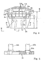
- the pedestal 22e includes a base plate 22f and a frame 22g.
- the frame 22g has two posts 22h and a lateral bar 22j.
- the two posts 22h are connected to both end portions of the lateral bar 22j.
- the telescopic guide 20 is fixed to the lateral bar 22j, and the posts 22h are embedded into the base plate 22f.
- the base plate 22f is broken down into a supporting block 24 and an extension block 25.
- the supporting block 24 and the extension block 25 are formed in a monolithic structure.
- the supporting block 24 has a leaf-like configuration, and ribs 24a reinforce the supporting block 24.
- a pair of vertical holes 24b and a pair of lateral holes 24c are formed in the supporting block 24.
- the vertical holes 24b are located in both side portions of the supporting block 24, and are open to the upper surface of the supporting block 24.
- the two posts 22h are snugly inserted into the vertical holes 24b.
- the supporting block 24 receives most of the total weight of the telescopic guide 20, the extension rod 21 and the high-hat cymbals.
- the lateral holes 24c are formed in the lugs, respectively, and are open to the gap.
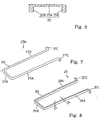
- the extension block 25 has an upper flat portion 25A and a pair of side walls 25B.
- the side walls 25B downwardly project from both side portions of the upper flat plate 25A (see figure 6), and form a gap therebetween.
- the rear portions of the side walls 25B are formed with recesses corresponding to the lugs, and the lugs are snugly received in the recesses, respectively.
- the gap between the lugs is overlapped with the gap between the side walls 25B, and the gap is open to the front surface of the extension block 25.
- the connector 23b is formed from a round bar 28 of metal or alloy.
- the round bar 28 is bent four times, and the connector 23b has a U-letter shape as shown in figure 7.
- the connector 23b has a pair of longitudinal portions 27A, a lateral portion 27B and a pair of lugs 27C.
- the longitudinal portions 27A backward project from both ends of the lateral portion 27B, and the lugs 27C sideward project from the rear ends of the longitudinal portions 27A.
- the lateral portion 27B is connected to the heel 23a by means of a bracket and bolts.
- a drummer takes the longitudinal portions 27A in his grasp so as to elastically deform the longitudinal portions 27A inwardly.
- the drummer inserts the longitudinal portions 27A into the gap between the side walls 25B until the lugs 27C reach the lateral holes 24c.
- the drummer aligns the lugs 27C with the lateral holes 24c, and release the longitudinal portions 27A.
- the longitudinal portions 27A elastically expand, and the lugs 27C are inserted into the lateral holes 24c, respectively.
- the connector 23b is assembled with the supporting block 24 without any tool.
- only the connector 23b is used for the interconnection between the base plate 24 and the heel 23a, and the supporting structure 22 is simpler than that of the prior art high-hat stands.
- the pedal mechanism 23 includes the heel 23a, the connector 23b, a foot pedal 23c and a flexible connector 23d.
- the foot pedal 23c is hinged to the heel 23a at one end thereof, and the flexible connector 23d is connected between the lower end of the extension rod 21 and the other end of the foot pedal 23c.
- the flexible connector 23d is formed of leather.
- the pedal mechanism 23 is similar to that of the prior art high-hat stand.
- the connector 23b cooperates with the heel 23a so as to prevent the telescopic guide 20 from the violent fall.
- a drummer sets the high-hat stand upright on the floor FL, and attaches the high-hat cymbals 1 separately to the telescopic guide 20 and the extension rod 21.
- the total weight of the telescopic guide 20, the extension rod 21 and the high-hat cymbals 1 are assumed to be exerted on the center of gravity, and the center of gravity is found on a center line of the extension rod 21 or the extension line thereof.
- the extension block 25 frontward projects from the supporting block 24, and is integral therewith.
- the front end of the extension block 25 is farther from the posts 22h than the base plate 11A of the prior art high-hat stand.
- the distance L between the front end and the posts 22h is 70 to 100 millimeters.
- the distance L1 between the front end of the supporting block 24 and the front end of the extension block 25 is of the order of 50 millimeters, and the distance L2 between the lateral holes 24c and the front end of the supporting block 24 is of the order of 16 millimeters.
- the base plate 11A of the prior art high-hat stand is equivalent to the supporting block 24, and the distance from the posts 22h and the front end of the base plate 11A is prolonged by L1, i.e., about 50 millimeters long.
- the extension rod 21 and the high-hat cymbals 1 make the high-hat stand unstable.
- the distance L is to be longer than the offset.
- the present inventor investigated the motion of the high-hat stand used for standard high-hat cymbals, and experimentally determined the maximum value of the offset. Although the distance between the posts and the front end is less than the maximum offset in the prior art high-hat stand, the distance L is greater than the maximum offset, and the extension block 25 enhances the stability of the high-hat stand.
- the round bar 28 is 8 millimeters in diameter, and the geometrical moment of inertia is 200.96 mm 4 .
- the connector 23b is more than three times larger in geometrical moment of inertia than that of the prior art high-hat stand. Accordingly, the connector 23b is larger in modulus of section than the connector 14. For this reason, the connector 23b keeps the longitudinal portions 27A straight against the maximum bending moment larger than that exerted on the connector 14.
- the modulus of section permits the player to elastically deform it.
- the flexural strength of the connector 23b is to be large enough to keep the longitudinal portions 27A straight against the bending moment exerted thereon during the performance.
- the maximum bending moment exerted during performances was hot constant among drummers, the present inventor experimentally determined the bending moment exerted during the performances and the flexural strength of the connector 23b to be required.
- the modulus of section of the round bar used for the prior art connector 14 makes the maximum bending stress larger than the critical value
- the round bar 28 has the flexural strength much larger than the maximum bending stress due to the bending moment experimentally determined.
- the connector 23b prevents the high-hat stand and the high-hat cymbals from a violent fall, and is conducive to the stability of the high-hat stand according to the present invention.
- Equation 1 X1/ X2 ⁇ 0.3
- X1 is the distance between the center lines of the posts 22h and the front end of the extension block 25
- X2 is the distance between the center lines of the posts 22h and the front end of the heel 13.
- the connector 23b is formed from a single bar, and the heel 23a is connected to the pedestal 22e by means of the simple connector 23b. This results in a simple structure and good appearance. Moreover, the production cost is reduced.
- the connector 23b is elastically engaged with the base plate 22f, and a drummer can assemble the pedal mechanism 23 with the pedestal 22e without any tool. This results in the mechanism being easy to use.
- the extension block 25 frontward projects from the supporting block 24, and prevents the high-hat cymbals 1 attached to the telescopic guide/ extension rod 20/ 21 from a violent fall toward the drummer.
- the connector 23b has a large bending strength larger than the maximum bending moment exerted thereon during usual performance, and permits the heel 23a to prevent the high-hat cymbals 1 attached to the telescopic guide/ extension 20/21 from a violent fall.
- the high-hat stand implementing the first embodiment is simple and easy to use without sacrifice of the stability.
- a connector 29 incorporated in another high-hat stand embodying the present invention is formed from a rectangular bar 30 of metal or alloy.
- the high-hat stand implementing the second embodiment is similar in structure to the first embodiment except the connector 29. For this reason, description is focused on the connector 29, and no further description is incorporated hereinbelow for the sake of simplicity.
- the rectangular bar 30 is four times bent, and the connector 29 has a generally U-letter shape.
- Longitudinal portions 29A are rearward projecting from both ends of a lateral portion 29B, and lugs 29C are sideward projecting from the longitudinal portions 29A.
- the lugs 29C are inserted into the lateral holes 24c of the supporting block 24, and the heel 23a is connected to the supporting block 24 by means of the connector 29.
- the connector 29 serves as similar to the connector 23b of the first embodiment.
- the connector 29 is different in cross section from the connector 23b.
- the connector 29 has a rectangular cross section.
- the width is 4 millimeters, and the height is 6 millimeters.
- the geometric moment of inertia, i.e., I bh3 / 12 where b is width and h is height, is the diameter, is 72.
- the connector 29 is larger in geometric moment of inertia than the connector 14 of the prior art high-hat cymbal.
- the connector 29 is larger in modulus of section than the connector 14. For this reason, the connector 23b keeps the longitudinal portions 29A straight against the maximum bending moment experimentally determined.
- the high-hat stand implementing the second embodiment achieves all the advantages of the first embodiment.
- the extension block 25, the connector 23b/ 29 and the heel as a whole constitute a safety device against overturning.
- the telescopic guide 20 and the extension rod 21 form in combination a driving mechanism.
- the present invention is applicable to another stand for a musical instrument equipped with a pedal mechanism.
- a high-hat stand may be equipped with the spring unit attached to the outer surface of the telescopic guide.
- Yet another embodiment may have the connector directly connected to the supporting block.
- the safety device against the overturning is implemented by the combination of the connector and the heel.
- the lateral holes may be replaced with gaps formed between pairs of projections so that the lugs are snugly received in the gaps.
- the round bar and the rectangular bar may have the values of the geometric moment of inertia larger than those of the above-described embodiments.
Description
Claims (9)
- A stand for a musical instrument comprisinga driving mechanism (20/ 21) connected to said musical instrument (1) and actuated for generating sound,a pedal mechanism (23) having a pedal plate (23c) connected to said driving mechanism and manipulated by a player for actuating said driving mechanism and a heel (23a) placed on a surface (FL) and providing an axis of rotation to said pedal plate, anda supporting structure (22) connected to said driving mechanism (20/21) and said pedal mechanism (23) for setting said driving mechanism (20/21) stably on said surface (FL), and including a pedestal (22e) placed on said surface (FL) and receiving the total weight of said driving mechanism (20/21) and said musical instrument (1), anda safety device (25/ 23b; 25/29) against overturning connected between said pedestal (22e) and said heel (23a)
characterized in that
said safety device includes a connector (23b; 29) formed from a single bar (28; 30) having a modulus of section and a U-letter shape and being elastically connected to said pedestal (22c) at bifurcated end portions thereof so as to keep the elasticity thereof against a maximum bending moment exerted thereon during a performance, thereby preventing said musical instrument from a violent fall during said performance. - The stand for a musical instrument as set forth in claim 1, in which said bifurcated end portion is formed with lugs (27C; 29C) sidewardly projecting, and said pedestal (22e) is formed with holes (24c) where said lugs are snugly received.
- The stand for a musical instrument as set forth in claim 1, in which the generally U-letter shaped bar (28) has a circular cross section.
- The stand for a musical instrument as set forth in claim 3, in which said circular cross section has a diameter greater than 6 millimeters.
- The stand for a musical instrument as set forth in claim 1, in which the generally U-letter shaped bar (30) has a rectangular cross section.
- The stand for a musical instrument as set forth in claim 5, in which said rectangular cross section has a geometric moment of inertia larger than 63.58 mm4.
- The stand for a musical instrument as set forth in claim 1, in which said safety device against overturning further includes an extension block (25) projecting from said pedestal (22e) toward said heel (23a) and having a leading end spaced from a virtual line vertically passing through said pedestal (22e) and carrying a center of gravity for said total weight by a distance longer than an offset of said center of gravity when said maximum bending moment is exerted.
- The stand for a musical instrument as set forth in claim 7, in which said extension block (25) is integral with a base plate (24) forming said pedestal (22e) together with a vertical portion (22h) upwardly projecting from said base plate (24).
- The stand for a musical instrument as set forth in claim 7, in which said extension block (25) has an upper flat plate (25A) and side walls (25B) downwardly projecting from both side portions of said upper flat plate (25A) and held in contact with said floor (FL) so that said side walls (25B) spaces said upper flat plate (25A) from said surface (FL).
Applications Claiming Priority (2)
| Application Number | Priority Date | Filing Date | Title |
|---|---|---|---|
| JP27964799 | 1999-09-30 | ||
| JP27964799A JP3528705B2 (en) | 1999-09-30 | 1999-09-30 | Musical instrument stand |
Publications (2)
| Publication Number | Publication Date |
|---|---|
| EP1089252A1 EP1089252A1 (en) | 2001-04-04 |
| EP1089252B1 true EP1089252B1 (en) | 2005-11-23 |
Family
ID=17613906
Family Applications (1)
| Application Number | Title | Priority Date | Filing Date |
|---|---|---|---|
| EP00121428A Expired - Lifetime EP1089252B1 (en) | 1999-09-30 | 2000-09-29 | Stable stand for a pedal-driven musical instrument |
Country Status (4)
| Country | Link |
|---|---|
| US (1) | US6326534B1 (en) |
| EP (1) | EP1089252B1 (en) |
| JP (1) | JP3528705B2 (en) |
| DE (1) | DE60024194T2 (en) |
Families Citing this family (1)
| Publication number | Priority date | Publication date | Assignee | Title |
|---|---|---|---|---|
| US10854176B1 (en) * | 2019-12-27 | 2020-12-01 | Joshua Lupton | High hat stand assembly |
Family Cites Families (13)
| Publication number | Priority date | Publication date | Assignee | Title |
|---|---|---|---|---|
| US3464305A (en) | 1967-05-02 | 1969-09-02 | Remo Meazzi | Stand for supporting and moving a pair of cymbal plates |
| US3988957A (en) * | 1975-09-09 | 1976-11-02 | The Raymond Lee Organization, Inc. | Drum pedal assembly |
| US4111095A (en) * | 1977-11-02 | 1978-09-05 | Simons Steven R | Percussion instrument mounting apparatus |
| US4381690A (en) * | 1981-03-02 | 1983-05-03 | Baldwin Piano & Organ Company | Cymbal stand |
| US4488471A (en) * | 1983-05-19 | 1984-12-18 | Youakim Phillip M | High-hat cymbal stand and method of setting up the same |
| US5105706A (en) | 1991-01-14 | 1992-04-21 | Lombardi Donald G | Music stand pedal frame and dual leg support |
| JP2544766Y2 (en) | 1991-02-26 | 1997-08-20 | 星野楽器株式会社 | Hi-hat stand |
| JP2546113Y2 (en) | 1993-02-04 | 1997-08-27 | ヤマハ株式会社 | Hi-hat stand |
| JP2738318B2 (en) * | 1994-12-06 | 1998-04-08 | ヤマハ株式会社 | Drum foot pedal |
| US5574237A (en) * | 1995-09-27 | 1996-11-12 | Pearl Musical Instrument Co. | Bass drum pedal assembly with moveable heel plate |
| JP3131397B2 (en) * | 1997-02-18 | 2001-01-31 | 星野楽器株式会社 | Hi-hat stand |
| JPH11219169A (en) | 1998-01-29 | 1999-08-10 | Hoshino Gakki Kk | Structure of bearing holding part for musical instrument |
| JP3062388U (en) | 1999-03-24 | 1999-10-08 | 廖 村淇 | Hi-hat cymbal foot pedal |
-
1999
- 1999-09-30 JP JP27964799A patent/JP3528705B2/en not_active Expired - Lifetime
-
2000
- 2000-09-28 US US09/670,928 patent/US6326534B1/en not_active Expired - Lifetime
- 2000-09-29 EP EP00121428A patent/EP1089252B1/en not_active Expired - Lifetime
- 2000-09-29 DE DE60024194T patent/DE60024194T2/en not_active Expired - Lifetime
Also Published As
| Publication number | Publication date |
|---|---|
| US6326534B1 (en) | 2001-12-04 |
| EP1089252A1 (en) | 2001-04-04 |
| JP3528705B2 (en) | 2004-05-24 |
| JP2001100736A (en) | 2001-04-13 |
| DE60024194D1 (en) | 2005-12-29 |
| DE60024194T2 (en) | 2006-07-20 |
Similar Documents
| Publication | Publication Date | Title |
|---|---|---|
| US6211448B1 (en) | Drum set | |
| US9082375B2 (en) | Percussion instrument and stand for the same | |
| JP3131397B2 (en) | Hi-hat stand | |
| US6002076A (en) | Double-mallet heel-toe drum pedal system with hinged mallets | |
| US4111095A (en) | Percussion instrument mounting apparatus | |
| US7435888B2 (en) | Electronic drum pedal | |
| US7378584B2 (en) | Drum | |
| US6903257B2 (en) | Bass drum pedal with eccentricity-adjustable cam system | |
| EP3580749B1 (en) | Compact drum kit | |
| US6528714B1 (en) | Hi-hat cymbal stand | |
| US7576275B2 (en) | Drum lift | |
| JP6589548B2 (en) | Percussion pedal device | |
| JP3514174B2 (en) | Musical instrument stand | |
| US6255574B1 (en) | Single and double beat base pedal | |
| EP1089252B1 (en) | Stable stand for a pedal-driven musical instrument | |
| US3742806A (en) | Apparatus for use in playing pecussion instruments | |
| US20060042451A1 (en) | Alternating cymbals | |
| JP2562460Y2 (en) | Drum pedal beater structure | |
| EP0903724B1 (en) | Stand for musical instrument less obstructive to player | |
| JP2011039506A (en) | Pedal for drum | |
| JP2007256626A (en) | Foot pedal and percussion instrument | |
| JP3475918B2 (en) | Drum set connector | |
| JP2806300B2 (en) | Drum foot pedal | |
| JPH0725840Y2 (en) | Cowbell equipment | |
| JP2019184939A (en) | Support device for kick pad |
Legal Events
| Date | Code | Title | Description |
|---|---|---|---|
| PUAI | Public reference made under article 153(3) epc to a published international application that has entered the european phase |
Free format text: ORIGINAL CODE: 0009012 |
|
| AK | Designated contracting states |
Kind code of ref document: A1 Designated state(s): DE GB |
|
| AX | Request for extension of the european patent |
Free format text: AL;LT;LV;MK;RO;SI |
|
| 17P | Request for examination filed |
Effective date: 20011004 |
|
| AKX | Designation fees paid |
Free format text: DE GB |
|
| 17Q | First examination report despatched |
Effective date: 20040720 |
|
| GRAP | Despatch of communication of intention to grant a patent |
Free format text: ORIGINAL CODE: EPIDOSNIGR1 |
|
| GRAS | Grant fee paid |
Free format text: ORIGINAL CODE: EPIDOSNIGR3 |
|
| GRAA | (expected) grant |
Free format text: ORIGINAL CODE: 0009210 |
|
| AK | Designated contracting states |
Kind code of ref document: B1 Designated state(s): DE GB |
|
| REG | Reference to a national code |
Ref country code: GB Ref legal event code: FG4D |
|
| REF | Corresponds to: |
Ref document number: 60024194 Country of ref document: DE Date of ref document: 20051229 Kind code of ref document: P |
|
| PLBE | No opposition filed within time limit |
Free format text: ORIGINAL CODE: 0009261 |
|
| STAA | Information on the status of an ep patent application or granted ep patent |
Free format text: STATUS: NO OPPOSITION FILED WITHIN TIME LIMIT |
|
| 26N | No opposition filed |
Effective date: 20060824 |
|
| PGFP | Annual fee paid to national office [announced via postgrant information from national office to epo] |
Ref country code: DE Payment date: 20190918 Year of fee payment: 20 |
|
| PGFP | Annual fee paid to national office [announced via postgrant information from national office to epo] |
Ref country code: GB Payment date: 20190920 Year of fee payment: 20 |
|
| REG | Reference to a national code |
Ref country code: DE Ref legal event code: R071 Ref document number: 60024194 Country of ref document: DE |
|
| REG | Reference to a national code |
Ref country code: GB Ref legal event code: PE20 Expiry date: 20200928 |
|
| PG25 | Lapsed in a contracting state [announced via postgrant information from national office to epo] |
Ref country code: GB Free format text: LAPSE BECAUSE OF EXPIRATION OF PROTECTION Effective date: 20200928 |